Getinge 30 User manual

Service Manual
Getinge Ultrasonic
Ultrasonic Cleaning Units
english

Content
2
SM_Getinge-Ultrasonic_07.2013_EN
© Getinge Group
Content
General............................................................................. 4
1.1 How to use the Service Manual................................ 4
1.2 Contents of the Service Manual............................... 4
1.3 Demands on the service staff................................... 5
1.4 Testing equipment, tools and measuring instruments5
2Important safety warnings ......................................... 6
3Organizational details................................................. 7
3.1 Warranty.................................................................. 7
3.2 Warranty period....................................................... 7
3.3 Ordering of spare parts............................................ 7
3.4 How to find out the year of manufacturing................ 8
4Product description..................................................... 9
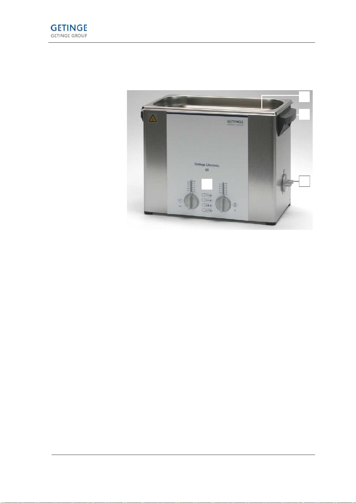
4.1 Unit features –front view ......................................... 9
4.2 Description operating elements...............................10
4.3 Technical details.....................................................11
4.4 Operating and display functions..............................12
4.5 Circuit diagram Getinge Ultrasonic..........................15
5Trouble shooting / Table of malfunctions.................. 16
5.1 Table of malfunctions..............................................17
6How to open the unit ................................................ 24
6.1 Getinge Ultrasonic 30, 40, 70, 80............................24
6.2 Getinge Ultrasonic 60, 100 –300............................25
6.3 How to close the unit / How to mount the bottom
plate........................................................................25
7How to remove / replace the turning knobs.............. 26
7.1 How to remove the turning knobs............................26
7.2 How to mount the turning knobs..............................27
8How to replace the PCB control ............................... 28
8.1 Electric connections................................................28
8.2 How to remove the PCB control..............................29
8.3 How to mount the PCB control................................30
9How to replace the PCB interference filter................ 31
9.1 Getinge Ultrasonic 30 - 40 ......................................31
9.1.1 How to remove the PCB interference filter...........32
9.1.2 How to mount the PCB interference filter.............33
9.2 Getinge Ultrasonic 60 - 100 ....................................35
9.2.1 How to remove the PCB interference filtern.........36
9.2.2 How to mount the PCB interference filter.............37

Content
© Getinge Group
SM_Getinge-Ultrasonic_07.2013_EN
3
9.3 Getinge Ultrasonic 120 - 300 ..................................39
9.3.1 How to remove the PCB interference filter...........39
9.3.2 How to mount the PCB interference filter.............40
10 How to replace the potentiometer for the cleaning
period / for temperature......................................... 42
11 How to replace the front panel............................... 43
12 How to replace the PCB support ........................... 44
13 How to replace the heating.................................... 45
14 Replacement of piezoceramics ............................. 47
15 Replacement of transducer tank............................ 52
16 Replacement of drain duct..................................... 55
16.1 How to replace the turning knob drain duct.............55
16.2 How to replace the ball valve ..................................56
17 Replace the handle................................................ 58
18 Putting into operation / Trial run ............................ 59
18.1 How to fill cleaning liquid.........................................59
18.2 Cleaning media.......................................................60
18.3 Heating of the cleaning liquid..................................60
18.4 Check ultrasound....................................................60
19 Putting out of operation and disposal .................... 62
20 Contact address .................................................... 62
21 Conclusion............................................................. 62

General
4
SM_Getinge-Ultrasonic_07.2013_EN
© Getinge Group
General
Carefully read the Service Manual before you carry out any
repair works, in particular the Important safety warnings,
section 2.
We assume that the person carrying out the described repair
works is sufficiently educated in the field of safety and
electronics skills. The basic safety instructions are not explicitly
given for each repair work.
We reserve the right to carry out technical modifications on the
units due to advanced development.
Reprints, translations and copying of any kind, even of parts of
the document, are subject to prior written authorization by the
editor.
The copy right remains with the editor.
1.1 How to use the Service Manual
For trouble shooting we recommend to use the table of possible
malfunctions (section 5).
Further useful information on the operation of the unit can be
found in the description of the unit (section 4).
Please observe the important safety warnings (section 2), and
the information on initial operation (section 17).
In case of any further queries Getinge will be glad to assist. For
our technical support and contact address please see the last
page.
1.2 Contents of the Service Manual
Carefully read and observe before you carry out any repair
works
Description of operating elements and unit feature
Instructions on the intended use and operation of the present
unit
Table of malfunctions, possible causes and remedies for the
different unit types (no guarantee on completeness)
Easy-to-follow instructions on the replacement of faulty
components; individual unit types are listed separately where
necessary
Instructions on initial operation / putting into operation, cleaning
media, heating of the cleaning liquid, etc.
Appendix A contains circuit diagrams for each unit type showing
the relevant data
Appendix B contains the spare parts lists, divided into separate
lists for each unit type. The lists indicate the standard spare
parts. Should you require any further components, please
contact the manufacturer.
Safety warnings
Product description
Operation
Trouble shooting
Repair
Putting into
operation / Trial run
Circuit diagrams
Spare parts lists

General
© Getinge Group
SM_Getinge-Ultrasonic_07.2013_EN
5
1.3 Demands on the service staff
The present Service Manual is intended for authorized service
points and specialized service staff.
Legitimate users of the Service Manual are persons who do not
require to be specifically instructed on the risks caused by
electric equipment.
Special knowledge on electric unit and safety-relevant
knowledge are prerequisite for carrying out any repair works on
ultrasonic cleaning units.
1.4 Testing equipment, tools and measuring instruments
All testing and measuring tools and instruments must be
connected to a grounded socket only.
Apart from the standard electromechanical tools the follwoing
measuring and testing equipment is required for carrying out
the measuring and repair works described in the present
Service Manual:
For electric measuring inside the unit, e.g. resistance and
throughline measuring.
Adjusting range up to approx. 100 Nm. For tests and repair
works which require the opening of the transducer system. After
opening, the transducer system must be screwed with the
correct torque (see section Transducer system). The wrong
torque can cause malfunctions and a breakdown of the unit.
For checking the power consumption of the ultrasonic generator
and the heating.
Power 4 Ampere or more. For the separation of the unit from
the mains and for the safe and controlled upward-adjustment of
the mains voltage.
Certain components on the electronic PCB can be damaged
through electrostatic charges. Therefore, it is absolutely
necessary for the service staff to discharge statically before
they touch the electronic PCB and to remain earthed when
handling the component.
The following items are required for arranging an ESD
protected workplace:
ESD work pad; ESD floor surface; Tools
ESD earthing connection from the wrist of the person to the
work pad; ESD shoes
ESD protective bag; ESD boxes / cartons
Multimeter
Torque wrench
Wattmeter
Adjustable
interrupting
transformer
ESD protective
measures
Room
Staff
Packing

Important safety warnings
6
SM_Getinge-Ultrasonic_07.2013_EN
© Getinge Group
2 Important safety warnings
Carefully read and observe before inspection and
reoperation of the unit!
The present ultrasonic cleaning unit has been designed for the
treatment of items and liquids only.
Repair and maintenance works which require the unit to be
opened and connected must be carried out by authorized
specialized staff only.
Check the unit and the mains cable for transport damages. In
case of any visible damage do not operate the unit!
Place the unit on a dry and solid surface; ensure that the
workplace is sufficiently ventilated. Keep workplace, unit
housing and operating elements dry. Protect the unit from
entering humidity!
Separate the unit from the mains before you open it.
In order to prevent damages from persons and/or from the unit
all connected electric measuring instruments and the ultrasonic
unit must be connected via an interrupting transformer.
Parts of the ultrasonic generator and the transducer system
carry high-frequency AC voltage during operation.
Due to piezoelectric effects there can be high voltages
produced by exchanging the transducer disks. Earth these
voltages before you touch the transducer disks.
100 –120 V or 220 –240 V
1 phase / 1 N / 1 PE shockproof grounded socket
Fill the cleaning tank with a sufficient quantity of a suitable
cleaning liquid before switch-on. Do not use flammable liquids
directly in the cleaning tank: risk of fire and explosion!
For safety reasons, the present unit must be connected to a
correctly grounded socket only. The technical details indicated
on the nameplate must correspond with the available mains
connection details, in particular those of the mains voltage and
the current connected value.
In order to guarantee compliance with the valid safety
regulations and the CE conformity faulty parts must be replaced
by original spare parts only.
The manufacturer cannot be held liable for damages on
persons, on the unit or on the workshop equipment caused by
improper use or wrong repair.
Intended use
Authorized
specialized staff
Check for damage
Placement
Prevention of
electrical accidents
Mains connection
Cleaning liquid
Mains connection
Original spare parts
Exclusion of liability

Organizational details
© Getinge Group
SM_Getinge-Ultrasonic_07.2013_EN
7
3 Organizational details
3.1 Warranty
The warranty covers all claims based on material and
manufacturing faults. Excluded from the warranty are:
Transport damages; these must be reported to the
forwarding agent immediately upon detection.
Damages caused by improper use of the unit:
e.g. damages on the transducer tank caused by wrong
cleaning media, cleaning items placed directly on the tank
floor, dry running of the unit, etc.
Damages caused by humidity which has entered the unit
from outside.
Unauthorized repair works on the unit.
Improper use and/or operation against the Operating
Instructions.
Wear and tear; example: the transducer tank is a wear part
with regard to the cavitational erosion around the sound-
giving surfaces.
3.2 Warranty period
The limitation period of warranty claims is 2 years (from the
date of purchase). If no proof of purchase can be produced,
Getinge can find out the date of manufacturing by means of the
serial number (nameplate).
Getinge grant a limitation period of 2 years on all exchange
parts and on any repair works carried out.
Please ensure that all documentation concerning the service
works carried out are safely stored.
3.3 Ordering of spare parts
Getinge guarantee the availability of spare parts according to
the valid regulations over a period of 10 years after production
and sale of a unit have stopped. Standard spare parts will be
available for older units.
For your spare parts order we need to know the following data:
Type of unit
Voltage (115 V or 230 V)
Serial number (nameplate)
New units
Repair

Organizational details
8
SM_Getinge-Ultrasonic_07.2013_EN
© Getinge Group
3.4 How to find out the year of manufacturing
The year of manufacturing of a unit can be taken from the serial
number indicated on the nameplate.
The serial number is required e.g. for revision purposes, for
spare parts orders and for the determination of the warranty
period.
The first figure (A) –starting from the left –represents the
decade.
The second and third figures (B) –starting from the right –
represent the month.
The first figure (A) –starting from the right –represents the
year.
Example:
S/N 10 4 8 0 0 043
April 2013
A
B
C

Product description
© Getinge Group
SM_Getinge-Ultrasonic_07.2013_EN
9
4 Product description
4.1 Unit features –front view
Illustration 4.1.1 Front view Getinge Ultrasonic 30
Maximum filling level indication (indicates the recommended
maximum filling level. This level should not be exceeded even
with immersed cleaning items.
Plastic handles (on Getinge Ultrasonic 30 and larger) for the
safe transportation of the unit, even when heated.
Turning knob for draining the transducer tank (on Getinge
Ultrasonic 30 and larger)
Vertical position: drain open
Horizontal position: drain shut.
Operating elements for the control of the unit functions
description see sections 4.2.
A
B
C
D
B
A
D
C

Product description
10
SM_Getinge-Ultrasonic_07.2013_EN
© Getinge Group
4.2 Description operating elements
Illustration 4.2.1 View operating elements, unit with heating
Turning knob cleaning period * Available options: short-term
operation: 1; 2; 3; 4; 5; 10; 15; 20; 25; 30 min (with automatic
switch-off).
Permanent operation ∞. Switch-off by hand.
For reasons of safety the unit is automatically switched off after
12 h permanent operation.
LED display cleaning period for set period and remaining
period indication.
Turning knob temperature * on units with heating.
Temperature range adjustable in 5 °C steps between 30 and
80 °C.
LED display temperature on units with heating.
Display of set temperature and actual temperature of the liquid.
Key sweep function for the optimum sound field distribution in
the cleaning bath. Sweep LED.
Kea degas function (by hand and Auto Degas –see Table
4.7)Degas function for the efficient degassing of the cleaning
liquid and for special laboratory cleaning jobs. Degas LED.
Key ultrasonic operation and temperature-controlled
ultrasonic operation. Ultrasound LED
Key on/off for switching the unit on and off.
On/off LED
* setting of the required value: turn clockwise
reset: turn anti-clockwise
A
B
C
D
E
F
G
H
A
F
G
E
B
D
C
H

Product description
© Getinge Group
SM_Getinge-Ultrasonic_07.2013_EN
11
4.3 Technical details
Mains voltage unit
variants
(Vac)
Ultrasoun
d
frequency
(kHz)
Power
consumpti
on total
(W)
Ultrasonic
power RMS
(W)
Ultrasonic
maximum
peak power*
(W)
Heating
power
(W)
30
100-120 | 220-240
37
280
80
320
200
40
100-120 | 220-240
37
340
140
560
200
60
100-120 | 220-240
37
550
150
600
400
70
100-120 | 220-240
37
750
150
600
600
80
100-120 | 220-240
37
750
150
600
600
90
100-120 | 220-240
37
550
150
600
400
100
100-120 | 220-240
37
550
150
600
400
120
100-120 | 220-240
37
1000
200
800
800
130
100-120 | 220-240
37
1100
300
1200
800
150
100-120 | 220-240
37
300
300
1200
-
180
100-120 | 220-240
37
1000
200
800
800
300
100-120 | 220-240
37
1500
300
1200
1200
*: Impulse sound; 30 –300: Double half-wave sound. The form of signal has been adapted to the geometry of
the transducer tank. Depending on the form of signal the peak of the ultrasonic power is 4 or 8-fold.

Product description
12
SM_Getinge-Ultrasonic_07.2013_EN
© Getinge Group
4.4 Operating and display functions
For your information: Specific displays of the unit types Getinge
Ultrasonic 30 - 300 are listed separately.
Action
To do
Result
Display
Switch on the unit
press on/off key
unit is ready for
operation
on/off LED is on
Switch off the unit
press on/off key
unit is off
all displays dark
Start the ultrasound
- now -
set the required
period at the turning
knob for cleaning
period
press ►■key
(ultrasound)
ultrasound operates
LED ultrasound is on
set period is indicated
by LED
LED indicating
remaining period
flashes (only in timer
operating mode)
Start the ultrasound
- temperature-controlled*;
with revolution of cleaning
bath –
* if set temperature >
actual temperature;
only on units with heating
set required period
set temperature at
turning knob
keep key ►■
pressed (> 2 sec.)
heating operates
ultrasound starts
automatically when
the set temperature is
reached
set period of
ultrasonic activity runs
down
LED ultrasound
flashes
LED set period
flashes
LED ultrasound is
turned on when set
temperature is
reached
LED set period is
turned on
LED remaining period
flashes
Stop ultrasound by hand
set required period to
„0“
or
press ►■key
ultrasound is turned
off
LED ultrasound is
turned off
LED set period is
turned on

Product description
© Getinge Group
SM_Getinge-Ultrasonic_07.2013_EN
13
Action
To do
Result
Display
Switch on heating*
*only on units with heating
set required
temperature
heating operates
LED set temperature
is turned on
LED actual
temperature flashes
and moves towards
set temperature
When actual = set
temperature only the
LED set temperature
is on
When actual > set
temperature the LED
actual temperature
starts flashing again
Switch off heating by
hand
set temperature to „0“
position
heating switches off
LED actual
temperature flashes
Switch on sweep function*
* Sweep and degas
cannot be operated at the
same time
set the required
period
press ►■key
press Sweep key
ultrasound operates
in sweep mode
LED ultrasound is
turned on
LED sweep is turned
on
LED set temperature
is turned on
LED remaining period
flashes
Switch on degas function*
* Sweep and Degas
cannot be operated at the
same time
set the required
period
press ►■key
press Degas key
ultrasound operates
in degas mode
LED degas is turned
on
LED ultrasound is
turned on
Getinge Ultrasonic
30 - 300: LED set
period is turned on
LED remaining period
flashes

Product description
14
SM_Getinge-Ultrasonic_07.2013_EN
© Getinge Group
Action
To do
Result
Display
Switch off sweep-function
press Sweep key
sweep function is
switched off
ultrasound continues
operation in standard
mode
LED sweep is turned
off
LED ultrasound is
turned on
LED set period is
turned on
LED remaining period
flashes
Switch off degas function
press Degas key
Degas function is off
Ultrasound continues
operating in standard
mode
LED degas is turned
off
LED ultrasound is on
LED set temperature
is on
LED remaining period
flashes
Switch on Auto-Degas
function*
* Sweep and Degas
cannot be operated at the
same time
press ►■key
keep Degas key
pressed (> 2 sec.)
Ultrasound operates
in Auto-Degas mode
for 10 minutes and
switches off
subsequently
LED degas flashes
LED ultrasound is
turned on

Product description
© Getinge Group
SM_Getinge-Ultrasonic_07.2013_EN
15
4.5 Circuit diagram Getinge Ultrasonic

Trouble shooting / Table of malfunctions
16
SM_Getinge-Ultrasonic_07.2013_EN
© Getinge Group
5 Trouble shooting / Table of malfunctions
Find out if the malfunction is caused by a fault on the unit or by
improper use. Examples for malfunctions due to improper use:
The cleaning result is not satisfactory:
The cleaning medium, the cleaning temperature or the
duration of the cleaning cycle are not suitable for the
cleaning task.
The cleaning result can also be impaired by a wrong or
insufficient filling level and/or very dirty cleaning liquid.
The unit does not heat up correctly:
For an efficient heating up of the cleaning liquid switch on
the ultrasound (see section 4.5. Start the ultrasound –
temperature-controlled*;with revolution of the cleaning bath)
and use a cover.
Check and find out if the fault is in the heating or in the
ultrasonic system.
Check housing and bottom plate of the unit for any visible
damage and check the tank for leaks before you connect the
unit to an interrupting transformer.
Then connect the unit to an adjustable interrupting transformer
for a functional check. You can easily and safely check the unit
for a short circuit by slowly adjusting the mains voltage upwards
and observing the current consumption. At the same time you
can find out which functions of the unit have broken down.
Various malfunctions are indicated by a flashing LED display:
Getinge Ultrasonic 30 - 300: LED display cleaning period
flashes fast („running light“) / LED display in the ultrasound key
flashes fast:
There is a fault on the PCB control, on the connection between
ultrasound >> transducer system or on the transducer system.
Getinge Ultrasonic 30 - 300: LED display heating temperature
flashes fast („running light“) / LED display in the ultrasound key
flashes fast:
There is a fault in the temperature measuring, e.g. interrupted
connection to temperature gauge or a faulty gauge.
Improper use
Faulty unit
LED display
malfunction
Ultrasound
malfunction
Temperature
malfunction

Trouble shooting / Table of malfunctions
© Getinge Group
SM_Getinge-Ultrasonic_07.2013_EN
17
5.1 Table of malfunctions
Malfunction
Cause
Measuring
Result >> Action
No unit function:
No ultrasound
and
no heating (on
units with
heating)
and
all LED displays
dark
Broken/interrupted
mains cable
or
mains supply
socket damaged
or
interruption on pcb
interference filter
or
interruption in
connecting cable
PCB interference
filter >> PCB
control
or
fault on PCB
control
1. measure mains supply voltage
Check if there is mains
voltage at input
interference filter.
How to proceed:
Open the unit
(see section 6 )
Mesure the voltage at the
fuses on the input side
(see illustration 5.1.A)
or check the fuse for
throughline with ohmmeter
No mains moltage at
input side of fuses:
Check the mains cable for
damage and check electric
throughline
Check mains supply socket
for damage and check
electric throughline
Action:
Replace faulty parts by
original spare parts
Voltage at input side of
fuses: (see illustration
5.1.A)
Continue with 2.
2. Check fuses on interference filter
Measure mains voltage on
output side of fuses or
check throughline of fuses
Fuses are OK
Continue with 3.
Fuses are faulty:
Check fuse data (see
spare parts list)
Fuses are faulty and fuse
data are wrong:
Mount fuses with correct
data
Fuses are faulty, fuse
data are correct:
There is a short circuit in
the unit (e.g. heating
element; PCB control,
PCB; interference filter).
Check for transport
damage or humidity inside
the unit.
Continue with 5.

Trouble shooting / Table of malfunctions
18
SM_Getinge-Ultrasonic_07.2013_EN
© Getinge Group
...
No unit function:
No ultrasound
and
no heating (on
units with
heating)
and
all LED displays
dark
Measuring
Result >> Action
3. Check PCB interference filter for interruption
Measure mains voltage
at output of PCB
interference filter:
How to proceed:
Check if there is mains
voltage between the
contacts of the voltage
supply to the heating
element and of the voltage
supply PCB interference
filter. (See illustration
5.1.B.)
or check fuse through-line
with ohmmeter
4. Check mains voltage
of PCB control
No mains voltage at
output of PCB
interference filter:
There is an electrical fault
on the PCB interference
filter.
Action:
Replace PCB interference
filter by original spare part.
How to proceed:
see section 9
There is mains voltage at
the output of the PCB
interference filter:
There is probably a fault on
the PCB control.
Possible the connecting
cable between PCB
interference filter and PCB
control is interrupted.
4. Check voltage supply from control PCB
Check connecting cable
between PCB
interference filter and
PCB control for
interruption
How to proceed:
Pull off the plug of the
connection wire (from
interference filter) and
measure at the contacts 1
(white) + 2 (black).
No mains voltage:
The connecting cable
between PCB interference
filter and PCB control has
been interrupted.
Action:
Replace complete cable
No mains voltage at
input PCB control:
PCB control is faulty.
Action:
Replace PCB control (see
section 9)

Trouble shooting / Table of malfunctions
© Getinge Group
SM_Getinge-Ultrasonic_07.2013_EN
19
...
No unit function:
No ultrasound
and
no heating (on
units with
heating)
and
all LED displays
dark
Measuring
Result >> Action
5. Check unit for short circuit (of fuses on PCB
interference filter faulty, fuse data correct)
Probably there is a short
circuit in the unit (PTC
heating element; PCB
control; PCB interference
filter).
How to proceed:
The individual components
must be checked
separately.
6. check filter PCB for short circuit
How to proceed:
Check for scorchings /
traces of water in the
mains socket
Mount new fuses into PCB
interference filter
Pull off the connecting
cable between PCB
interference elimination
and PCB control,
preferably at the PCB
control.
Separate the supply wire
from the PTC heating
element at the respective
plug contact on the PCB
interference filter.
Connect the unit to the
mains for testing
purposes.
Fuses on PCB
interference filter are
blown again:
Short circuit on PCB
interference filter. Replace
interference filter (see
section 9)
Fuses on PCB
interference filter are not
blown:
PCB interference filter is
OK.
Short circuit is probably in
PTC heating element or
PCB control
Continue with 7.
7. Check heating element for short circuit
Separate the heating
element from the mains
How to proceed:
Separate the supply wire
from the heating element
at the respective plug
contacts on the
interference filter.
Connect the unit to the
mains.
Fuses on the
interference filter are not
blown:
Short circuit in the heating
element. Replace the
heating element (see
section 13)
Fuses on the
interference filter are
blown:
Heating element is OK.
Probably short circuit in
PCB control
Continue with 8

Trouble shooting / Table of malfunctions
20
SM_Getinge-Ultrasonic_07.2013_EN
© Getinge Group
...
No unit function:
No ultrasound
and
no heating (on
units with
heating)
and
all LED displays
dark
8. Check PCB control for short circuit
Separate PCB control
from the mains
How to proceed:
Pull off the connecting
cable between PCB
interference filter and PCB
control, preferably at the
plug of the PCB control.
Connect the unit to the
mains.
Fuses on the PCB
interference filter are not
blown:
Short circuit on PCB
control.
Replace PCB control (see
section 8).
Fuses on PCB
interference filter are
blown again:
Check unit for:
loose or wrongly plugged
cables, loose unit
components, entered
humidity.
Malfunction
Cause
Measuring
Result >> Action
No ultrasound
and
Display LEDs for
ultrasound are
flashing in
malfunction
indicating mode
Faulty PCB control
Check voltage supply of PCB control
How to proceed:
Pull off the plug of the
connecting cable (from
PCB interference filter)
and measure at contacts 1
(white) + 2 (black).
No mains voltage:
Action:
Replace complete cable
Check PCB interference
filter and connecting cable
for faults (continue with 3.
and 4)
Mains voltage at input of
PCB control:
PCB control is faulty.
Action:
Replace PCB control (see
section 8)
This manual suits for next models
11
Table of contents
Other Getinge Ultrasonic Jewelry Cleaner manuals
Popular Ultrasonic Jewelry Cleaner manuals by other brands

Nikro
Nikro WC20110 instruction manual

Jon-Don
Jon-Don Prospector PE5003 operating instructions

Batavia
Batavia MAXXPACK BT-NXF001 operating instructions

Ryobi
Ryobi RY18PCA Original instructions

General Pipe Cleaners
General Pipe Cleaners Kinetic Water Ram operating instructions

Chapman
Chapman PC120 Original instructions