GRS Positioning Vise User manual

PAGE 1 of 2 LIT-003-168
Positioning Vise For Engravers and Jewelers Using a Microscope
INSTRUCTIONS • #003-541
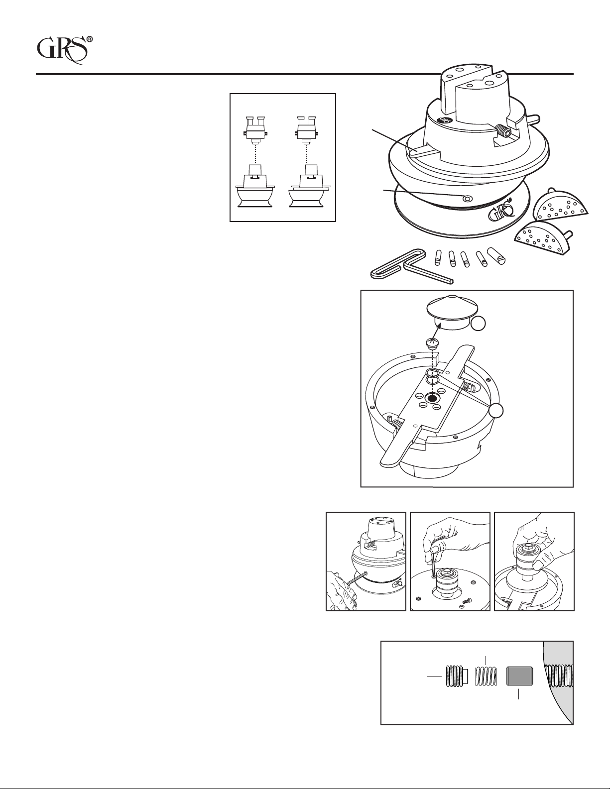
How To Position
Make sure the vise head is in the center
of the vise base. Place the vise directly in
the center under the microscope (FIG. 1).
Pressing the “Release Lever” will free
the vise head so that it may be moved or
slide in any desired direction. Release the
lever and the vise head locks in place and
will rotate from that desired point (FIG. 2).
Users will quickly learn to position the
vise while looking through the scope.
Maintenance
Based on usage, open jaws fully and clean any dirt and metal pieces
from the threads. After cleaning, apply a small amount of light oil to
the threads.
Wear Repair
Parts that may wear and eventually need replacing are the “Lock
Button” (FIG. 3.A) located at the center of the position release lever and
the “Jaw Thread Pins” (FIG. 8) located in each jaw.
Loss of Locking Tension
If the vise head does not stay in locked position, tighten the tension.
Loosen the Rotational Drag Screw located on the side of the ball
(FIG. 4). Lift the upper portion of the vise out of the base. Turn the vise
head upside down and rest it on its top.
Remove the four hex head bolts (FIG. 5) from the mounting plate and
lift the plate off. Set the bearing / post assembly (FIG. 6) to the side. The
lock button (FIG. 3.A) is now visible in the center of the lever handle.
Remove the lock button with a small screwdriver by prying it up.
The button should have a 3/32" at in the center of the crown. If the
button is damaged or excessively worn, we recommend replacing
it. If it looks in good shape, you can add tension by placing shim
washers (FIG. 3.B) under the button. This will raise it to create more
locking tension.
Reassemble the vise by placing the bearing / post in the center
of the vise head as shown in Figure 6. Set the mounting plate
over the bearing/post and align the bolts.
Pull the release lever open to move the vise head. Hold it in
that position and then tighten the four bolts down. Hold the
lever open when tightening the bolts or damage to the lock
button will occur.
Place the vise head into the base and tighten the ball swivel
tension screw (FIG. 4).
FIG. 1 FIG. 2
Lock Button 3/32"
Flat center peak
Shim
Washers
FIG. 4 FIG. 5 FIG. 6
Rotational
Drag
Screw
Position
Release Lever
A
B
FIG. 3
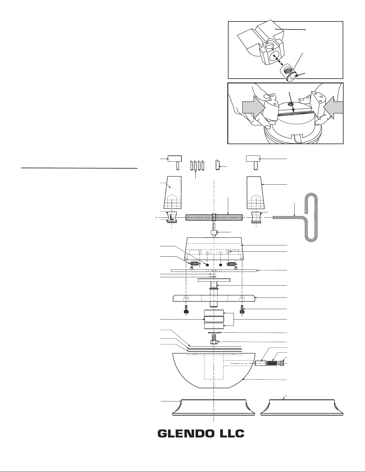
Rotational Lock Replacement
The LOCK or DRAG PIN is subject to wear and may need replacement
after extended use. Simply remove the ball swivel tension screw with the
hex wrench. The Spring and Lock Pin should follow (FIG. 7). If not, turn
the ball until they fall out. Replace the Lock Pin (#003-046), Spring, and
Tension Screw.
Thread Pin Replacement Kit • #003-627
Includes Jaw Screw, Left and Right Thread Pins, O-Rings, and Tube
of Synthetic Grease.
Lock Pin
#003-046
Tension
Screw
Spring
FIG. 7

PAGE 2 of 2 LIT-003-168
003-064
003-007
003-009
003-065
003-008
002-450 003-142
003-151
003-206
003-207
003-540
003-148
002-067
022-171
022-149
022-150
003-143 002-212
002-214
002-112
003-144
003-020
003-067
003-141
002-127
003-507 003-508
003-015
003-016
002-091
002-174
003-538
003-146
033-021
033-020
GRS Positioning Vise
Complete Assembly #003-541
PART # DESCRIPTION
002-067 #10-32 x 1/2" SHCS
002-091 Wrench 1/4" T Handle Allen
002-112 5/16"-18 x 3/4" HHB
002-127 O-Ring, 0.625 x 0.75 x .062
002-174 Roll Pin, 1/8" x 3/4"
002-212 Bearing, 5/8" x 1/2"
002-214 Washer, 0.312 x 0.859 x 0.125
002-450 Bearing 5/16" Steel Ball
003-007 Jaw Screw
003-008 Jaw, Left Hand
003-009 Jaw, Right Hand
003-015 Pin, 1/4"
003-016 Pin, 3/8"
003-020 Spring, Block Drag
003-064 Thread Pin, Left Hand
003-065 Thread Pin, Right Hand
003-067 1/2”-13 x 1/2” SSS FLT PT HF
003-141 Base-Positioning Vise
003-142 Vise Crown S.S.
003-143 Spacer, Drag Pin
003-144 Drag Pin
003-146 Yoke
003-148 Mounting Plate
003-151 Spring
003-206 Shim Washer
003-207 Lock Button
003-507 Pin Plate Assembly (2 Pin)
003-508 Pin Plate Assembly (1 Pin)
003-538 Post
003-540 Handle Assembly
022-149 Bearing
022-150 Race-.031 THK
022-171 Thrust Washer-.078 THK
033-020 Large Block Base Ring Plastic
033-021 Large Block Base Ring Rubber
900 Overlander Road • Emporia, KS 66801 USA
800-835-3519 • 620-343-1084 • Fax: 620-343-9640
Last Updated: 2021-10-26
Vise Jaw Thread Replacement • #003-627 & #003-628
Overtightening the jaws will cause wear and damage to the threads. If jaws
become loose, replace with kit #003-627. Remove the jaws by opening
them as wide as possible until they come off the end of the jaw screw
(FIG. 8). The jaw thread pin is located on the underside of each jaw.
NOTE: Before removing pins, locate the one with the “L”. This is the left
hand thread pin and will need to be replaced with the same. Apply a small
amount of synthetic grease (included in kit) to the O-rings and jaw screw
before installing them. Lift the jaw screw out of the yoke and replace it.
Note which side the left hand thread is on. Grease the threads and yoke
well.
Start the jaw threads at the same time when replacing them (FIG. 9). Hold
each jaw in position and turn the jaw screw to close them. Either a large
rubber band or a second person is useful to hold the jaws against the
thread while the jaw screw is turned. If the jaws don’t meet at the same
time in the center, remove them and try starting the threads at the same
time again.
FIG. 8
“L” For Left
Hand Thread
Jaw Thread Pin
one located in each jaw
Jaw Screw
Jaw
FIG. 9
This manual suits for next models
1
Table of contents
Popular Ultrasonic Jewelry Cleaner manuals by other brands

Electrolux
Electrolux Flymo Hover Vac Important information

Pattfield Ergo Tools
Pattfield Ergo Tools PE-EFR 1410 Translation of the original instructions

Brookstone
Brookstone Ultrasonic Jewelry/DVD Cleaner user manual

Nilfisk-Advance
Nilfisk-Advance Mid Patio Cleaner (571/1428) user manual

Velleman
Velleman VTUSC3 user manual

Kärcher
Kärcher WV 60 operating instructions