8
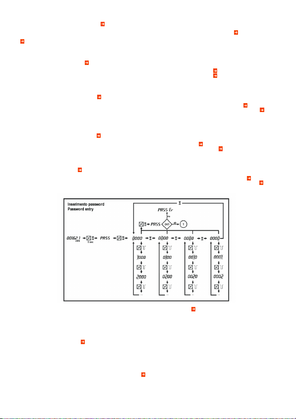
P-01 – Se impostato a 0000 (default) la protezione da password è disabilitata.
P-02 – Definisce la funzione della soglia limite programmabile:
OFF – Soglia programmabile disabilitata;
THR – La soglia programmabile è attivata massima oppure di minima, a seconda
dei valori impostati in P-04 e P-06.
Se P-04 > P-06, allora la soglia limite si attiva con la misura di P-03 > P-04, e si
disattiva quando ritorna ad essere < P-06 (funzione di soglia massima con
isteresi).
Se P-04 < P-06, allora la soglia limite si attiva con la misura di P-03 < P-04, e si
disattiva quando ritorna ad essere > P-06 (funzione di soglia minima con isteresi).
P-03 – Selezione misura alla quale vengono applicate le soglie.
P-04 e P-05 – Soglia e relativo ritardo per attivazione uscita. Nota: le misure vengo-
no aggiornate ed integrate 1 volta al secondo, quindi questo ritardo ha una
variabilità da 0 a + 1 secondo.
P-06 e P-07 – Come sopra, per disattivazione uscita.
P-08 – Definisce il funzionamento del contaore:
OFF – Contaore disabilitato, non viene visualizzato;
ON – Il contaore si incrementa fintanto che l’energy meter è alimentato;
THR – Il contaore si incrementa fintanto che la soglia definita con i parametri pre-
cedenti (P-02, P-03, P-04 e P-05) è attivata.
P-09 – Abilitazione misura e visualizzazione potenza attiva integrata attuale e mas-
sima (max demand).
P-20...P-24 – Parametri per la configurazione porta seriale.
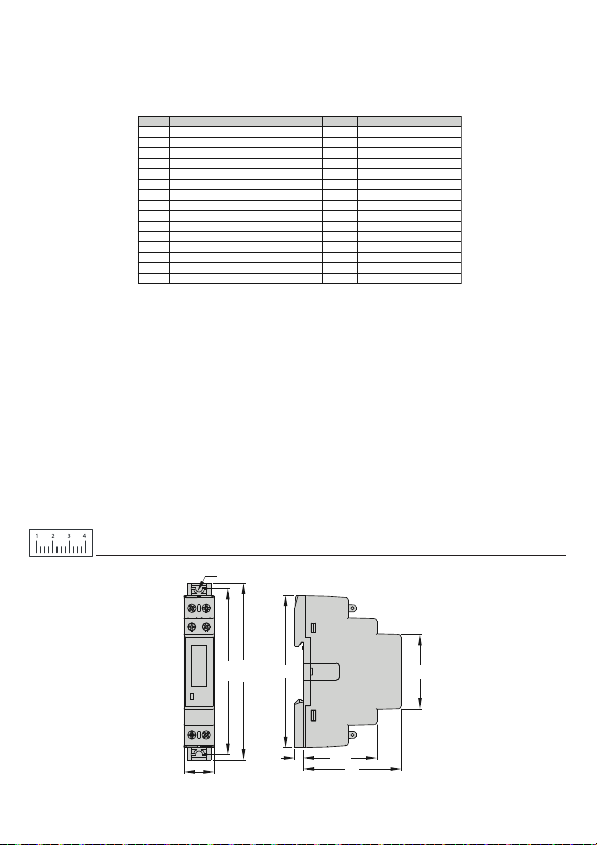
SIGILLI METROLOGICI E MARCATURE
– L’apparecchio certificato MID è identificabile per la presenza degli opportuni
marchi sulla targa (vedere figura).
– Esso è dotato di alcuni accorgimenti che ne impediscono la manomissione:
– 2 sigilli laterali (etichette antimanomissione) che impediscono l’apertura del
contenitore e l’accesso ai circuiti interni;
– coprimorsetti piombabili che quando installati con gli opportuni sigilli
impediscono l’accesso ai morsetti e cablaggi.
– I sigilli sull’ apparecchio devono presentarsi intatti, altrimenti la certificazione
MID dell’apparecchio è da considerarsi decaduta.
– Il numero di serie dell’apparecchio è posto su una apposita etichetta laterale.
P-01 – If set to 0000 (default) the password protection is disabled.
P-02 - Defines the function of the programmable limit threshold:
OFF - Programmable threshold disabled.
THR - The programmable threshold is activated by a maximum or minimum limit,
depending on values programmed in P-04 and P-06.
If P-04 > P-06, then the limit threshold activates when the measure defined by P-03
is higher than P-04, end de-activates when its value becomes less than P-06 (maximum
limit with hysteresis).
If P-04 < P-06, then the limit threshold activates when the measure defined by P-03 is
lower than P-04, end activates when its value becomes higher than P-06 (minimum
limit with hysteresis).
P-03 – Selection of measure to compare with thresholds.
P-04 and P-05 – Threshold and delay for output activation. Note: The measurements are
updated every 1 second, that means that the variability of this delay is in the range from
0 to + 1 second.
P-06 and P-07 – Threshold and delay for output de-activation.
P-08 – Defines the hor counter operation:
OFF – Hour counter disabled. It is not shown on the display.
ON – The hour counter is incremented as long as the energy meter is supplied.
THR – The hour counter is incremented as long as the threshold defined with previous
parameter (P-02, P-03, P-04 and P-05) is active.
P-09 – Enable of calculation and visualization of active energy demand and max demand.
P-20...P-24 – Parameters for serial port configuration.
METROLOGICAL SEALING AND MARKINGS
– The MID certified device is identified by the appropriate markings on the side (see figure)
– It is equipped with anti-tampering solutions:
– two anti-tampering labels that seals the housing, that avoid the possibility to access
the internal circuitry.
– sealable terminal covers that, when installed with proper sealing, eliminate the
possibility to access terminals and wiring.
– The sealings on the device must appear intact, otherwise the MID certification is void.
– The serial number of the device is placed on a side label.
P-01 – Sil est imposé sur 0000 (par défaut), la protection par mot de passe est désha-
bilitée.
P-02 – Il définit la fonction de seuil limite programmable:
OFF - Seuil programmable déshabilité;
THR – Le seuil programmable est activé au maximum ou au minimum selon les valeurs
imposées dans P-04 et P-06.
Si P-04 > P-06, alors le seuil limite s’active avec la mesure de P-03 > P-04 et se
désactive lorsque qu’il retourne < P-06 (fonction de seuil maximal avec hystérésis).
Si P-04 < P-06, alors le seuil limite s’active avec la mesure de P-03 < P-04 et se
désactive lorsque qu’il retourne > P-06 (fonction de seuil minimal avec hystérésis).
P-03 - Sélection de la mesure à laquelle les seuils sont appliqués.
P-04 et P-05 - Seuil et retard correspondant pou l’activation de la sortie. Remarque : les
mesures sont mises à jour et intégrées une fois par seconde: le retard présente donc une
variabilité de 0 à 1 seconde.
P-06 et P-07 - Comme ci-dessus pour la désactivation de la sortie.
P-08 - Définit le fonctionnement du compteur horaire:
OFF – Compteur horaire déshabilité, il n’est pas visualisé;
ON – Le compteur horaire est incrémenté tant que le compteur d’énergie est alimenté;
THR – Le compteur horaire est incrémenté tant que le seuil défini dans les paramètres
précédents (P-02, P-03, P-04 et P-05) est activé.
P-09 = Habilitation de la mesure et visualisation de la puissance active intégrée courante
et maximale (demande max).
P-20...P-24 – Paramètres de configuration du port sériel.
SCELLÉS MÉTROLOGIQUES ET MARQUAGES
– L’appareil certifié MID est identifié par les marques correspondantes sur la plaque
(voir figure).
– Il est équipé de certains dispositifs qui en empêchent l’altération:
– 2 scellés latéraux (étiquettes anti-altération) qui empêchent l’ouverture du boîtier
et l’accès aux circuits internes;
– des cache-bornes plombables qui, s’ils sont montés avec les scellés, empêchent
l’accès aux bornes et aux câblages.
– Les scellés de l’appareil doivent rester intacts ; dans le cas contraire, la certification
MID de l’appareil tombe.
– Le numéro de série de l’appareil est reporté sur l’étiquette latérale correspondante.
P-01 – Si el valor es 0000 (default) significa que la protección mediante contraseña está
deshabilitada.
P-02 – Define la función del umbral límite programable:
OFF - Umbral programable deshabilitado;
THR – El umbral programable se activa al máximo o al mínimo, según los valores
configurados en P-04 y P-06.
Si P-04 > P-06, entonces el umbral límite se activa con la medición de P-03 > P-04,
y se desactiva cuando vuelve a ser < P-06 (función de umbral máximo con histéresis).
Si P-04 > P-06, entonces, el umbral límite se activa con la medición de P-03 < P-04,
y se desactiva cuando vuelve a ser > P-06 (función de umbral mínimo con histéresis).
P-03 – Selección de medida en la cual se aplican los umbrales.
P-04 y P-05 – Umbral y respectivo retraso para activación de salida. Nota: las mediciones
se actualizan e integran 1 vez por segundo, por lo tanto, este retraso tiene una variabilidad
de 0 a + 1 segundo.
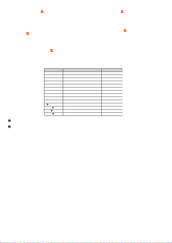
Code Description Default Range
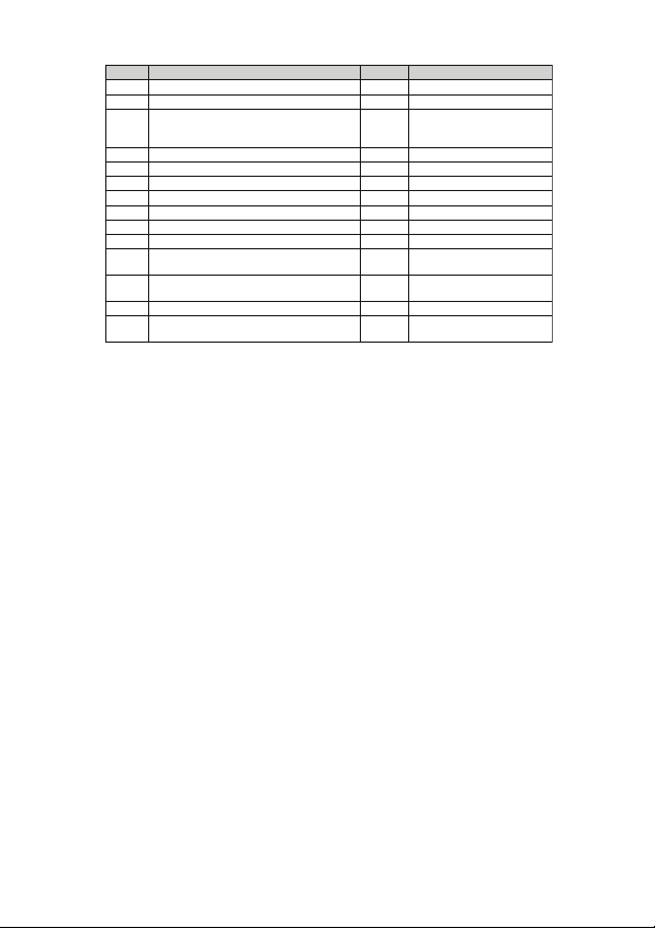
P-01 Password 0000 0000 - 9999
P-02 Programmable limit threshold enable OFF OFF - TH R
P-03 Threshold measure kW 01=kW - 02=kvar - 03=V
04=A - 05=Hz - 06=kWh Part 07=h
Part – 08 kW demand
P-04 ON threshold 100.00 0.00 – 999.99
P-05 ON delay 5s 0 – 9999s
P-06 OFF threshold 50.00 0.00 – 999.99
P-07 OFF delay 5s 0 – 9999s
P-08 Hour counter enable OFF OFF-ON-TH R
P-09 Enable demand measures OFF OFF-ON
P-20 Serial node address 001 001-255
P-21 Serial speed 9600 1200 / 2400 / 4800 / 9600
19200 / 38400
P-22 Data format 8 bit – n 8 bit - no parity / 8 bit, odd
8 bit,even / 7 bit,odd / 7 bit, even
P-23 Stop bits 1 1-2
P-24 Protocol Modbus Modbus-RTU
RTU Modbus-ASCII
TABELLA PARAMETRI DI SETUP
SETUP PARAMETERS TABLE
TABLEAU DES PARAMÈTRES DE SETUP
TABLA DE PARÁMETROS DE SETUP
TABELLE DER SETUP-PARAMETER