Pg 5 of 12
+GF+ SIGNET 5075 Totalizing Monitor Instructions
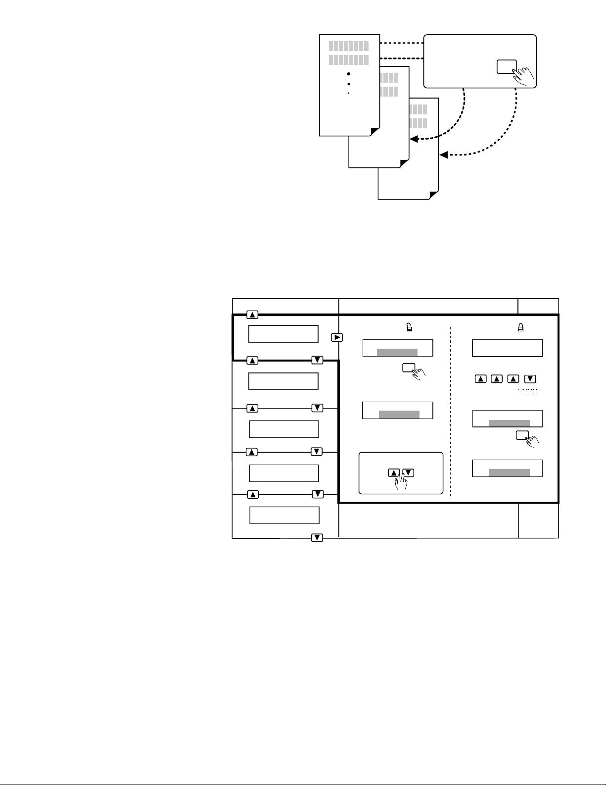
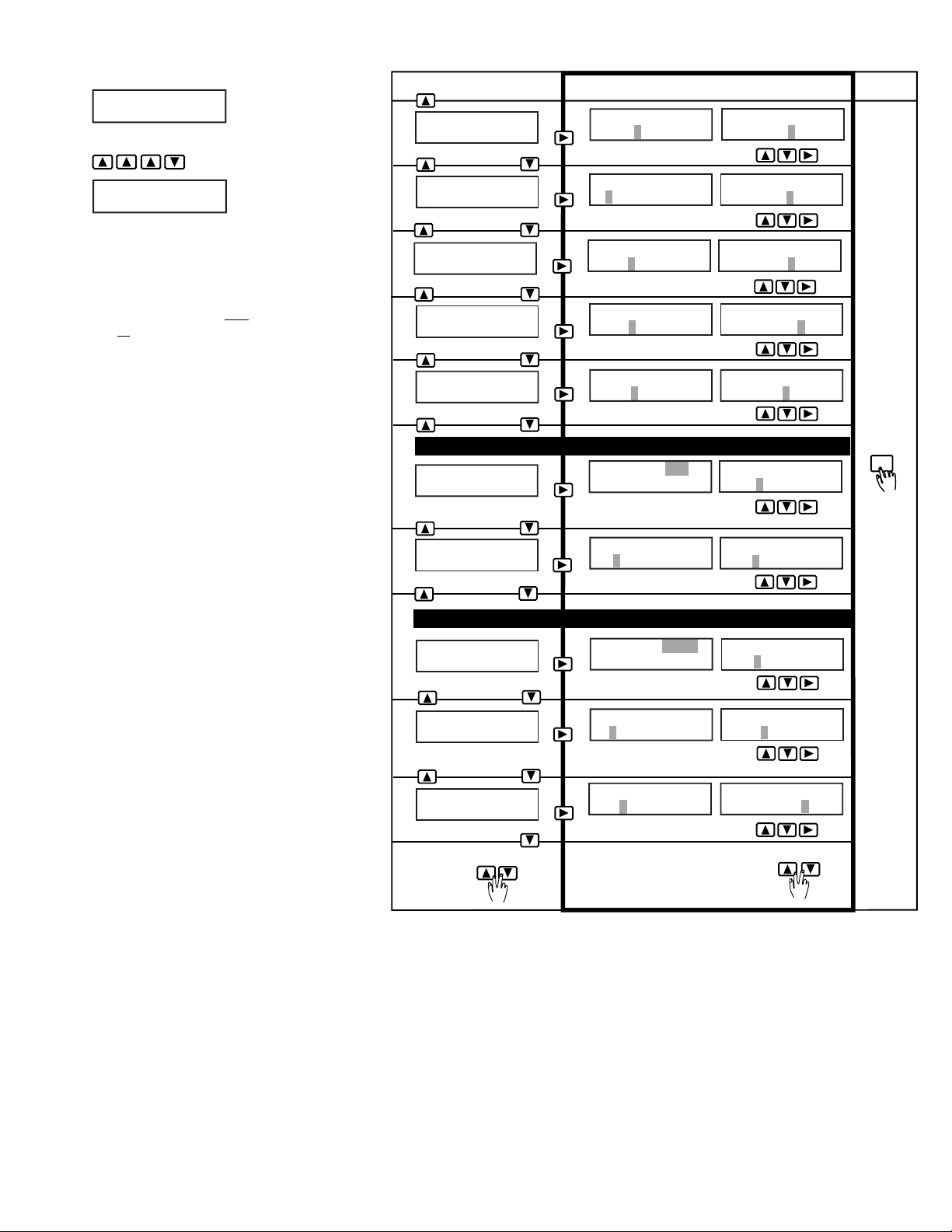
7.2 CALIBRATE Menu
Press and hold ENTER key for 2 seconds:
is displayed.
Press keys in sequence to enter enu:
is displayed.
Menu Settings A - J:
(Factory default displays shown in enu
colu n 1)
A. Sets flow units label (gp ) and ti ebase
(gpm). Flow units label: Aa - Zz, 0 - 9, /
Ti ebase options: h = hours, = inutes,
s=seconds, d = days
B. Sets Min
→
Max eter and dial range, 00.000
to 99999.
C. Sets flow K-Factor: 0.0001 to 99999. (see
technical notes below)
D. Sets 8-digit totalizer units label: Aa - Zz, 0 -
9, / (does not affect totalizer display or
outputs)
E. Sets totalizer K-Factor: 0.0001 to 99999.
(see techical notes below)
F. Sets auxiliary output ode Low or High, and
flow rate setpoint, 0.0000 - 99999.
G. Sets auxiliary output hysteresis, 0.0000 -
99999. (Set to zero to disable hysteresis
feature)
H. Sets auxiliary output pulse volu e setpoint,
0.0001 - 99999. Set to 1.0000 (factory
default) to enable totalizer function.
I. Sets auxiliary output pulse width, 0.10 - 999.
seconds.
J. Sets user defined setup date for
aintenance records. This feature is not an
internal ti er or calender.
Technical Notes:
The flow and total K-Factors are independent of
each other. The K-Factor settings represent the
nu ber of pulses generated by the +GF+
SIGNET flow sensor for each engineering unit of
fluid easured (published in flow sensor
anual).
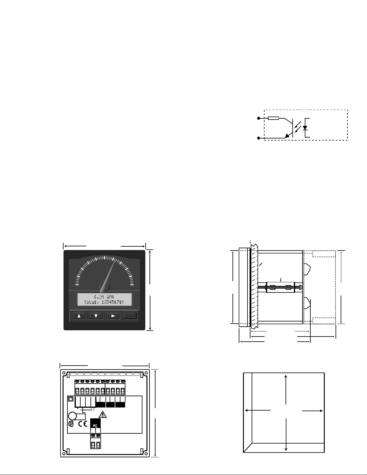
Aux Out Hys:
1.5000 GPM
Last CAL:
01-01-98
Flow K-Factor:
32.480
Flow K-Factor:
60.000
Min→Max: GPM
00.000→100.00 Min→Max: GPM
00.000→500.00
Flow Units:
mL/m
Total K-Factor:
60.000
quick
press
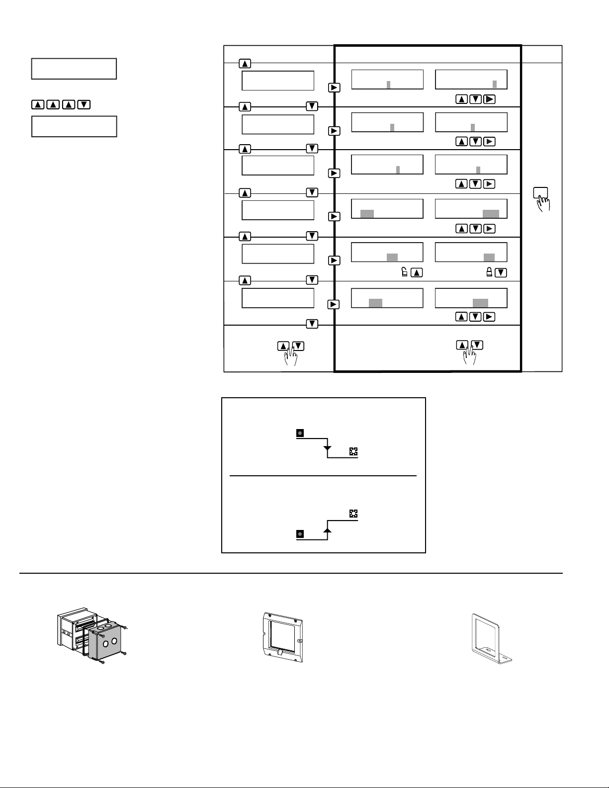
To return to
VIEW enu: quick
press
To restore original value:
Or press keys a second
ti e to exit enu:
Mode (top row)
Setpoint (botto row)
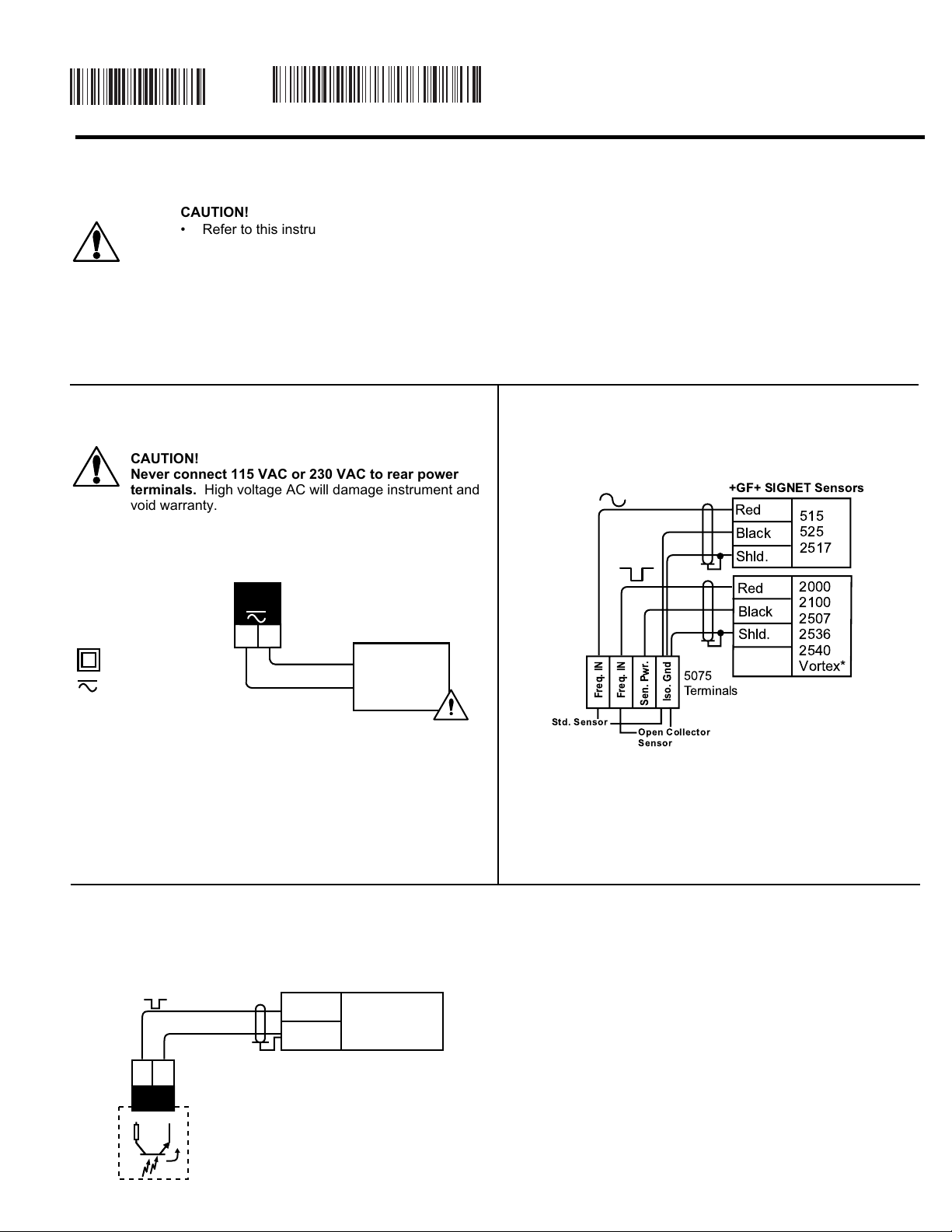
Aux Output Low o High Mode Selected
Open-Collecto Output F equency Selected
A.
B.
D.
E.
F.
G.
J.
ENTER
"SAVING"
displayed
Choose: Change: Save:
To J
To A
Flow Units:
GPM >
Min
→
Max: GPM
0.000
→100.00
>
Total Units:
Gallons > Total Units:
Gallons Total Units:
Gal x 10
Total K-Factor:
60.000 > Total K-Factor:
324.80
Aux Out: Low
1.0000 GPM >
Mode (top row)
Divisor (botto row)
H.
Aux Out: Pulse
1.0000 Gallons > Aux Out: Pulse
1.0000 Gallons Aux Out: Pulse
125.00 Gallons
I.
Aux Out Hys:
0.0000 GPM > Aux Out Hys:
0.0000 GPM
Aux Out: Low
1.0000 GPM Aux Out: Low
10.500 GPM
Last CAL:
01-01-99 >
Flow Units:
_GPM
AuxOut PlsWidth:
0.10 Seconds >
C.
Flow K-Factor:
60.000 >
Mode (top row)
Divisor (botto row)
AuxOut PlsWidth:
0.10 Seconds AuxOut PlsWidth:
0.25Seconds
Last CAL:
02-05-98
CALIBRATE: ----
Enter Key Code
CALIBRATE: XXXX
Enter Key Code