3
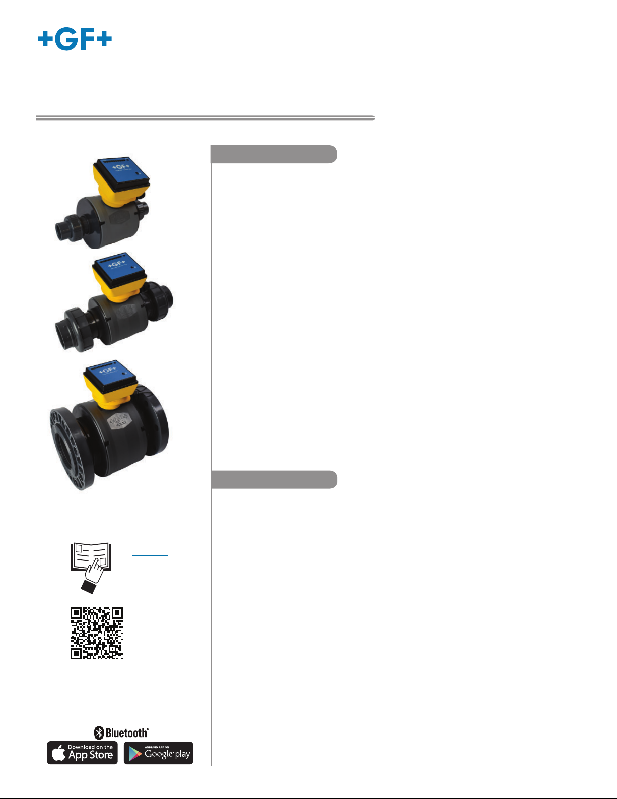
Signet 2580 FlowtraMag Meter
Specifi cations
General
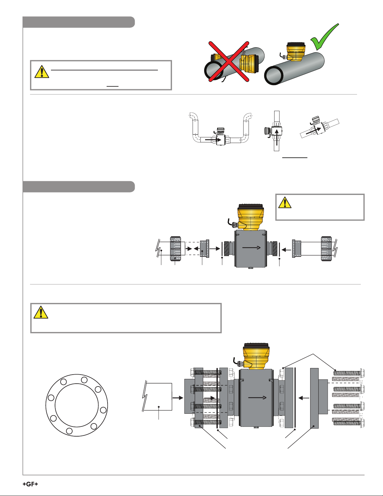
Pipe Size Range ..................... 1", 2" and 4" (ASTM only)
Flow Range
Minimum .............................. 0.02 m/s (0.07 ft/s)
Maximum ............................. 10 m/s (33 ft/s)
3-2580-P-T-010 ....................... 0.53 to 266.35 L/min
(0.14 to 70.36 gal/min)
3-2580-P-T-020 ....................... 2.23 to 1112.60 L/min
(0.59 to 293.92 gal/min)
3-2580-P-T-040 ....................... 8.72 to 4357.83 L/min
(2.30 to 1151.22 gal/min)
Repeatability ...........................± 0.5% of reading @ 25 °C (77 °F)
Accuracy ................................. ± 1% + 0.01 m/s (0.033 ft/s)
(reference condition 50 μS/cm and
water based)
Minimum Conductivity ............. 20 μS/cm - water based
Suspended Solids ................... 5%
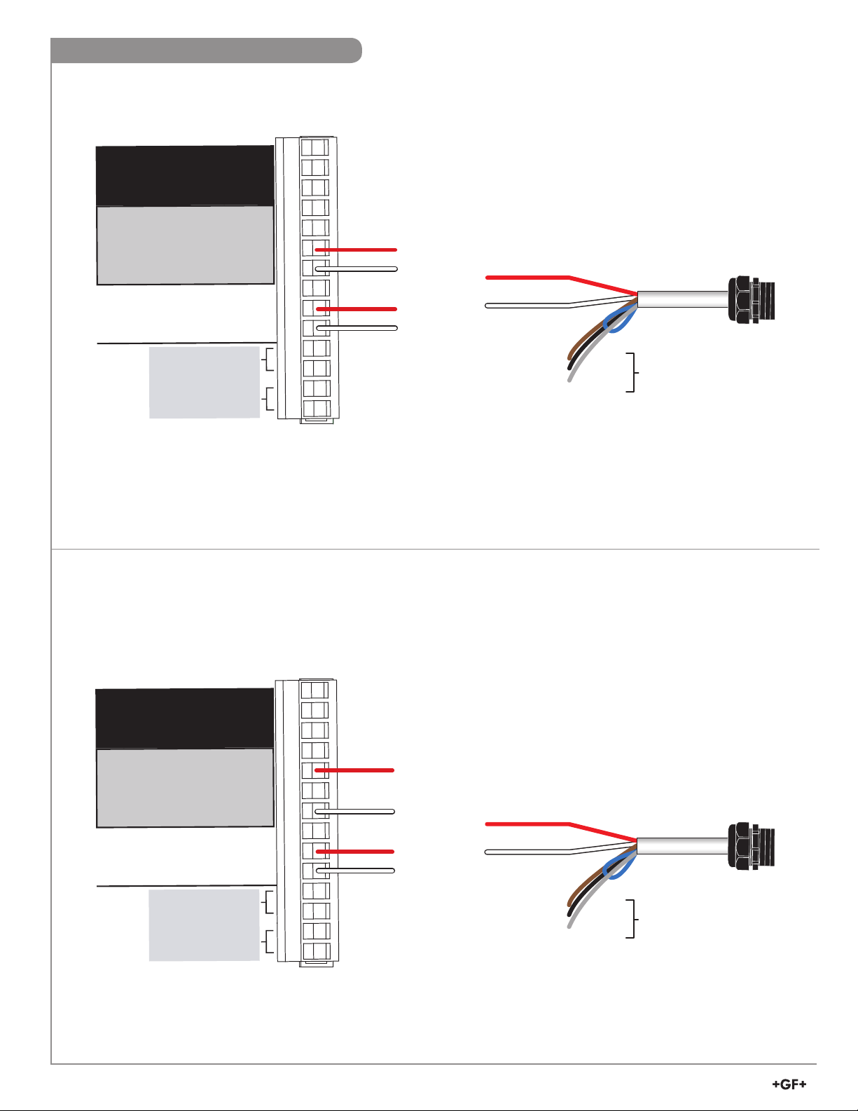
Power Cable Wire ................... 7.6 m (25 ft) 2-conductor shielded
Output Cable Wire .................. 7.6 m (25 ft) 5-conductor shielded
• May be extended up to 305 m (1000 ft), special order only
Wetted Materials
Flow Tube Body ...................... PVC
Electrode ................................. Titanium, grade 2
O-rings ..................................... FKM
Electrical
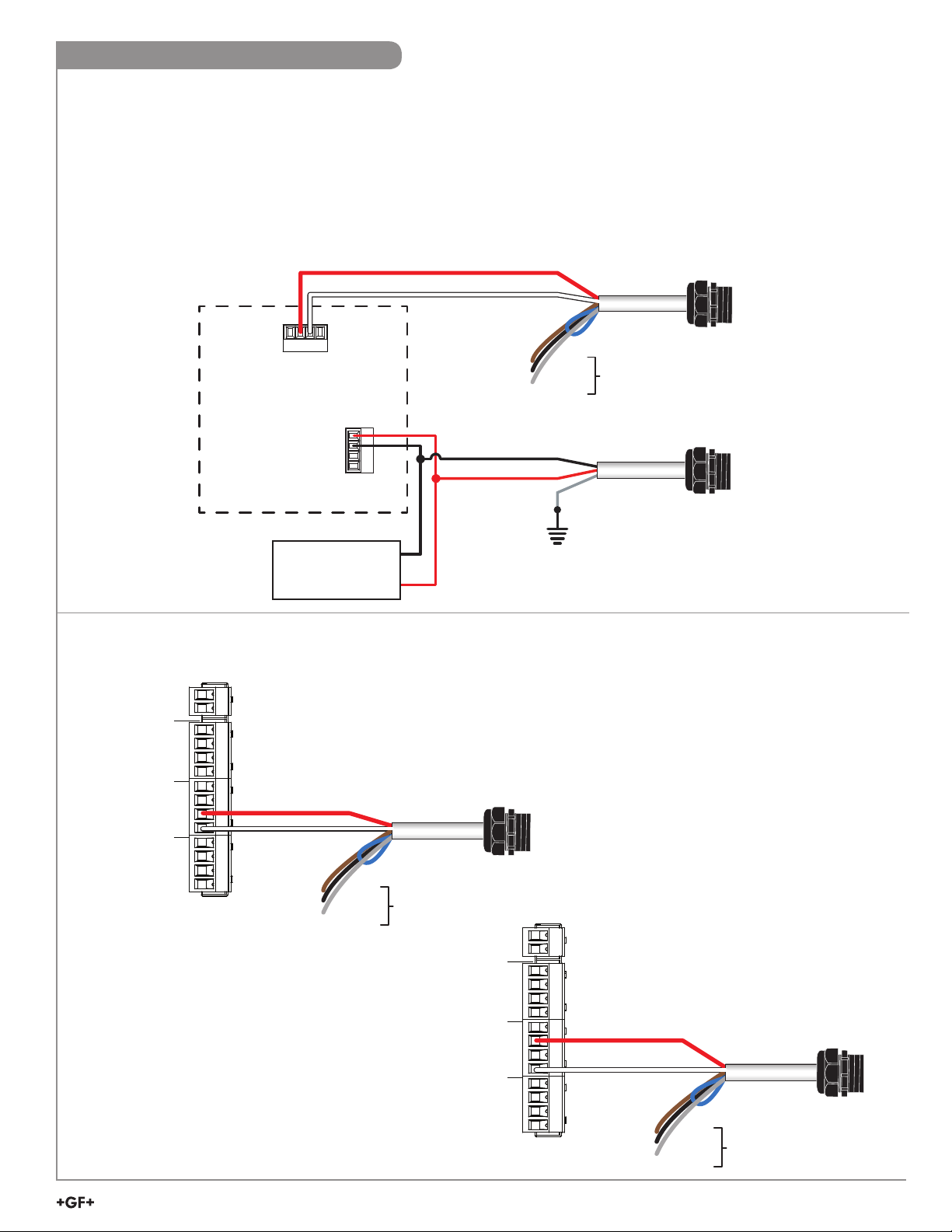
Power Requirements
DC Power
(Functional Rating) .................. 24 VDC, max 24W (12 to 32 VDC)
Reverse Polarity Protected ..... Up to 35 VDC
Over-Voltage
Maximum Rating 35 VDC
Please use a power supply that has been IEC 60950/61010/60601
Certifi ed and will not be used outside of its electrical ratings and
matches the environmental conditions of the fl ow meter.
Current Output
Passive (low power) 4 to 20 mA per ANSI-ISA 50.00.01 class H
Active Output ........................... 4 to 20 mA
Passive Loop Voltage ............. 12 to 32 VDC
Loop Accuracy......................... ± 32 μA (25 °C @ 24 VDC)
Loop Resolution ...................... 5 μA
Loop Span ............................... 3.8 mA to 21 mA
Error condition ......................... None, 3.6 mA or 22 mA
Max. Cable .............................. 300 m (1000 ft)
Max. Loop Resistance ............ 600 Ω @ 24 VDC
Compatible with PLC, PC or similar equipment
Frequency Output
Frequency ............................... 5 to 24 VDC, 50 mA max.
Frequency Range ................... 0 to 1500 Hz
Max. Pull-up Voltage ............... 30 VDC, 10k pull-up recommended
Compatible with Signet 8900, 9900, 9950, and
0486 Profi bus Concentrator
Digital (S
3
L) Output
Digital (S
3
L) ............................. 4.5 to 5.5 VDC
Serial ASCII, TTL level 9600 bps
Compatible with Signet 8900, 9900, 9950 and
0486 Profi bus Concentrator
Max. Cable Length .................. Application dependent
The Bluetooth® word mark and logos are registered trademarks owned
by Bluetooth SIG,Inc. and any use of such marks by Georg Fischer is
under license. Other trademarks and trade names are those of their
respective owners.
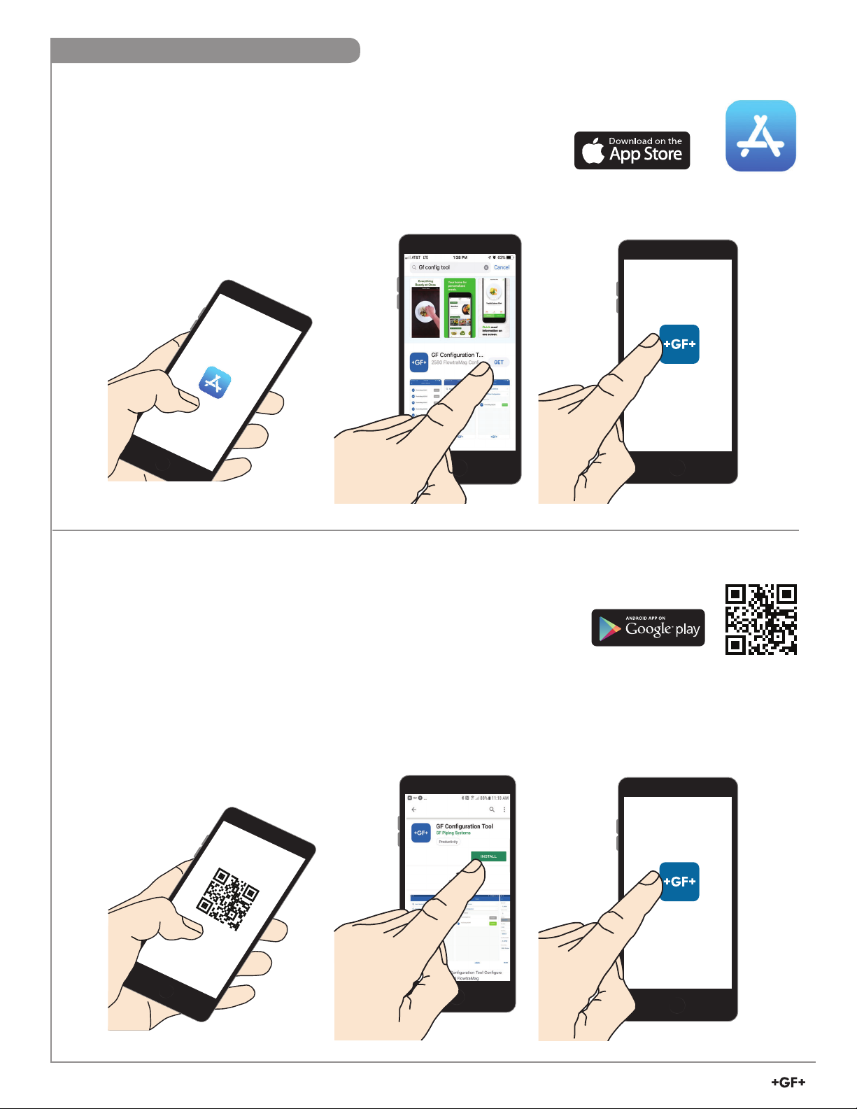
Sensor Confi guration
GF Confi g Tool Bluetooth™ App
2.4 GHz RF Transceiver Compatible with Bluetooth®
Low Energy (BLE) 4.2 Specifi cation
GF Confi g Tool App available in iOS and Android
App Stores
0252 Confi guration Tool
Environmental Requirements
Enclosure ................................ NEMA 4X / IP65
Relative Humidity .................... 0 to 95% (non-condensing)
Altitude .................................... 4,000 m (13,123 ft)
Storage Temperature .............. -10 °C to 60 °C (14 °F to 140 °F)
Operating Temperature
Ambient ............................... -10 °C to 60 °C (14 °F to 140 °F)
Media .................................. 0 °C to 60 °C (32 °F to 140 °F)
UL environmental Rating ..... UL 50, Type 6P Storage
Maximum Operating
Pressure .................................. 10 bar @ 23 °C (145 psi @ 73 °F)
1" and 2" .............................. 3.5 bar @ 60 °C (51 psi @ 140 °F)
4" ......................................... 2.27 bar @ 60 °C (33 psi @ 140 °F)
Shipping Weights
3-2580-P-T-010 ....................... 3.4 kg (7.5 lbs)
3-2580-P-T-020 ....................... 4.46 kg (9.83 lbs)
3-2580-P-T-040 ....................... 8.3 kg (18.28 lbs)
Sensor Weights
3-2580-P-T-010 ........................ 2.65 kg (5.84 lbs)
3-2580-P-T-020 ........................ 3.71 kg (8.16 lbs)
3-2580-P-T-040 ........................ 6.26 kg (13.79 lbs) - (excludes
mounting hardware)
Standards and Approvals
CE
UL, CUL Recognized Component
NSF (Pending)
RoHS compliant
Manufactured under ISO 9001 for Quality, ISO 14001
for Environmental Management and OHSAS 18001 for
Occupational Health and Safety.
China RoHS (visit gfsignet.com for details)
Declaration of Conformity according to FCC Part 15
This device complies with Part 15 of the FCC rules.
Operation is subject to the following two conditions:
(1) This device may not cause harmful interference, and,
(2) This device must accept any interference received, including
interference that may cause undesired operation.