3 Installation
3.1 Mounting master on the wall
The housing of the master is attached to the wall using 4 eyelets (1).
Drill 4 dowel holes with a diameter of 6 mm into the wall according to dimensional draw-
ing and insert the supplied dowels (2).
Use a Phillips screwdriver to screw on the master with the 4 screws provided (3).
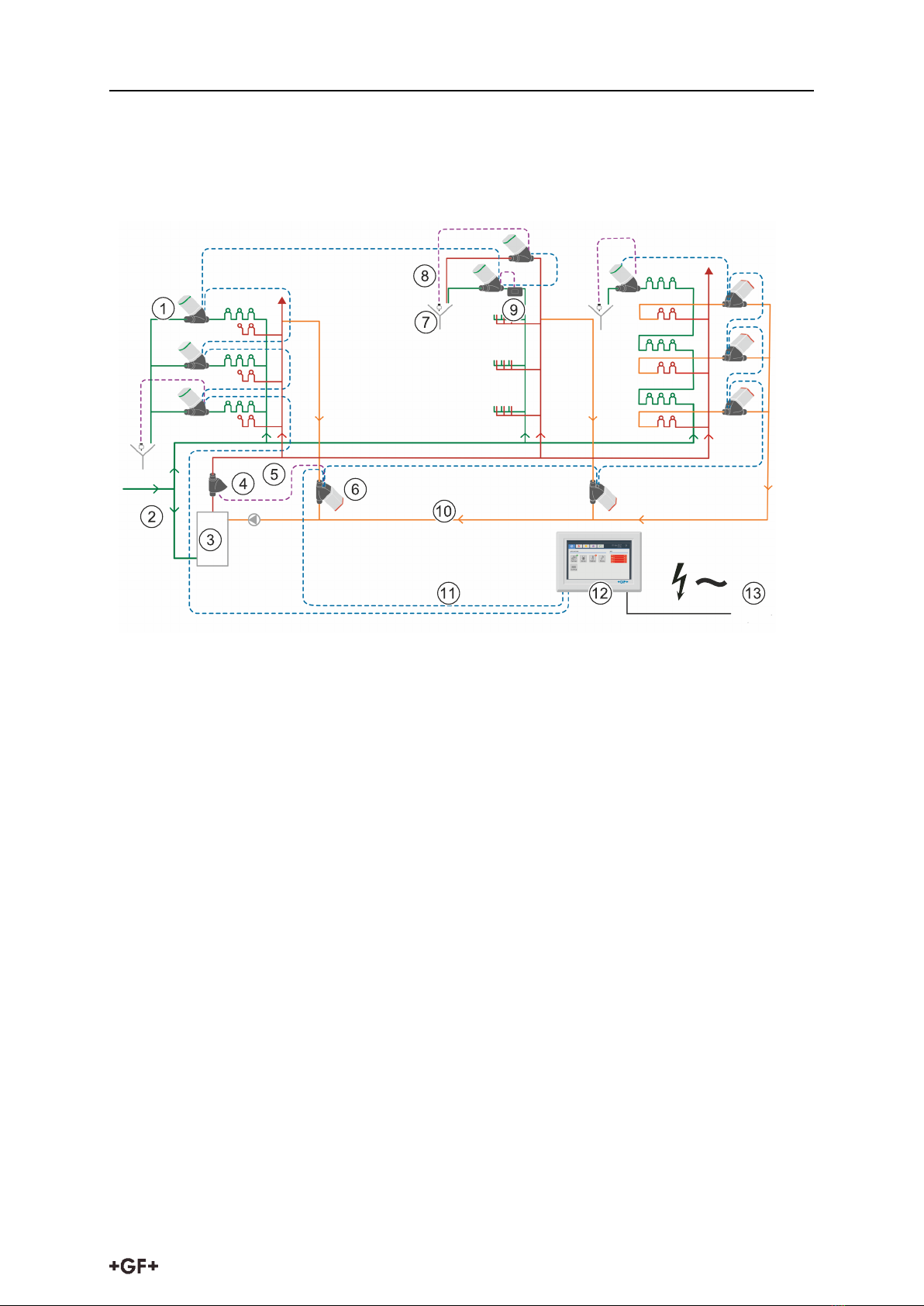
3.2 Cabling master with valves
The connecting cables include 2 lines for the voltage supply and 2 signal lines. The two cable
ends are equipped with the same female plug-in connectors. They are secured to prevent rota-
tion and their M12 knurled screws ensure a reliable hold, even in harsh environments.
Non-approved components can cause malfunctions!
Components must not be modified and connecting cables or distributors for star topology
cabling must not be installed at any time!
Always interconnect master, valves and, where required, powerboxes in series, i.e.
one behind the other, to the components specified by the manufacturer!
10