GF 2290 User manual

Instruction Manual
GF Piping Systems
2290 Non-contact Radar Level Transmitter

2

3
Original instruction manual
Follow the instruction manual
The instruction manual is part of the product and is an important element of the safety
concept.
Read and follow the instruction manual.
Always keep the instruction manual available with the product.
Pass on the instruction manual to all subsequent users of the product.

4
Contents
Original instruction manual ............................................................................................................ 3
Contents........................................................................................................................................... 4
1Intended use .......................................................................................................................... 6
2About this document ............................................................................................................. 6
2.1 Warnings ................................................................................................................................ 6
3Safety and responsibility ....................................................................................................... 6
4Transport and storage........................................................................................................... 7
5Design and function............................................................................................................... 7
5.1 Function ................................................................................................................................. 7
5.2 Principle of operation............................................................................................................ 7
6Technical data........................................................................................................................ 9
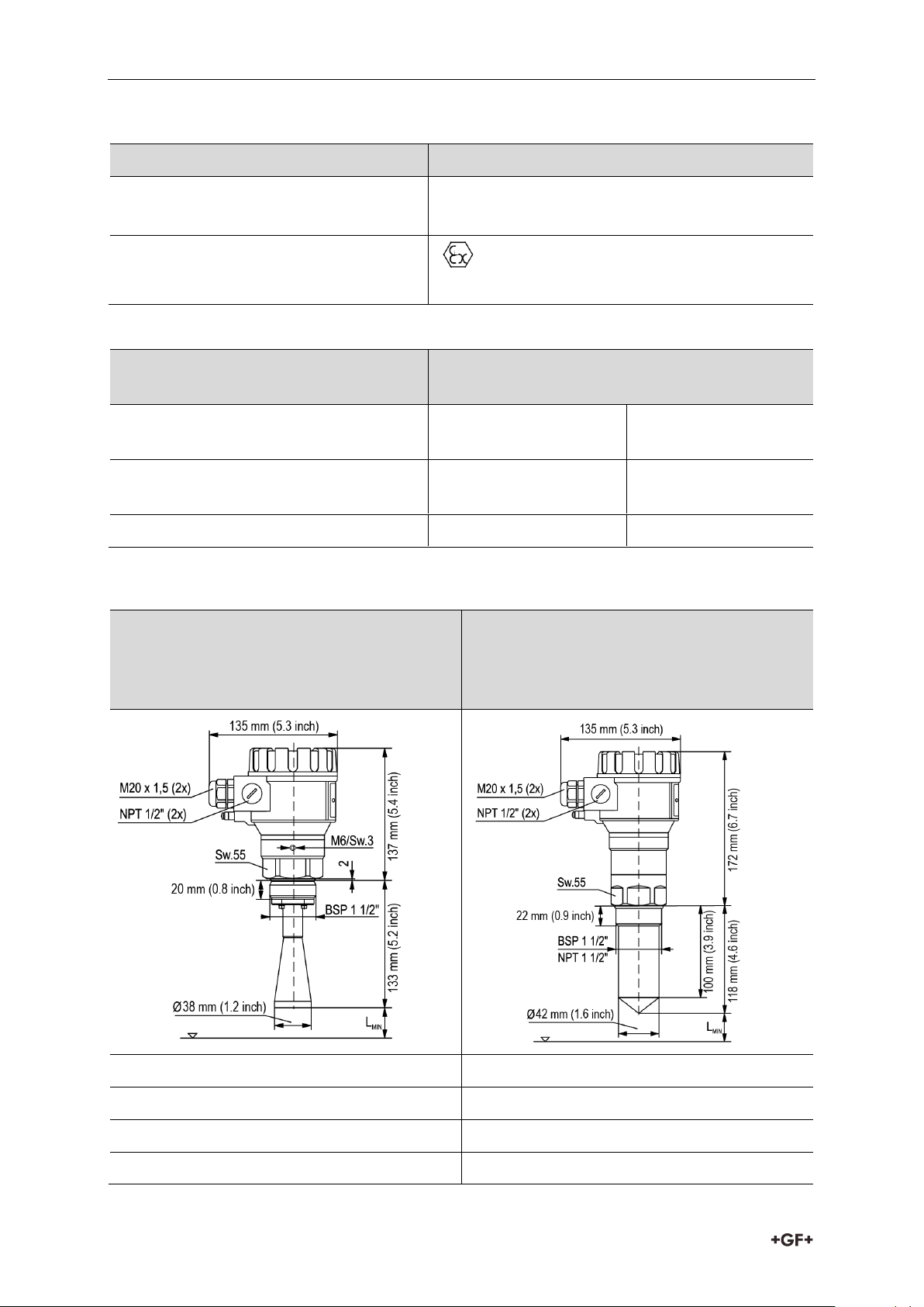
6.1 Dimensions ...........................................................................................................................10
6.2 Determining the maximum measuring range ....................................................................11
7Conditions of safe operation ................................................................................................12
8Installation ............................................................................................................................12
8.1 Mounting ...............................................................................................................................12
8.2 Wiring ....................................................................................................................................14
8.2.1 Wiring of the devices ............................................................................................................15
8.2.2 Determine the appropriate power supply voltage ..............................................................16
8.3 Loop current checking with hand instrument ....................................................................17
9Programming 2290 Level Transmitter ...............................................................................18
9.1 The display unit.....................................................................................................................18
9.1.1 Information Screens.............................................................................................................20
9.1.2 Echo Map...............................................................................................................................21
9.2 Programming with the display module...............................................................................21
9.2.1 Components of the programming interface .......................................................................21
9.2.2 Menu structure .....................................................................................................................23
9.3 Programmable features description...................................................................................23
9.3.1 Basic measurement setting.................................................................................................23
9.3.2 Output setup..........................................................................................................................25
9.3.3 Digital output ........................................................................................................................26
9.3.4 Optimization..........................................................................................................................26
9.3.5 Calculations ..........................................................................................................................29
9.3.6 Service ..................................................................................................................................32
10 Repair and Maintenance ......................................................................................................34

5
11 Accessories...........................................................................................................................34
12 Error codes ...........................................................................................................................34
13 2290 W-100 Parameter table ...............................................................................................35
14 Menu map .............................................................................................................................38
15 Removal ................................................................................................................................41
16 Disposal.................................................................................................................................41

Intended use Instruction manual
6
1Intended use
The GF type 2290 non-contact microwave level transmitters provide the most advanced, new
generation measurement technique of the industrial process automation field. The 2290 is an
ideal solution for high precision level transmitting of liquids, slurries, emulsions and other
chemicals in a wide range of applications, such as food, energy, pharmaceutical and the
chemical industry, and even in naval applications with mm accuracy range and high
measuring stability.
2290 is able to provide an excellent non-contact level measurement for those substances
which tend to steam, or for liquids with a gas layer. Since microwaves do not need a defined
propagation media, the 2290 is applicable in a vacuum.
2About this document
2.1 Warnings
This instruction manual contains warning notices that alert you to the possibility of injuries or
damage to property. Always read and pay attention to these warnings!
Risk of fatal or serious injury!
There is a risk of fatal or serious physical injury if warnings are ignored!
Danger of personal injury!
Failure to comply leads to a risk of personal injury!
Risk of damage to property!
Failure to comply leads to a risk of damage to property (loss of time, loss of data, device
fault etc.)!
3Safety and responsibility
Only use the product for the intended purpose, see Intended Use.
Do not use any damaged or faulty product. Sort out any damaged product immediately.
Have the product and accessories installed only by persons who have the required
training, knowledge or experience.
Regularly train personnel on all questions regarding the local regulations applying to
occupational safety and environmental protection, especially for pressurized tanks.

Instruction manual Transport and storage
7
4Transport and storage
Protect the product against external forces during transport (impacts, knocks, vibrations
etc.).
Transport and / or store the product unopened in its original packaging.
Protect the product from dust, dirt, moisture as well as heat and ultraviolet radiation.
Ensure that the product is not damaged either by mechanical or thermal influences.
Before assembling, check the product for damage during transport.
5Design and function
5.1 Function
5.2 Principle of operation
The reflection of the emitted microwave varies in quality depending on the relative dielectric
constant of the measured medium. The ideal condition of microwave level measurement is
that the relative dielectric constant (εr) for the medium should be greater than 1.9.
The operation of the non-contact microwave level transmitters is based on the measurement
of the time of flight of the reflected signals, so-called Time Domain Reflectometry (TDR)
method.
The propagation speed of microwave impulses is practically the same in air, gases and in
vacuum, independently from the process temperature and pressure, so the measured
distance is not affected by the physical parameters of medium to be measured.

Design and function Instruction manual
8
The 2290 level transmitter is a Pulse Burst Radar operating at 25 GHz (K-band) microwave
frequency.
The 25 GHz models’ most noticeable advantage over the lower frequency (5-12 GHz) radars
are the smaller antenna size, the better focusing, lower dead-band and smaller transmission
angle.
The level transmitter emits nanosecond length impulses from the antenna, and part of the
emitted energy reflects back from the measurement surface, the strength of the reflect
varies on the medium being measured. The time of flight of the reflected signal is measured
and processed by the electronics, and then this is converted to distance, level or volume
proportional data.

Instruction manual Technical data
9
6Technical data
Data
Kv value
Measured values
Level, Distance; Calculated values: Volume, Mass
Frequency of the measuring signal
~25 GHz (K-band)
Measuring range
0.2 m –18 m (0.65 ft –59 ft) (depending on rof the process
liquid)
Linearity error (as per EN 61298-2)
< 0.5 m: 25 mm (< 1.6 ft: 0.9 inch);
0.5 –1 m: 15 mm (1.6 –3.2 ft: 0.6 inch);
1 –1.5 m: 10 mm (3.2 –4.9 ft: 0.4 inch);
1.5 –8 m: 3 mm (4.9 –26.3 ft: 0.1 inch);
> 8 m: 0.04% (> 26.3 ft: 0.04%) of the measured distance
Minimal beam angle
19°
Minimal dielectric constant rof the
medium
1.9 (refer to range diagram below)
Resolution
1 mm (0.04 inch)
Temperature error (as per EN
61298-3)
0.05% FSK / 10 °C (50 °F);
-20 °C… +60 °C (-68 °F… +140 °F)
Power Supply voltage
20 V …36 V DC
Output
4 –20 mA + HART
Output Display
64 x 128 Dot Matrix LCD Graphical display unit
Measuring frequency
10…60 sec as per the application settings
Antenna diameter
38 mm (1 ½”)
Antenna material
Horn: Stainless Steel; enclosure oprtions: PP or PTFE
Process Media
-30 °C… +100°C (-22 °C… +212°C), (up to 120 °C
(248 °F) for max. 2 min); with PP antenna enclosure: max.: 80
°C (176 °F)
Max. media pressure
25 bar at 120°C (248 °F); with plastic antenna enclosure: 3 bar
at 25 °C (77 °F)
Ambient temperature
-20 °C… +60 °C (-4 °F… 140 °F)
Process Connection
DN 40 / 1 ½” BSP, 1 ½” NPT“ thread
Ingress protection
IP 67
Electrical connection
2x M 20 x 1.5 cable glands + internal thread for 2x ½” NPT
cable protective pipe, cable outer diameter: 7 … 13 mm
(0.3 … 0.5 inch), wire cross section: max. 1.5 mm2(AWG 15),
wire cross section: max. 1.5 mm2
Electrical protection
Class III
Housing material
Plastic (/PBT)
Sealing
FPM
Communication certifications
R&TTE, FCC
Material of wetted parts
PP / PTFE /Stainless Steel 316 Ti

Technical data Instruction manual
10
Explosion Protection, Ex markings, Ex limit data
Type
2290
IECEx (ia)
Ex ia IIB T6…T5 Ga/Gb
Li: 200µH Ci: 16nF Ui:30V Ii:140mA Pi:1W
ATEX (ia)
II 1/2 G Ex ia IIB T6…T5 Ga/Gb
Li: 200µH Ci: 16nF Ui:30V Ii:140mA Pi:1W
Temperature limit data for hazardous atmospheres:
Temperature data for hazardous gas
atmospheres (II B group)
2290
Maximum permissible medium
temperature at the antenna
+80°C (176 °F)
+80°C (176 °F)
Maximum permissible surface
temperature at the process connection
+75°C (167 °F)
+80°C (167 °F)
Temperature class
T6
T5
6.1 Dimensions
Plastic Housing,
1½” Horn antenna
2290-S-DB2-18+2290-F-ENC-B2/N2
2290-S-DN2-18
Plastic Housing,
1½” PP encapsulated antenna
2290-P-1DB2-18
2290-P-1DN2-18
1.4571, antenna, PTFE antenna enclosure
PP
1½” BSP, 1½” NPT
1½” BSP, 1½” NPT
Lmin: 200 mm (7.9 inch)
19°
19°

Instruction manual Technical data
11
6.2 Determining the maximum measuring range
The maximum measuring range of the 2290 radar is dependent upon the circumstances of
the application environment and on the selected type of antenna enclosure. Depending on the
relative dielectric constant of the measuring medium and the process conditions the
maximum measurement range (achievable under the reference conditions) may decrease by
even 85%.
The maximum measuring distance is illustrated in the above diagram for various Dielectric
Constants. This diagram is based upon the following conditions, liquids with still surface, no
foam, vapors, and ideally a slow (<5m/h, 16.4 ft/h) rate of level change.
Depending on the process conditions or the plastic antenna enclosure the following typical
reducing factors are recommended to be considered in order to calculate the maximum
measuring range. When more than one reducing factors occur at the same time then all the
factors should be included for the calculation:
Process Condition
Reflection reduction
in Amplitude
Max. measuring distance
decrease by
Reducing
Factor
Slow mixing or slightly
waving
2…6 dB
20-50%
0.8…0.5
Foaming
2…6 dB
20-50%
0.8…0.5
Fast mixing, vortex
8…10 dB
60-70% (the measurement
might be completely terminated)
0.4…0.3
Vapors, Steam,
Condensation
3…10 dB
30-70% (the measurement
might be completely terminated)
0.7…0.3
PP antenna enclosure
2 dB
20%
0.8
PTFE antenna enclosure
1 dB
10%
0.9

Conditions of safe operation Instruction manual
12
7Conditions of safe operation
To avoid the danger of electrostatic charge accumulation, in case of the type 2290 (with plastic
electronic housing or plastic antenna enclosure) the following safety rule shall be observed:
The measured medium should be an electrostatic conductor and the electrical resistivity
of the measured medium cannot exceed 104.
The speed and the method of the filling and emptying process should be chosen properly
according to the measured medium.
The plastic antenna enclosure should only be wiped cleaned with a wet cloth.
Meeting the requirements of the technological process
Please carefully consider that all parts of the instrument which can possibly to come into
contact with the measured medium –including the transducer, the sealing and any other
mechanical parts –should meet all requirements of the applied technological process, such
as the process pressure, temperature and chemical effects of the used technologies.
FCC Radio license
This device complies with Part 15 of the FCC Rules. Operation is subject to the following two
conditions:
(1) This device may not cause harmful interference, and
(2) This device must accept any interference received, including interference that may cause
undesired operation.
Changes or modifications not expressly approved by the manufacturer could void the
warranty and user's authority to operate the equipment.
8Installation
8.1 Mounting
When choosing the installation place please ensure proper space for accessing the unit for
calibration, verification, and or maintenance service.
Placement
The ideal position for the 2290 is on = (0.3 … 0.5) xR
(in case of cylindrical tank). It is highly
recommended to consider the beam cone of 19°.
The distance between the sensor and the tank wall
should be at least 200 mm (7.9 inch). If the unit is
installed into dome top or spherical tank,
unwanted multiple reflections may appear, which
can cancel each other and the measuring signal
out, this way it can interfere the measurement.

Instruction manual Installation
13
Moving liquid surface
Waving, vortex or strong vibration effects can have
negative influence on the measurement accuracy
and the maximum measuring range. To avoid
these effects, the mounting placement should be
as far as possible from the sources of these
disturbing effects. According to measurement
experiences the maximum measuring distance
may decrease by 60-70% when the liquid surface
is vortexing. For this reason the device should be
mounted as far as possible from the filling stream
or the tank outlet.
Foaming
Filling, stirring or any other
processes in the tank can generate
dense foams on the liquid surface,
which may considerably damp the
reflected signals. According to
measurement experiences, in these
cases the maximum measuring
distance can decrease by as much
as 50%.
Fumes, Vapours
If the measured medium or its
foam can reach the antenna or
the measured medium is highly
fuming, these cases build-ups
can form on the sensor, which
may result unreliable level
measurement.
Sensor alignment
The antenna face should be
parallel to the medium
surface within 2-3°.
Temperature
To avoid overheating
the instrument should
be protected against
direct sunshine.
Obstacles
Prior to the installation make sure
that no objects (cooling pipes,
bracing elements, mixer shaft,
other sensors such as pH,
Temperature, et cetera) cross the
microwave signals. Especially in
case of extraordinary large silos
bracing elements and other
structural obstacles may cause
false reflections which can be
damped in most cases: a small bent
metal deflector plate mounted
above the obstacle can disperse the
microwave signals and eliminates
the false reflections which disturb
the reliable measurement.
If there is no possible mechanical
solution to avoid these kinds of false
reflections, the programming of the
instrument allows blocking out the
obstacles.
Polarization plane
The emitted radar impulses of
2290 are electromagnetic
waves. The orientation of the
polarization plane is the same
as for the electric wave
component of the electro-
magnetic wave. The rotation of
the polarization plane
compared to the tank position
could be useful (for example to
avoid disturbing reflections) in
certain applications. To rotate
the polarization plane loosen
the M6 hex socket set screw
above the process connection
and rotate the instrument.
Then tighten the unit by the
screw.

Installation Instruction manual
14
Empty tank
Especially in case of standing tanks
with hemispherical bottom and in
case of tanks which have any
equipment inside at the bottom (e.g.
heating element, mixer) wrong level
measurement may happen when
the tank is totally emptied. The
reason for this measurement error
is that the tank bottom or the
objects at the bottom disperse or
reflect the emitted microwave
signals. Furthermore these weak
and dispersed signals may interfere
with Transmitter performance.In
order to perform reliable level
measurement there should be at
least 100 mm liquid level above the
disturbing objects at the bottom or
above the hemispherical tank
bottom.
Socket, nozzle
The process connection should be implemented
that the antenna end should protrude at least
10 mm out of the socket.
8.2 Wiring
The instrument operates from 20 … 36 V galvanic isolated and not grounded DC power supply
in two-wire system. The voltage value measured on the terminal of the instrument should be
minimum 20 V (in case of 4mA)! In case of using HART interface a minimal 250 Ohm
resistance should be maintained within the network. The instrument should be wired with
shielded cable led through the cable gland. The wiring of the cables can be done after
removing the cover of the instrument and the display unit.

Instruction manual Installation
15
The grounding screw on the housing of the transmitter should be connected to the
equipotential network. Resistance of the EP network should be connected to the system
ground with the same potential as the rest of the network. The shield wire of the signal
cable should only be grounded at the control panel, and left floating/ insulated at the sensor.
To avoid electrical noise, route signal cable away from cables carrying AC voltages.
Especially the inductive couplings of AC harmonics can be critical (which are present at
frequency converter control) because even cable shielding does not supply effective
protection against these cases.
The instrument may be damaged by electrostatic discharge (ESD) via its terminal,
thus apply the precautions commonly used to avoid electrostatic discharge e.g.
By touching a properly grounded point before removing the cover of the enclosure.
A possible electrostatic discharge can cause damage for the instrument. Do not touch the
internal terminals!
Water / Vapor
To achieve suitable ingress protection GF recommends using the suggested
cable outer diameter and properly secure the cable gland.
GF also recommends routing the connecting cables downwards to divert
rain water or condensed water away from Transmitter. This is needed in
case of outside installations and some special applications where there is
very high humidity or the possibility of water condensation is quite high (for
example in cleaning, purification processes, in cooled and / or heated tanks).
8.2.1 Wiring of the devices
Using HART communication in non-Ex environment Using Ex approved instrument in hazardous
environment
3 4
3 4

Installation Instruction manual
16
i-Go converter
4…20 mA/S3L
159 000 966 wire-mount
159 000 967 DIN rail mounted
Connecting a 2290 to a GF Signet 9900 with an i-Go converter.
8.2.2 Determine the appropriate power supply voltage
The minimal power supply voltage required by the 2290 devices is depending on the load
impedance in accordance to the below diagram:
A: Minimal supply voltage on
the input terminals of the
device
B: minimal supply voltage
(considering the voltage
drop on the 250 Ohm loop
resistor).
3-8058-3

Instruction manual Installation
17
Calculation example: Voltage drop calculated with 22 mA:
U minimal supply voltage (22 mA) = 22 mA x load resistance+ U input minimum (22 mA)
U minimal supply voltage (22 mA) = 22 mA x 250 Ohm + 9 V = 5.5 V + 13.6 V = 19.1 V
In order to provide operation in the total current loop range the calculation should be also
checked with 4 mA:
U minimal supply voltage (4 mA) = 4 mA x load resistance + U input minimum (4 mA)
U minimal supply voltage (4 mA) = 4 mA x 250 Ohm + 19 V = 1 V + 19 V = 20 V
Therefore in case of 250 Ohm load resistance 20 V power supply voltage is just enough for the
total 4-20 mA measuring range.
8.3 Loop current checking with hand instrument
After removing the cover and the Display Module, the actual loop current can be measured
through an internal 1 Ohm shunt resistor by connecting a voltmeter (in the range of 200 mV)
to the points 2 and 5 indicated on the wiring drawing above –10mV ~ 1mA.

Programming 2290 Level Transmitter Instruction manual
18
9Programming 2290 Level Transmitter
The 2290 transmitters can be programmed (basically) in the following two ways:
Programming with the display unit
All features of the unit can be accessed and all parameters can be set, such as
measurement configuration and optimization,
outputs, dimensions for 11 different tank shapes, 99-point linearization.
Programming with EView2 PC configuration software
The 2290 include the display unit.
The 2290 transmitters are fully operational without the display as well, it is only needed for
local programming and / or local measurement displaying.
Factory default setting 2290 Level Transmitter
The 2290 level transmitters are factory programmed in the following way:
Measurement mode: Level (LEV). The displayed value is the measured level.
The current output and the bargraph on the right are proportional to the measured level.
4 mA and 0% are assigned to zero level.
20 mA and 100% are assigned to the maximum level.
Error indication by the current output: holding the last value.
Level tracking time constant: 15 sec.
The instrument regards the distance (DIST) measured from the antenna end as the basic
measurement value. This distance is handled and displayed in one of the selected dimensions:
m, cm, mm, feet, or inch. Since the maximum measurement distance is given (entered in P04)
the instrument can calculate the actual level (LEV) value. If the proper mechanical
dimensions of the mounting to distance between the sealing and the tank bottom –is known,
the measured level values can be more accurate by adding this data. The level values
calculated that way are the base for volume (VOL) calculation and the 99-point linearization
table (VMT) also uses these values as input data.
9.1 The display unit
The display unit is a 64x128 dot-matrix LCD display which can be plugged into the transmitter.
The display module is based on LCD technology, so please make
sure it is not exposed to permanent heat or direct sunlight, in order
to avoid damage of the display unit. If the instrument cannot be
protected against direct sunlight or high temperature that is beyond
the standard operating temperature range of the display, please do
not leave the display in the instrument.

Instruction manual Programming 2290 Level Transmitter
19
Measurement Display
Elements of the display:
1. Primary (Measured) Value (PV), in accordance to BASIC SETUP / PV. MODE.
2. Calculation mode of Primary Value (PV), in accordance to BASIC SETUP / PV. MODE.
3. Type and value of the initial quantity used for calculating the Primary Value (PV):
- in case of Level measurement (LEV) it is Distance (DIST),
- in case of Volume measurement (VOL) it is Level (LEV).
4. Trend direction arrows. The empty triangle shows when the change of the measured
value is small, the filled triangle shows large-scale change. If none of the arrows are
shown the measured value is constant.
5. Measured PV (Distance Value) in relation to measurement range (Sensor range)
displayed in a barograph.
6. Indication of Primary Value simulation. In this case the display and output show the
values of the simulation and not the measured values.
7. Indication of active (Volume / Mass Table - VMT) calculation mode.
During active simulation the critical measurement errors will be displayed to give information
to the user.
A Calculated value of the output current.
Manual mode
HART address is not 0, so output current has become overwritten to 4 mA
Analogue transmission reacts to a programmed failure condition if an upper or
lower fault current is programmed
BOutput range (4-20 mA) indicated in a bargraph.
The bottom of the barograph is assigned to 4 mA and the top is assigned to 20 mA.

Programming 2290 Level Transmitter Instruction manual
20
C Indication of Menu Lock:
If key symbol is visible, the unit is protected with a password. When entering the menu,
the instrument asks for the correct password.
If REM message is visible, the instrument is in remote programming mode and the main
menu cannot be accessed.
Errors occurred during the measurement can be seen at the bottom line of the display.
9.1.1 Information Screens
Press button to cycle between the main measurement
screen and the information display screen:
1. General information screen (DEV. INFO)
Overall running time (OV. RUN TIME)
Run time after power on (RUN TIME)
Type of interface (INTERFACE) in the instrument.
Type of the instrument (TYPE)
Sensor information screen: (SENSOR INFO)
Number of echoes (ECHO TOT/SEL)
Position of window (POS. OF WIND)
Blocking (BLOCKING)
Signal-to-noise ratio (SN)
Temperature (TEMP)
2. Echo table: (ECHO TABLE)
The location (distance) and the amplitude of the
echoes (Dist. / Amp.) are listed
The listed items are the reflections detected by the 2290
(measured in dB) and the approximate distance from the
process connection. The listed values are not accurate
measurement values, since around the selected echo
(measurement window) there are further measurements and
signal processing procedures in order to provide accurate
measurement display and level transmission.
The informative screen returns back to main screen after 30 seconds. By pressing the
button the user can return to the main screen any time. Pressing the button in any of the
screens the user can enter the main menu. After exiting the menu always the main screen
will be shown.
Table of contents
Other GF Transmitter manuals
Popular Transmitter manuals by other brands

Katronic Technologies
Katronic Technologies KATflow 150 Quick start guides

aci
aci Room Series Installation & operation instructions

YOKOGAWA
YOKOGAWA vigilantplant YTA50 user manual

DMP Electronics
DMP Electronics 1102 installation guide

FAAC
FAAC TM XT1 MINI operating instructions

Atlona
Atlona AT-HDTX user manual