GF 2291 User manual

Instruction Manual
GF Piping Systems
2291 Guided Radar Level Transmitter

2

3
Original instruction manual
Follow the instruction manual
The instruction manual is part of the product and is an important element of the safety
concept.
Read and follow the instruction manual.
Always keep the instruction manual available of the product.
Pass on the instruction manual to all subsequent users of the product.

4
Contents
Original instruction manual ............................................................................................................ 3
Contents........................................................................................................................................... 4
1Intended use .......................................................................................................................... 5
2About this document ............................................................................................................. 5
2.1 Warnings ................................................................................................................................ 5
3Safety and responsibility ....................................................................................................... 5
4Transport and storage........................................................................................................... 6
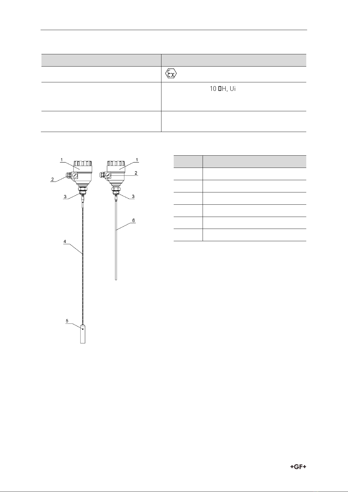
5Design and function............................................................................................................... 6
5.1 Function ................................................................................................................................. 6
5.2 Principle of operation............................................................................................................ 6
6Technical data........................................................................................................................ 7
6.1 Dimensions ............................................................................................................................ 8
7Installation ............................................................................................................................. 9
7.1 Handling and Storage............................................................................................................ 9
7.2 Mounting on the tank ...........................................................................................................10
7.2.1 Installation instructions: General notes..............................................................................10
7.2.2 Specific installation instructions: Gauge –solid applications ...........................................13
7.3 Wiring ....................................................................................................................................14
7.4 Power on and start-up .........................................................................................................17
8Programming type 2291.......................................................................................................18
8.1 The display unit.....................................................................................................................18
8.1.1 Behavior in manuals programming mode ..........................................................................18
8.1.2 Manual programming...........................................................................................................19
8.2 Characteristics .....................................................................................................................20
8.2.1 Gauge operating logic when the reflection is lost ..............................................................21
8.2.2 Gain and voltage amplitude..................................................................................................22
8.2.3 Typical signal trends ............................................................................................................24
8.2.4 Automatic adjustment..........................................................................................................25
8.2.5 Level measurement when more than one phase or layer in the tank ..............................25
9Troubleshooting....................................................................................................................27
10 Repair and Maintenance ......................................................................................................30
11 Accessories...........................................................................................................................30
12 Set-up parameters ...............................................................................................................30
13 Disposal.................................................................................................................................30

Instruction manual Intended use
5
1Intended use
The Level Transmitter uses the Time Domain Reflectometry (TDR) measuring principle and
two-wire technology for level measurement. It is designed for measuring the distance, level
and volume of liquids, pastes, slurries and powder products. The device is applicable in tank,
silo, rigid pipe, reaction vessel and level reference vessel.
The device is HART capable; it can be programmed using the GF Signet configuration
software Eview2 which is available on www.gfps.com/level
Please note: All display units also can be programmed directly without any additional
hardware.
2About this document
2.1 Warnings
This instruction manual contains warning notices that alert you to the possibility of injuries or
damage to property. Always read and pay attention to these warnings!
Danger of personal injury!
Failure to comply leads to a risk of personal injury!
Risk of damage to property!
Failure to comply leads to a risk of damage to property (loss of time, loss of data, device
fault etc.)!
3Safety and responsibility
Only use the product for the intended purpose, see Intended Use.
Do not use any damaged or faulty product. Sort out any damaged product immediately.
Have the product and accessories installed only by persons who have the required
training, knowledge or experience.
Regularly train personnel on all questions regarding the locally regulations applying to
occupational safety and environmental protection, especially for pressurize tanks.

Transport and storage Instruction manual
6
4Transport and storage
Protect the product against external forces during transport (impacts, knocks, vibrations
etc.).
Transport and / or store the product unopened in its original packaging.
Protect the product from dust, dirt, moisture as well as heat and ultraviolet radiation.
Ensure that the product is not damaged either by mechanical or thermal influences.
Before assembling, check the product for damage during transport.
5Design and function
5.1 Function
5.2 Principle of operation
The Type 2291 guided microwave level transmitter uses the TDR (Time Domain Reflectometry)
principle. The instrument sends low power ns wide pulses along an electrically conductive
rod, cable or coaxial probe with a known propagation speed (the speed of light). As the pulse
reaches the surface of the medium or phase of two liquids (altered dielectric constant r), a
part of it is reflected back to the electronic module. The efficiency of the reflected signal
depends on the dielectric constant r difference of the mediums or layers. (From the plain
surface of air-water phase the reflected signal's strength will be approx. 80% of the emitted
signal). The reflected pulse is detected as an electrical voltage signal and processed by the
electronics. Level distance is directly proportional to the flight time of the pulse. The
measured level data is converted into 4-20 mA current and HART signals and is displayed on
the LCD display. From the level data further derived measuring values can be calculated such
as volume and mass. The TDR technology is unaffected by the other properties of the medium
as well as that of the space above it.

Instruction manual Technical data
7
6Technical data
Data
Kv value
Input data
Measured values
Between the reference point of the unit and reflection
plane (material surface), distance, level, and volume
Measuring range
Single cable 6 m (19,7 ft), single rod 2 m (6.6 ft)
Housing
Plastic BPT
Medium temperature
–30 °C ... +90 °C (–22 °F ... +194 °F
Minimal dielectric constant (r)
1.9
Medium pressure
- 0.1 … 1.6 MPa (- 1… 16 bar) max. allowed pressure
at 20 °C (68 °F)
Ambient temperature
With display: –20 °C … +60 °C (-4 °F… +140 °F)
Sealing
FPM
Ingress protection
IP 65 (NEMA 4 –4X)
Power supply
18 … 35 V DC , nominal 24 V DC, Ex version 18 … 28V
Output
data
Output signals
Analogue: 4 … 20 mA, (3.9 … 20.5 mA) passive output,
error 22 mA
BUS: serial line, HARTinterface, terminal resistor max.
750 ohm
Display: LCD matrix
Accuracy
Liquids: 5mm. For probe
length L ≤10m 0.05% of the
range
Under ideal reflection
and stabilized
temperature conditions.
Resolution
3A
Electrical connection
2 x M20x1.5 metal cable glands Cable diameter: 7 … 13
mm (Ex), or M20x1.5 plastic cable glands, Cable
diameter: 6 … 12 mm
wire cross-section: 0.5 … 1.5 mm2(shielded cable is
advised) + 2 x NPT ½” for cable gland
Electrical protection
Class III.
Mass (housing)
1.5 kg

Technical data Instruction manual
8
Explosion Protection, Ex markings, Ex limit data
Type
Ex marking
II 1 D iaD A20/21 IP 65 T100°C
Intrinsically safe data
Ci ≤ 10 nF, Li ≤≤30 V, Ii ≤ 150 mA, Pi ≤
1 W For Ex transmitter only EEx ia power supply
should be used
Ex power supply
Uo < 30 V, Io < 150 mA, Po < 1 W, Supply range 18
V … 30 V
6.1 Dimensions
Nr.
Description
1
Housing
2
Cable gland
3
Process connection
4
Mono cable probe
5
Weight
6
Mono rod probe

Instruction manual Installation
9
7Installation
7.1 Handling and Storage
The device will weigh between approximately 1.5 kg or 3 lb, 12 kg or 25 lb.
Carry using both hands to lift the device carefully by the converter housing. If necessary, use
lifting gear. No attempt should be made to lift the instrument by its probe. Caution: The
probe is a critical gauge component. Do not damage - Handle with care!
Avoiding blows - avoid hard blows, jolts, impacts, etc. Caution: fragile electronics
Avoid bending (single rod and coaxial
probes) - Support the probe to avoid
bending.
400mm
minimum
+80°C
-40°C
Avoid cable kinks and fraying
Do not coil the cable less than 400 mm or 16 “
in diameter. Cable kinks or fraying will cause
measurement errors.
Storage temperature

Installation Instruction manual
10
7.2 Mounting on the tank
7.2.1 Installation instructions: General notes
Prior the installation some consideration is to be made regarding tank fittings and tank shape.
Nozzle position in relation to the tank walls and other objects inside the tanks
(Warning: this free area will depend on the probe type selected: refer to later on in this
section) type of tank roof, i.e. floating, concrete, integral, etc; and base, i.e. conical, etc.
Whenever working on an installation, remember to: Disconnect the power supply before
starting work. However, the gauge may be installed when the tank contains product.
Threaded process connections
The simplest and most economical way is to
mount type 2291 directly on the tank with the
1” BSP or 1” NPT threaded connection.
Nozzle height
Do not fit a nozzle longer than its diameter,
especially for single probes and powder
applications.
h ≤Ød
h = nozzle height and
d = nozzle diameter
Nozzles penetrating into tank
Caution: Do not use nozzles that penetrate
into the tank. This will disturb the emitted
pulse.

Instruction manual Installation
11
Installation of two devices
If two devices are to be used on the same
tank, these should be mounted at a distance
of at least 2 m or 6.5 ft away from each other.
If not, interferences from the electromagnetic
(EM) fields generated by both instruments
may cause measurement errors.
Coaxial probes: the outer shell of the probe
contains the EM field: no minimum distance
required.
Process connection and entry pipe
Caution: Do not put the nozzle close to the
entry pipe.
Pouring the product directly onto the probe
will give false readings.
Install deflector plate if impossible to
distance gauge from entry pipe.
Install far from
entry pipe
or use a
deflector
plate
medium
Stilling wells
Tanks with floating roofs for petrochemical
applications: Use a stilling well.
1 Stilling well
2 Tank
3 Floating roof
4 Product (petroleum applications)
5 Well fixed to tank base (no roof deformation)
6 Sediment

Installation Instruction manual
12
Probes: entanglement, straightness and tank
bottom clearance
Cable probes must be straight once inserted
into the tank.
They must also be far from other objects (e.g.
mixers) to avoid entanglement.
In order to maintain the gauge’s operating
characteristics, it is recommended to avoid
touching the tank bottom with the
counterweights (for cable probes) or probe
end (other types).
Avoid mounting near objects (discontinuities)
inside the tank that influence the probe’s EM
(electromagnetic) field
Install the gauge far from protruding objects
such as: heating tubes, sudden changes in
tank cross-section, tank wall reinforcements
and beams, weld lines and dip-stick pipes,
etc.
1. Agitator
2. Support beam perpendicular to the pulse
direction
3. Abrupt changes in tank cross section
4. Heating tubes
5. Alternative solution: reference chamber
- electromagnetic field is within chamber
6. Gauge electromagnetic field:
Any intruding metallic object will be
detected in this zone if perpendicular to
the emitted pulse direction.
Do not fit the gauge near to these objects.
When measuring liquids the use of a stilling
well or reference chamber is favorable
because it ensures electromagnetic
protection for an accurate measuring.
Use a sunshade if the unit is exposed to
direct sunlight.
No electromagnetic field outside the
reference chamber.

Instruction manual Installation
13
Fastening the probe to the tank bottom
Flexible probes can be fastened with a chuck (ring), turnbuckle or similar fastening device to
the tank bottom.
Shortening cable probes
If required, the cable probe can be shortened, but this applies only when used in liquids.
Procedure
1. Detach socket set screw M6x10 (ISO 4026)
with 5 mm Allen (hexagon) key (ISO 2936).
2. Pull cable out of counterweight and
shorten to required length using cable
cutters to prevent the cable wires and
strands from splaying out.
3. Insert cable back into counterweight and
tighten down screws
4. Change configuration parameters to new
probe length; the reference point is the
top edge of the weight.
7.2.2 Specific installation instructions: Gauge –solid applications
False readings
1. Do not let the probe touch the side of the
nozzle.

Installation Instruction manual
14
Conical silo nozzles, false readings and
traction on the cable probes
2. High traction forces:
We recommend that the probe should not
be anchored to avoid excessive traction
loads on the cable.
3. Bending and traction:
Position the connection on the roof at ½
radiuses of the tank and with minimum
nozzle height. This will avoid damage due
to bending and traction during emptying.
Product build-up can occur under the nozzle:
this may weaken the pulse.
Avoid cavities that permit the build-up of
deposits.
7.3 Wiring
Wiring in non-Ex environment Wiring in non-Ex environment
No.
Description
1
Detach the cover of the unit
2
Guide the cable into the housing
through the cable gland
3
Remove a 4 mm length of isolation
from the wires and cut away the free
part of the shielding
4
Connect the wires of the current loop
to terminals 2 and 3 (any polarity).
5
Pull back the cable till a 10 mm cable
length remains in the housing behind
the cable gland.
Tighten the cable gland using two
spanners.
Check the connection of wires and the
tightness at the cable gland
6
Array the wires in the housing and
screw the cover on the housing.
The 500V AC insulation test should not
be performed on the instrument
because of the overvoltage protection
of the electronics.

Instruction manual Installation
15
Connection to the EP network (grounding).
Screw type terminal (EP) on the housing max. cable cross-section: 4 mm².
The housing of the Type 2291 must be grounded.
Grounding resistance R < 1 Ohm
The shielding of the signal cable should be grounded at the control room.
Avoid coupling of electromagnetic noises place the singnal cable away from power-current
cables.
Electrostatic discharge (E.S.D.)
Type 2291 non-Ex and Ex gauge electronics
are shielded up to 4 kV against E.S.D.
Note: E.S.D. cannot be solved by Type 2291
E.S.D. protection.
It is the customer’s responsibility to avoid
E.S.D. by grounding the tank, product and
probe installation.
1. Danger of injury
The probe may receive an electrostatic
discharge during operation; earth the
probe by pushing it against tank wall with
a suitably isolated tool just before
touching it to avoid receiving a shock.
2. Earth the entry pipe and product.

Installation Instruction manual
16
Non-hazardous-duty version
=
US
RA
HART
4 ... 20mA
UE
MikroTREK 2-wire
mA
L
Power supply
Nominal voltage
24 V DC
Maximum voltage (Uinput):
35 V DC
Minimum voltage (Uinput):
dependent on load impedance, see graph
below
Load impedance RA
Loop resistance, Rloop
RHART + Rcable + Rammeter Ohm
Minimum load impedance RA
0 Ohm
Maximum load impedance RA
750 Ohm
RHART resistance for HART® communication
250 Ohm, recommended
Line A = minimum voltage at the Type 2291 wire terminals
Line B = minimum supply voltage (for voltage drop caused by a 250 Ohm loop resistance)
Example for calculating the power supply: The voltage drop is tested at 22 mA:
U power minimum 22 = 22 mA x load impedance + Uinput minimum 22
U power minimum 22 = 22 mA x 250 Ohm + 10 V = 5.5 V + 10 V = 15.5 V
2291 2-wire

Instruction manual Installation
17
In order to cover the whole current range, the voltage drop must also be tested at 4 mA:
By analogy, the following applies:
U power minimum 4 = 4 mA x load impedance + Uinput minimum 4
U power minimum 4 = 4 mA x 250 Ohm + 18 V = 1 V + 18 V = 19 V
At a load impedance of 250 Ohm a power supply voltage of 19 V is sufficient to energize the
current device range of 4 to 20 mA.
Hazardous-duty version
Connect the wires of the current loop to terminals 2 and 3 (any polarity).
The intrinsically safe certified device may only be used in conjunction with an other
intrinsically safe certified equipment.
All the allowed electrical safety data indicated on the nameplate must be observed.
An ’Ex’ repeater power supply unit must be
used
For calculation of the supply voltage the same
applies as for the standard non-’Ex’ version.
The connected Ex repeater must be HART®-
compatible so that it can be operated with the
GF Signet Eview 2 communication software.
The HART adapter should be connected to the
intrinsically safe input of the Ex repeater!
The units with plastic coating can only be
used in IIB gas class hazardous area.
RA
=
non areaEx Ex area
HA RT
Mi roTREK 2c -wire
mA
L
[Ex ia] 4-20mA
EEx ia
7.4 Power on and start-up
The Type 2291 wire is pre-configured in accordance to customer order specifications and
measurements can be made immediately. A start-up time of less than 60 seconds should be
allowed once the unit is connected and the power is switched on.
If the probe length has been shortened since delivery, please refer to section.
2291 2-wire

Programming type 2291 Instruction manual
18
8Programming type 2291
The main parameters of the Type 2291 can be also set using the display unit.
The default display shows the primary measured value (which the output current is calculated
from).Besides the numerical display there is a bargraph on the right showing the value of the
current output.
Programming is helped by a text-based menu. Navigation in the menu can be done with
E
/
/ / buttons.
8.1 The display unit
The display unit is a 64x128 dot-matrix LCD display which can be plugged into the transmitter.
The display based on LCD technology, do not expose to continuous
direct sunlight to avoid display damage.
If type 2291 is not equipped with a sunshade and ambient
temperature exceeds the operating temperature of LCD do not leave
the LCD in the instrument!
Display
64x128 Dot-matrix LCD, glyphs, units and bargraph
Ambient temperature
–20°C…+60°C
Housing material
PBT fiberglass, plastic (DuPont)
8.1.1 Behavior in manuals programming mode
After power-up Type 2291 shows the measured value on the LCD.
Remote mode:
If the instrument senses external HART communication it changes its display mode and
shows a "REMOTE MODE" message in the bottom of the display. In this mode the measured
values are refreshed according to the queries of the external HART master.
If the HART master does not refresh the display will show the last measured values.
In the absence of display unit the COM LED indicates the HART communication.
If HART communication stops the COM LED turns off after 120 sec.
Entering the menu can be done by pressing the
E
button. Scrolling the menu can be done by
pressing and buttons.
Enter into selected menu point with
E
button. Exit to the previous menu with button.
The buttons work only in presence of display unit.
When leaving the Type 2291 in (programming) menu after 30 minutes the instrument
automatically returns to measuring mode.
If display unit is removed the instrument instantly returns to measuring mode.

Instruction manual Programming type 2291
19
Because manual programming (with display unit) and remote programming (with external
HART master, or GF Signet Eview 2 software) cannot be performed at the same time (as both
of them act like a HART master) only one programming mode has priority and this is manual
programming.
During manual programming the instrument sends the "BUSY" response to the external
HART master device. (HART response code 32 - Device is busy)
8.1.2 Manual programming
Manu structure
Main menu
BASIC SETUP
OUTPUT SETUP
APPLICATION
Sub-menu
TANK HEIGHT
CURRENT MODE
APPLICATION TYPE
DEAD ZONE
FAILURE CURRENT
CLOSE-END BLOCKING
CURRENT MIN
DAMPING TIME
CURRENT MAX
PROBE LENGTH
ERROR DELAY
Changing parameters can be done by selecting a sub-menu and pressing
E
button in two
ways:
Text-based list:
Navigation is the same as in menu lists.
Accept changes with
E
button, cancel changes (and exit) with button.
Numerical field:
Serves for editing a numeric value.
Editing is helped by a cursor (inverted character).
Change the value of the selected digit with / buttons
(There is no under-, and overflow between the characters).
Selecting a digit can be done using the button.
Accept changes with
E
button.
After accepting the parameter change the Type 2291 checks the parameter and
downloads it.
If parameter is incorrect the CHECK/WRITE FAILED! message appears.

Programming type 2291 Instruction manual
20
8.2 Characteristics
This subsection explains:
the four principle configurations for setting up a measurement scale and what the user
should be aware of in each case;
what happens when the tank is full or empty;
what is the level threshold and how to modify it
what happens when level is measured when more than one product in the tank;
The measurement scale:
Five possible configurations for analogue current output –with “Level” selected in the EView
2 configuration software.
Nr.
Description
A
Tank height
B
Probe length
C
Detection delay
D
Non-measurable zone
E
Minimum distance between
non-measurable zone and
dead zone
F
Upper dead zone
G
Measuring range
H
Reference point at tank
bottom
The configurations described below are illustrated in the above diagram
1. The “current output” range is smaller than the max. possible measuring range
2. The “current output” range is equal to the measuring range:
Scale min.: 4 mA = tank height –probe length + H
Scale max.: 20 mA = tank height –dead zone
3. The “current output” range is greater than the measuring range:
Scale min.: 4 mA = 0.0
Scale max.: 20 mA = tank height –dead zone
4. The “current output” range is greater than the measuring range:
Scale min.: 4 mA = tank height –probe length + H
Scale max.: 20 mA = tank height
Table of contents
Other GF Transmitter manuals
Popular Transmitter manuals by other brands

Transmitter Solutions
Transmitter Solutions Firefly3 FIRlll433TSD22K3 manual

Sennheiser
Sennheiser TVC2-TX quick guide

Xantech
Xantech HDTXSG01 installation instructions

Dwyer Instruments
Dwyer Instruments 608 Series Specifications-installation and operating instructions

DLO
DLO TransDock micro user manual

Evikon
Evikon PluraSens E2638-Cl2 user manual