Signet
Conductivity/Resistivity
Transmitter
ENTER
62.50 uS/cm
25.0 C
Signet 8850-2 Conductivity/Resistivity Transmitter
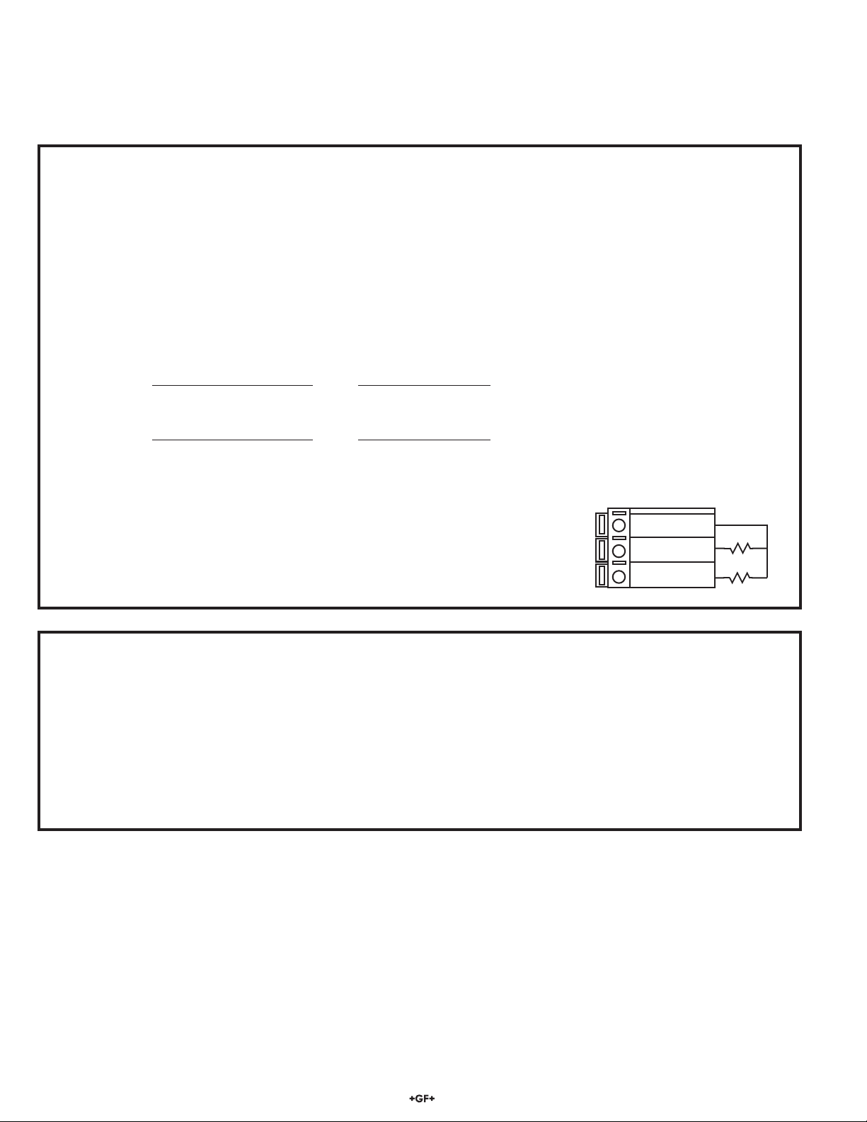
2. Specifications
General
Compatible electrodes: Signet 3-28XX-1 Standard and Certified
(NIST) Series Conductivity/Resistivity Electrodes
Accuracy: ±2% of reading
Enclosure:
• Case: PBT
• Panel gasket: Neoprene
• Window: Polyurethane coated polycarbonate
• Keypad: Sealed 4-key silicone rubber
• Weight: Approx. 325 g (12 oz.)
Display:
• Type: Alphanumeric 2 x 16 LCD
• Contrast: User selected, 5 levels
• Update rate: 1.8 s
Electrical
Power: 12 to 24 VDC ±10%, regulated, 290 mA max.
Sensor input range:
• Conductivity: 0.01 μS/cm to 400 000 μS/cm
• Resistivity: 10 KΩ/cm to 100 MΩ/cm
• TDS: 0.023 to 200 000 PPM nominal
(adjustable μS/PPM)
• Temperature: PT 1000, -25 to 120 °C (-13 to 248 °F)
Measurements above 10 MΩ(below 0.1 μS) must be
performed in solution temperatures from 20 to 100 °C.
4 to 20 mA Outputs:
• Passive, isolated, fully adjustable and reversible 4 to 20 mA
outputs are independently source selectable for conductivity or
temperature.
• Max loop impedance: 50 Ωmax. @ 12 V
325 Ωmax. @ 18 V
600 Ωmax. @ 24 V
• Update rate: 200 ms
• Accuracy: ±0.03 mA @ 25 °C, 24 V
Relay outputs (2 sets mechanical SPDT contacts):
• Max. voltage rating: 5 A @ 30 VDC or
5 A @ 250 VAC, resistive load
• Hi or Lo programmable with adjustable hysteresis
• Pulse programmable (maximum 400 pulses/minute)
Environmental
• Operating temperature: -10 to 70 °C (14 to 158 °F)
• Storage temperature: -15 to 80 °C (5 to 176 °F)
• Relative humidity: 0 to 95%, non-condensing
• Maximum altitude: 2000 m (6562 ft)
• Rating: NEMA 4X/IP65 front
• Insulation category: II
• Pollution degree: 2
Standards and Approvals
• CE, UL, CUL listed
• RoHS compliant
• Manufactured under ISO 9001 and ISO 14001
CAUTION!
• Remove power to unit before wiring input
and output connections.
• Follow instructions carefully to avoid
personal injury.
Contents
1. Installation
2. Specifications
3. Electrical Connections
4. Menu Functions
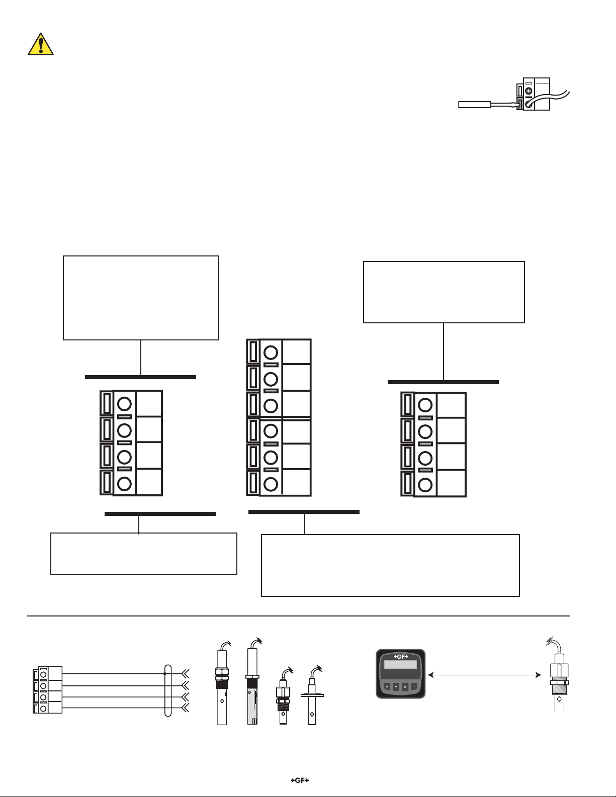
1. Installation
ProcessPro transmitters are available in two styles: panel mount and field mount. The panel mount is supplied with the necessary
hardware to install the transmitter. This manual includes complete panel mounting instructions.
Field mounting requires a separate mounting kit. The 3-8050 Universal kit (159 000 184) enables the transmitter to be installed
virtually anywhere. Detailed instructions for field installation options are included with the 3-8050 Universal kit.
1.1 Panel Installation
1. The panel mount transmitter is designed for installation using a 1/4 DIN punch. For manual panel cutout, an adhesive template
is provided as an installation guide. Recommended clearance on all sides between instruments is 1 inch.
2. Place gasket on instrument, and install in panel.
3. Slide mounting bracket over back of instrument until quick-clips snap into latches on side of instrument.
4. To remove, secure instrument temporarily with tape from front or grip from rear of instrument. DO NOT RELEASE.
Press quick-clips outward and remove.
Output -
Output +
System Pwr
Loop -
System Pwr
Loop +
2
14
3
Sensr Gnd
(SHIELD)
Sensr IN
(RED)
Sensr V+
(BLACK)
7
6
5
8050
106 mm (4.2 in.)
42 mm
(1.7 in.) 64 mm
(2.5 in.)
92 mm
(3.6 in.)
97 mm
(3.8 in.)
56 mm
(2.2 in.)
41 mm
(1.6 in.
)
Optional
Rear
Cover
96 mm
(3.8 in.)
96 mm
(3.8 in.)
quick-clips
gasket panel
terminals mounting
bracket
latch
Panel Mount
Installation Detail
82 mm
(3.23 in.)
SIDE VIEW
Field Mount Panel Mount
SIDE VIEW
FRONT VIEW
Field Mount &
Panel Mount
3-8850.090-2 Rev. J 4/12 English
*3-8850.090-2*
English
Chinese RoHS (Go to www.gfsignet.com for details)