1Signet 8250-2 Level Transmitter
CAUTION!
• Remove power to unit before wiring
input and output connections.
• Follow instructions carefully to avoid
personal injury.
Signet 8250-2 Level Transmitter English
Contents
1. Description
2. Specifications
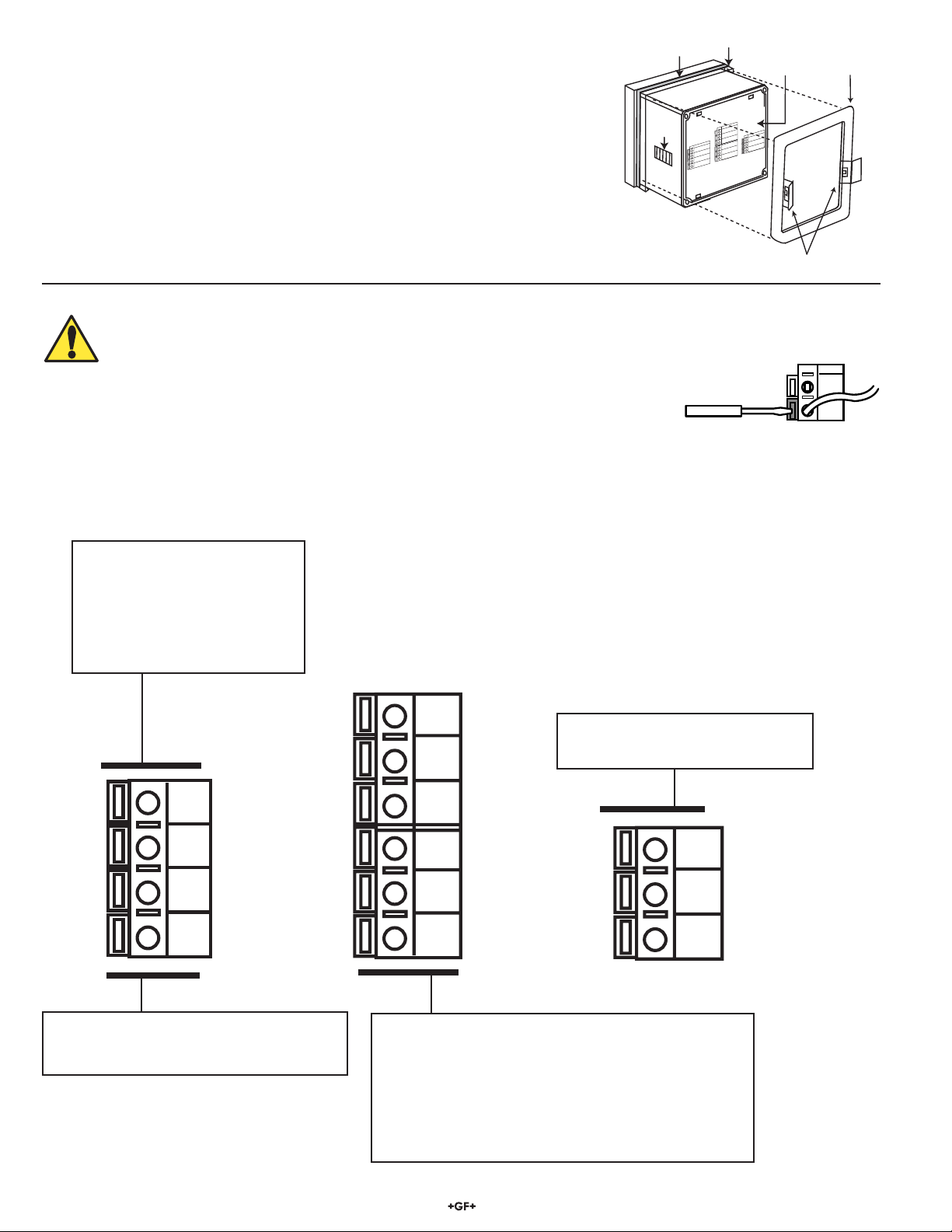
3. Panel installation
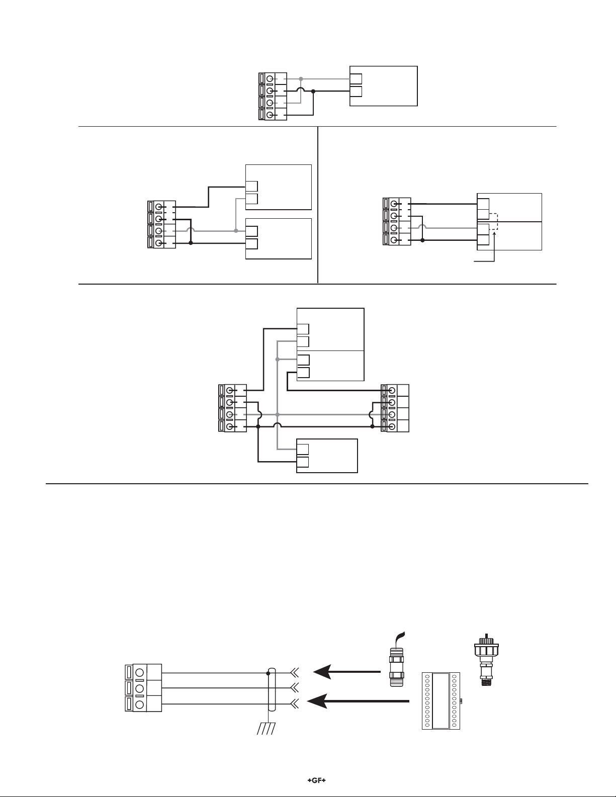
4. Electrical Connections
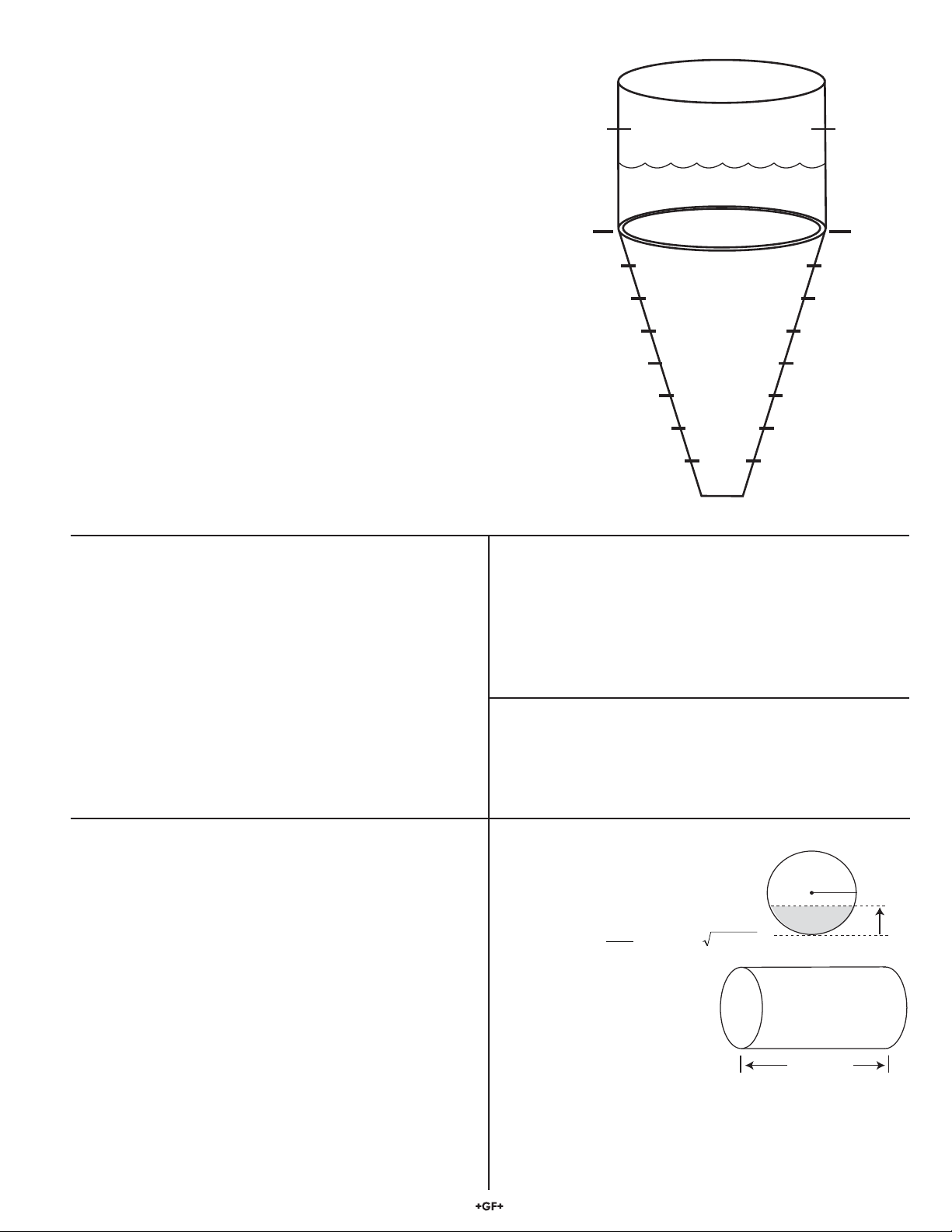
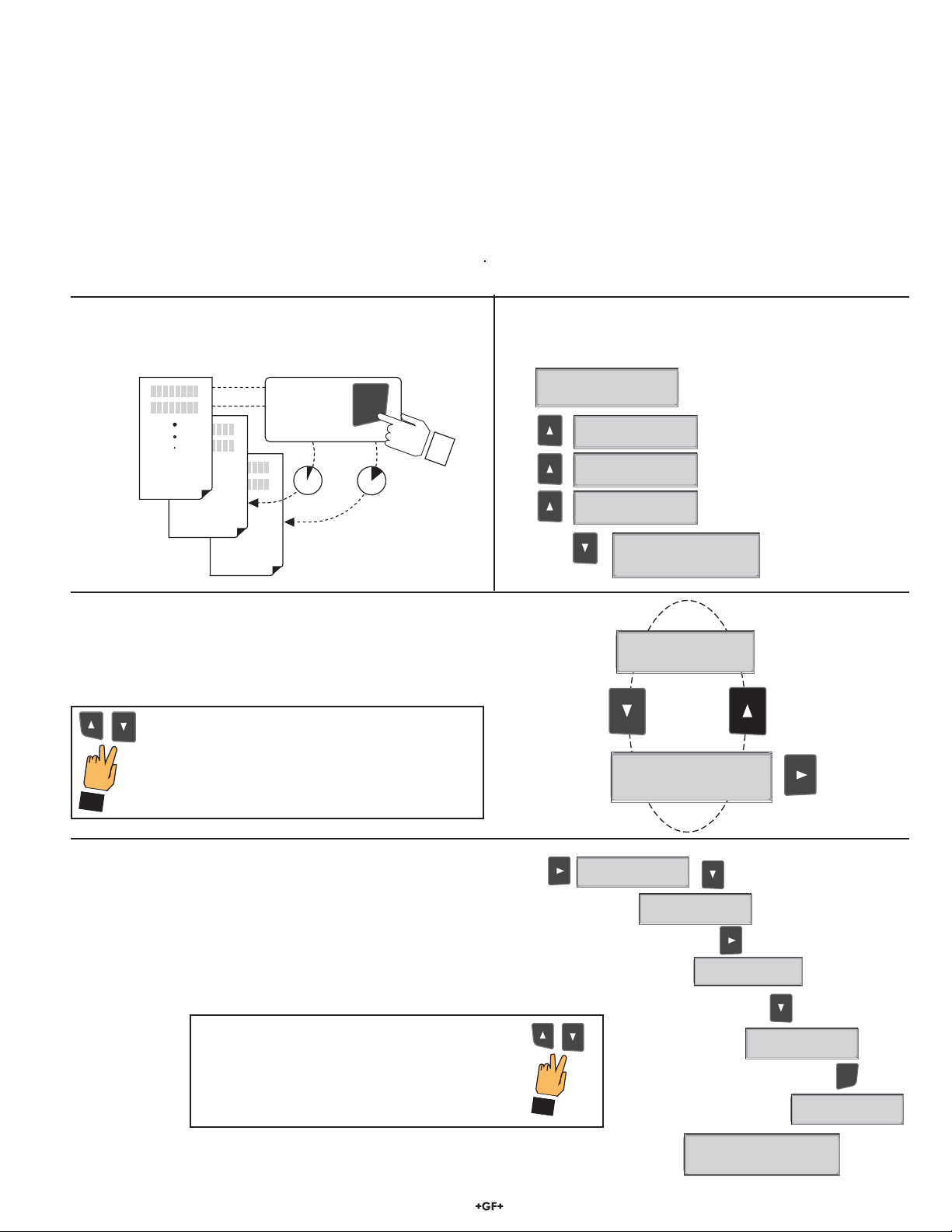
5. System configuration
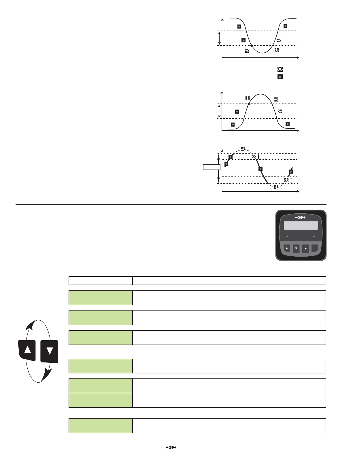
Signet Level
Transmitter
Level
+10.00 ft
Relay 1 Relay 2
ENTER
1. Description
ProcessPro transmitters are available in two styles: panel mount and field mount. The panel mount is supplied with the necessary
hardware to install the transmitter. This manual includes complete panel mounting instructions.
Field mounting requires one of two separate mounting kits. The 3-8052 integral kit joins sensor and instrument together into a single
package. The 3-8050 Universal kit enables the transmitter to be installed virtually anywhere.
Detailed instructions for integral mounting or other field installation options are included with the 3-8052 Integral kit or the 3-8050
Universal kit.
General
Compatible Sensors: Signet 2450 Pressure Sensor (S3L)
Signet 2250 Level Sensor (S3L)
Other 3rd party sensors with 4 to 20 mA
output (via Model 8058)
Materials:
• Case: PBT
• Panel case gasket: Neoprene
• Window: Polyurethane-coated polycarbonate
• Keypad: Sealed silicone rubber, 4-button
Weight: Approx. 325 g (12 oz.)
Display:
• Alphanumeric 2 x 16 LCD
• Display update rate: 1 second
• Contrast: User selected, 5 levels
Electrical
Power supply: 12-24 VDC ±10% regulated,
250 mA max current
Sensor power: 5 VDC ±1% @ 25 ºC, regulated
2-wire system: 1.5 mA maximum current
4-wire system: 20 mA maximum current
Current output:
• 4 to 20 mA, isolated, fully adjustable and reversible
• Max loop impedance: 50 Ωmax. @ 12 V
325 Ωmax. @ 18 V
600 Ωmax. @ 24 V
• Update rate: 300 ms
• Output accuracy: ±0.03 mA
Relay outputs (2 sets mechanical SPDT contacts):
• Software supports 2 additional relays via optional external relay module
Note: When using the 8059-4 or -4AC, only relays 1 and 2 can be
utilized with the level instrument.
• Maximum voltage rating:
5 A @ 30 VDC, or 5 A @ 250 VAC, resistive load
• Programmable for High or Low setpoint or for Window range,
with adjustable hysteresis
• May be disabled if not used
• Time delay: Programmable from 0 s to 6400 s
Environmental:
• Operating temperature: -10 °C to 70 °C (14 °F to 158 °F)
• Storage temperature: -15 °C to 80 °C (5 °F to 176 °F)
• Relative humidity: 0 to 95%, non-condensing
• Maximum altitude: 2000 m (6562 ft)
• Enclosure: NEMA 4X/IP65 front
Standards and Approvals:
• CE, UL listed
• Immunity: EN50082-2
• Emissions: EN55011
• Safety: EN61010
• Manufactured under ISO 9001 for Quality, ISO 14001 for
Environmental Management and OHSAS 18001 for
Occupational Health and Safety.
China RoHS (Go to www.gfsignet.com for details)
Declaration of Conformity according to FCC Part 15
This device complies with Part 15 of the FCC rules.
Operation is subject to the following two conditions:
(1) This device may not cause harmful interference, and,
(2) This device must accept any interference received, including
interference that may cause undesired operation.
2. Specifications
Dimensions
3-8250.090-2 Rev. H 01/13 English
3-8250.090-2
6. View menu
7. Editing procedure
8. Calibrate menu
9. Options menu
10. Troubleshooting
92 mm
(3.6 in.)
97 mm
(3.8 in.)
56 mm
(2.2 in.)
41 mm
(1.6 in.)
Optional
Rear
Cover
96 mm
(3.8 in.)
96 mm
(3.8 in.)
106 mm
(4.18 in.)
82 mm
(3.23 in.)
SIDE VIEW
Field Mount w/
8052 Integral kit
107 mm
(4.2 in.)
96 mm
(3.8 in.)
Panel Mount
SIDE VIEW
FRONT VIEW
Field Mount &
Panel Mount
SIDE VIEW
Field Mount w/
8050 Universal base