page 1 of 8
8350-3 Temperature Transmitter Instructions
CAUTION!
• Remove power to unit before wiring
input and output connections.
• Fo ow instructions carefu y to avoid
persona injury.
+GF+ SIGNET 8350-3 Temperature Transmitter Instructions ENG ISH
Contents
1. Insta ation
2. Specifications
3. E ectrica Connections
4. Menu Functions
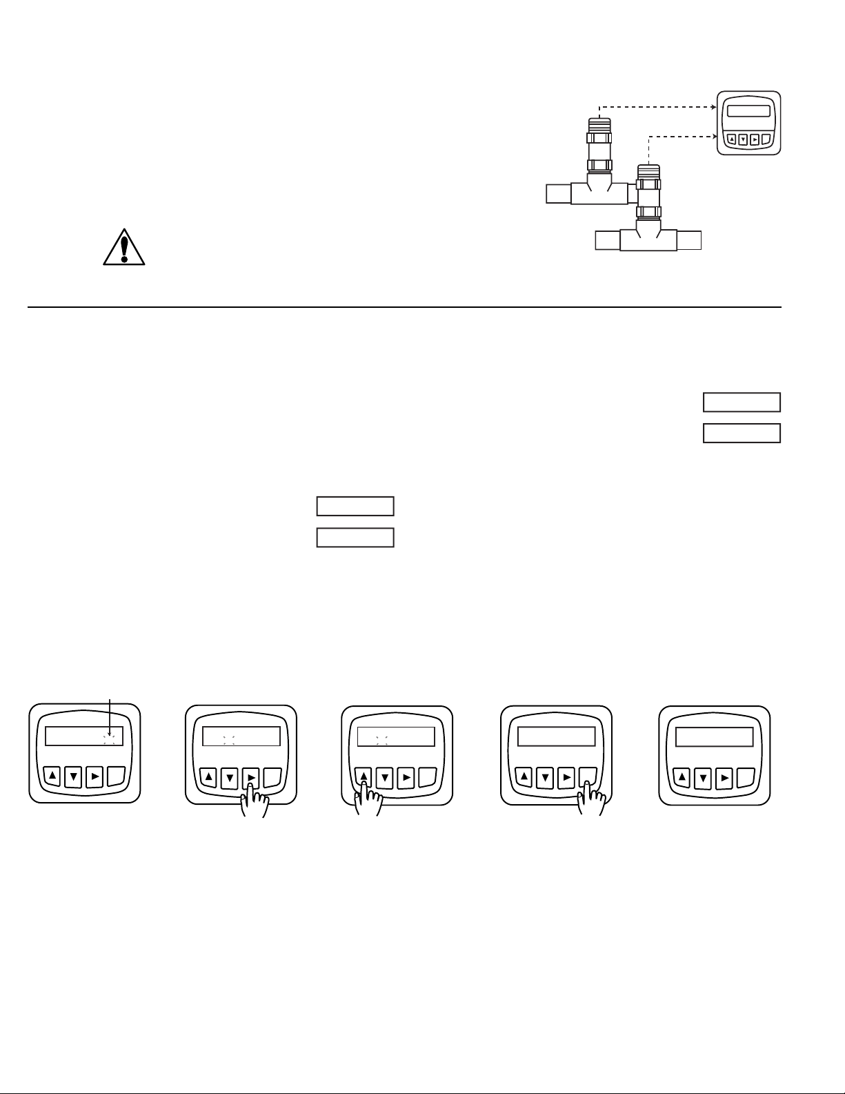
Temperature
Temp Units:
°C °F
Relay 1 Relay 2
ENTER
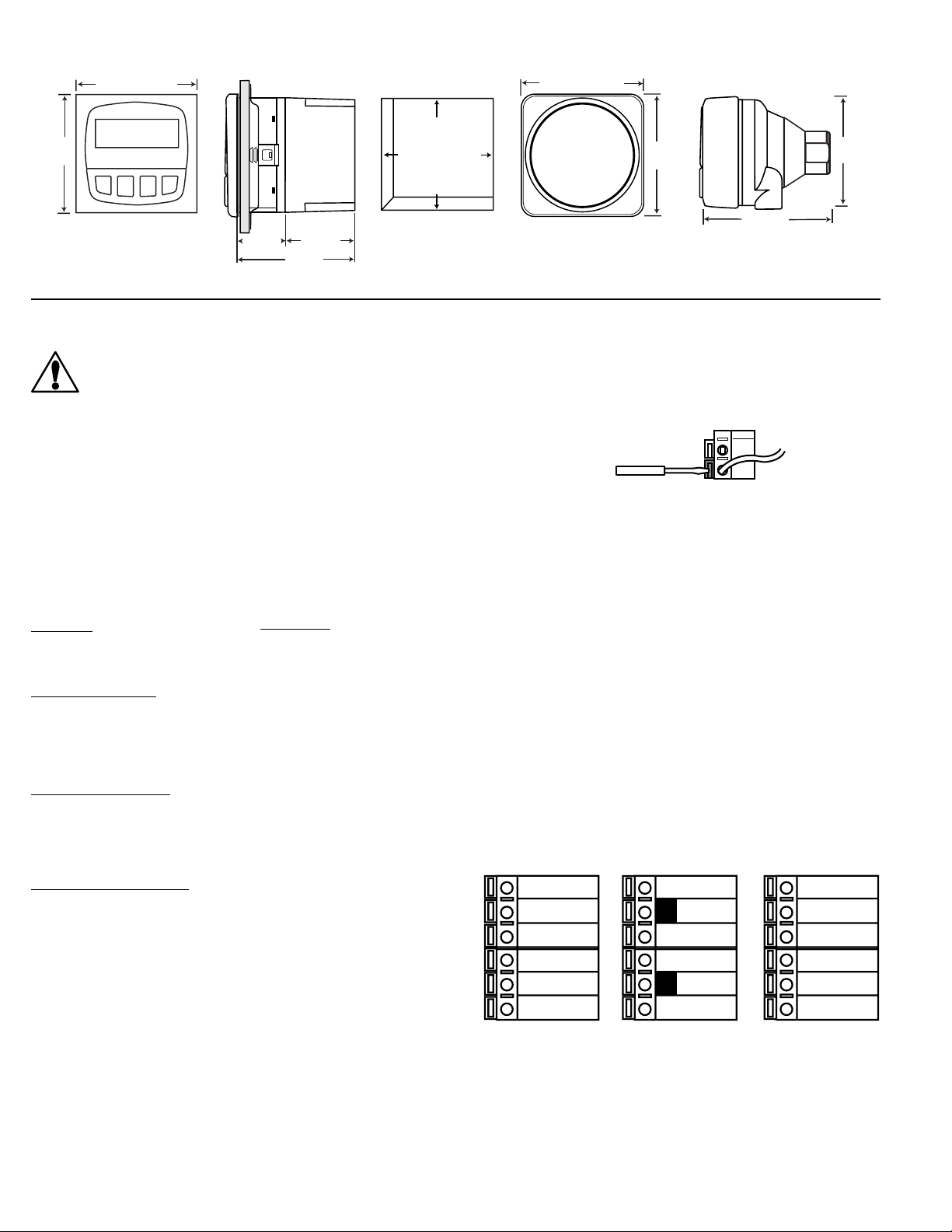
1.1 Panel Installation
The Pane Mounting kits are supp ied with the hardware to
insta instrumentation into pane s and maintain a NEMA 4X
watertight sea .
1. Punch out pane and de-burr edges. Recommended
c earance on a sides between instruments is 1 inch.
2. P ace gasket on instrument, and insta in pane .
3. S ide mounting bracket over back of instrument unti
quick-c ips snap into atches on side of instrument.
4. Connect wires to termina s.
5. To remove, secure instrument temporari y with tape from
front or grip from rear of instrument. DO NOT RELEASE.
Press quick-c ips outward and remove.
1.2 Integral Assembly (3-8052)
1. Punch out conduit ports if necessary.
2. Connect sensor to integra adapter. Push and twist- ock
integra adapter to conduit base and secure with ocking
ring and screw.
3. Mount unit in pipe. Route cab e through cab e g and and
connect to transmitter.
4. C ose unit and secure. Sea cab e entry.
1.3 Universal Assembly (3-8050)
1. Insta transmitter base
2. Connect wires to transmitter.
3. C ose unit and secure with push and twist ock.
Sea cab e entry.
1. Installation
The transmitter is avai ab e in three versions: a pane mount version, an integra (pipe mount) version, and a universa assemb y for
insta ation near the sensor.
Standards and Approvals
• CSA, CE, UL isted
• Manufactured under ISO 9001
Electrical
Sensor Input: Range: -10 to 100°C
Current outputs (2):
• 4 to 20 mA, iso ated, fu y adjustab e and reversib e
• Power: 12 to 24 VDC ±10%, regu ated, 60 mA max current
• Max oop impedance: 50 Ω max. @ 12 V, 325 Ω max. @ 18 V
600 Ω max. @ 24V
• Update rate: 200 ms
• Accuracy: ±0.03 mA
Open-co ector outputs (2 each): Hi, Lo, Pu se Programmab e
• Open-co ector, iso ated, 50 mA sink or source, 30 VDC max.
pu -up vo tage
• Hysteresis: User adjustab e
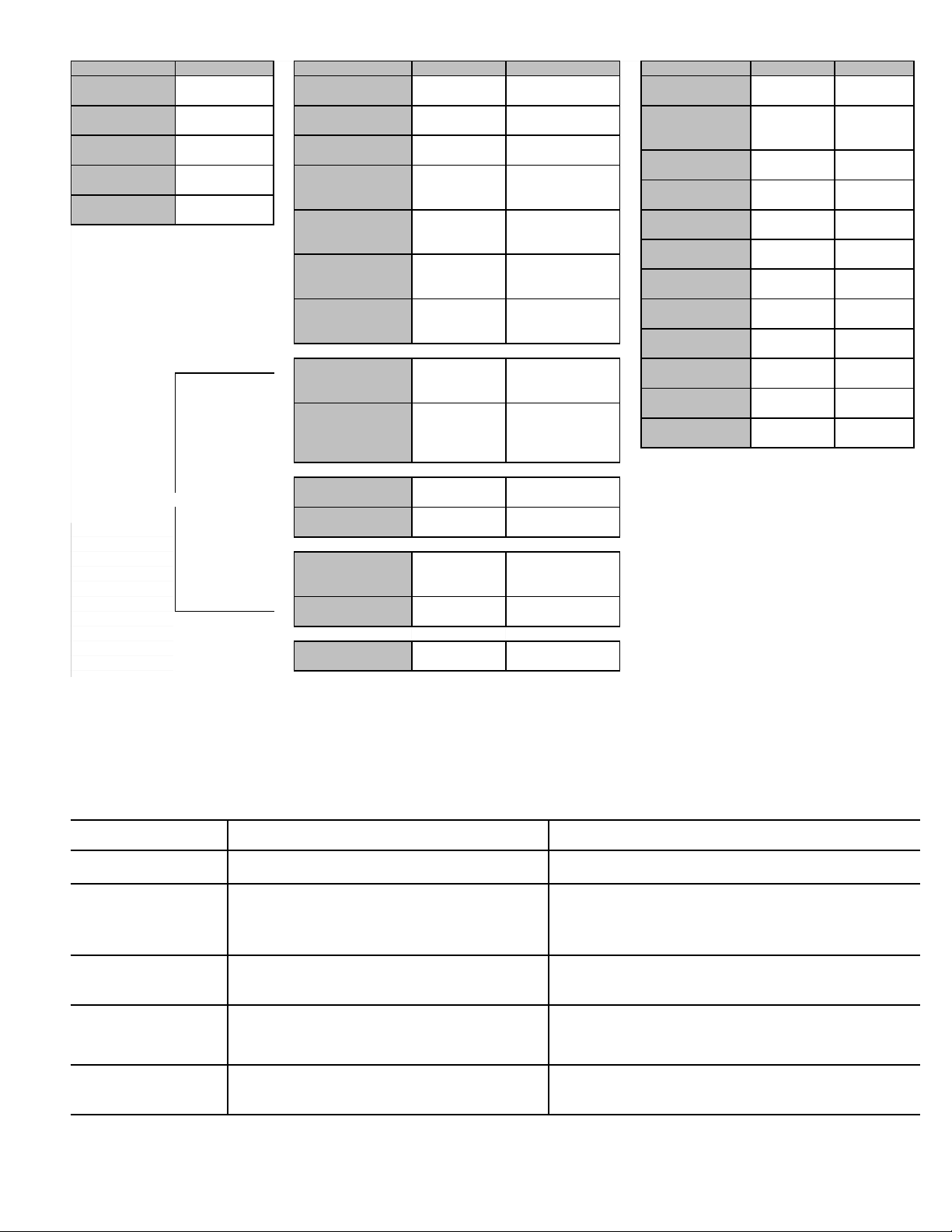
2 . Specifications
General
Compatibi ity: +GF+ SIGNET 3-2350-1 or -2 Temperature
Sensors
Accuracy: ±0.5° C
Enc osure:
• Rating: NEMA 4X/IP65 front
• Case: PBT
• Window: Po yurethane coated po ycarbonate
• Keypad: Sea ed 4-key si icone rubber
• Weight: Approx. 325g (12 oz.)
Disp ay:
• A phanumeric 2 x 16 LCD
• Update rate: 1 second
• Contrast: User se ected, 5 eve s
Environmental
Operating temperature: -10 to 70°C (14 to 158°F)
Storage temperature: -15 to 80°C (5 to 176°F)
Re ative humidity: 0 to 95%, non-condensing
1
8
7
Interna open-co ector
output circuit Outputs
Iso ation
15Ω
S
D
2
10
9
_
+
sea
sea
wires
quick-c ip
gasket pane
termina s
mounting
bracket
atch
transmitter
Liquid Tight
Connector
(cab e g and)
B-1/00 Eng ish
3-8350.090-3