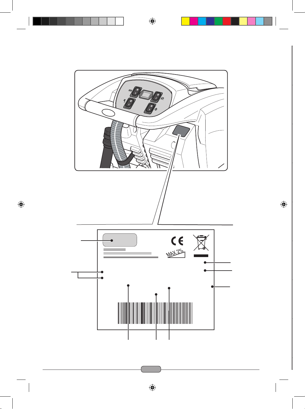
Ghibli ROUND 45 E 55 TOUCH User guide

ROUND 45 E 55 TOUCH
ROUND 45 E 55 TOUCH
IT
Uso e Manutenzione
EN
Use and Maintenance
FR
Utilisation et Entretien
DE
Gebrauch und wartung
ES
Uso y Mantenimiento
PT
Uso e manutenção
NL
Gebruik en Onderhoud
NO
Bruk og vedlikehold
DK
Brug og vedligeholdelse
SV
Användning och underhåll

0 - 2
Year: ........
Art.: ...............
Mod: .......................Scrubber Dryer
....... - ....... V
..... W ..../.... Hz
Nr. .............................. IPX4 GVW ......... Kg
MADE IN ITALY
....................................
1
8
5
7
2
3 46
1 2 3 4 5 6 7 8
IT
Produttore Caratteristiche elettriche N° Matricola Grado di protezione Peso in ordine di marcia Anno di costruzione Codice articolo Modello
EN
Manufacturer Electrical characteristics Serial N° Degree of protection Weight in running order Year of manufacture Item code Model
FR
Producteur Caractéristiques électriques N° Matricule Degré de protection Poids en ordre de marche Année de construction Référence de l’article Modèle
DE
Hersteller Elektrische Eigenschaften Matrikelnr. Schutzgrad Gewicht bei Betrieb Baujahr Artikelnummer Modell
ES
Fabricante Características eléctricas N° Matrícola Grado de protección Peso en orden de marcha Año de fabricación Código del artículo Modelo
PT
Produtor Características elétricas Número de série Grau de protecção Peso em ordem de marcha Ano de construção Código do artigo Modelo
NL
Producent Elektrische eigenschappen Serienummer Beschermingsgraad Gewicht in rijklare toestand Bouwjaar Artikelcode Model
NO
Produsent Elektriske egenskaper Matrikkelnr. Grad av beskyttelse Vekt i kjøreklar stand Byggeår Artikkelnummer Modell
DK
Fabrikant El-specifikationer Matrikelnummer Tæthedsgrad Vægt i køreklar stand Byggeår Artikelkode Model
SV
Tillverkare Elektriska egenskaper Serienummer Grad av skydd Vikt i körklart skick Byggnadsår Artikelnummer Modell

EN
EN-1
Dear Customer,
Thank you for choosing one of our cleaning products.
The floor scrubber dryer that you have purchased has been designed to satisfy the user
in terms of ease of use and reliability over time.
We are aware that in order for a good product to stay that way, over time, it requires
continuous updates aimed at meeting the expectations of those who use it on a daily
basis. For this reason, we hope that you will not only be a satisfied customer but also a
partner who does not hesitate to give us your opinions and ideas originating from your
personal day-to-day experience.

EN
EN-2
Technical data
Index
* The washing width is intended with the machine operating and the brush pressed down.
Type of use Operator on ground
Characteristics
Power supply voltage See technical data plate
Installed load 1360 W
Forward movement Manual
Washing width * 530 mm
Drying width 750 mm
Theoretical hourly efficiency 2120 m2/h
Brushes / Pad
Diameter / Number 530 mm / 21”x1
Motor power / number 750 Wx1
Motor speed 170
rpm
Specific pressure 18,8 ÷ 22 gr/cm2
Carter weight 29 ÷ 34 Kg
Aspiration
Motor power 600 W
Negative pressure 1791 mmH2O
Air flow rate 30 l / sec
Noise level 63 dB
Tank
Recirculation No
Solution capacity 45 l
Recovery capacity 47 l
Dimensions (lxwxh) without
wiper
1210 x 560 x 1040 mm
Vibrations ISO 5349 m/sec2< 2,5
Weight
Empty weight 91,5 Kg
Weight in running order GVW 136,5 Kg
Technical data....................................................................................................EN-3
1.1 Introduction................................................................................................EN-5
2.1 Getting to know the machine....................................................................EN-5
3.1 Unpacking...................................................................................................EN-5
3.1.a - Standard machine equipment..........................................................EN-5
4.1 Assembling the components....................................................................EN-5
4.1.a - Wiper assembly ................................................................................EN-5
4.1.b - Brush assembly ................................................................................EN-5
5.1 Control panel..............................................................................................EN-6
6.1 Filling the tank............................................................................................EN-6
7.1 Operation ...................................................................................................EN-7
7.1.a - Checks before use............................................................................EN-7
7.1.b - Electrical connection ........................................................................EN-7
7.1.c - Preparing the machine and choosing the cycle ................................EN-7
7.1.d - Using the machine............................................................................EN-8
7.1.e - Adjusting the movement direction.....................................................EN-8
7.1.f - Adjusting traction help.......................................................................EN-8
7.1.g - End of use and switching off.............................................................EN-8
7.1.h - Maximum recovery tank water level alarm .......................................EN-9
8.1 Draining the recovery water .....................................................................EN-9
9.1 Maintenance and cleaning .......................................................................EN-9
9.1.a - Emptying and cleaning the clean water tank ....................................EN-9
9.1.b - Cleaning the recovery water tank ...................................................EN-10
9.1.c - Cleaning the squeegee...................................................................EN-10
9.1.d - Cleaning the clean water filter .......................................................EN-10
9.1.e - Replacing the brush........................................................................EN-10
9.1.f - Replacing the squeegee rubber blades........................................... EN-11
9.1.g - Cleaning the recovery water tank ................................................... EN-11
9.1.h - Cleaning the suction filter ............................................................... EN-11
9.1.i - Replacing the fuses ......................................................................... EN-11
9.1.l - Wiper adjustment............................................................................. EN-11
Troubleshooting ..............................................................................................EN-12
10.1 Warranty ...................................................................................................EN-13
Wiring diagram ................................................................................................EN-14

EN
EN-3
Technical data
Index
* The washing width is intended with the machine operating and the brush pressed down.
Type of use Operator on ground
Characteristics
Power supply voltage See technical data plate
Installed load 1360 W
Forward movement Manual
Washing width * 530 mm
Drying width 750 mm
Theoretical hourly efficiency 2120 m2/h
Brushes / Pad
Diameter / Number 530 mm / 21”x1
Motor power / number 750 Wx1
Motor speed 170
rpm
Specific pressure 18,8 ÷ 22 gr/cm2
Carter weight 29 ÷ 34 Kg
Aspiration
Motor power 600 W
Negative pressure 1791 mmH2O
Air flow rate 30 l / sec
Noise level 63 dB
Tank
Recirculation No
Solution capacity 45 l
Recovery capacity 47 l
Dimensions (lxwxh) without
wiper
1210 x 560 x 1040 mm
Vibrations ISO 5349 m/sec2< 2,5
Weight
Empty weight 91,5 Kg
Weight in running order GVW 136,5 Kg

EN
EN-4
1.1 INTRODUCTION
DANGER:
Before using the machine, carefully read the
attached “SAFETY WARNINGS FOR THE
FLOOR SCRUBBER DRYER” manual.
2.1 GETTING TO KNOW
THE MACHINE (Fig. 1)
1) Guide handle.
2) Control console.
3) Squeegee activation lever.
4) Water supply tap.
5) Solution tank.
6) Tank cover.
7) Clean water filling opening.
8) Wheels.
9) Removable splash guard.
10) Brush.
11) Squeegee.
12) Recovery water drain hose.
13) Squeegee water aspiration hose.
14) Recovery water tank.
15) Clean water drain/level tube.
16) Electric connection plug.
17) Clean water filter.
18) Brush up/down pedal.
19) Brush rotation activation button.
20) Touch sensor for the start-up and rota-
tion of the brush.
3.1 UNPACKING (Figg. 1-2)
Once the packaging has been removed as
shown in the instructions on the packaging it-
self, check that the machine and all the com-
ponents supplied are intact.
If any evident damage is found, contact the
area agent and the carrier within 3 days of
receipt.
- Remove the bag (21) containing the ac-
cessories.
- Cut the strap (22).
- Remove the wooden blocks (23 and 24).
- Liftthebrushange(9)bypressingdown
on the pedal (19) (see relative para-
Accessories
0.7 ø PPL brush 40.0003.00 POLY 0,7
Brush spray guard 24.0265.00 + 40.4003.00
Front rubber wiper element 39.0110.00
Rear rubber wiper element 39.0111.00
Water loading tube 30.0024.00
Cable extension 25m 34.0427.00
Optional accessories
0.9 ø PPL strong brush 40.0103.00 POLY 0,9
1.2 ø PPL brush 40.0303.00
1.2 ø tynex brush 40.0203.00
Set polyurethane rubbers 95.0055.00
Drive mechanism 40.1003.00

EN
EN-5
1.1 INTRODUCTION
DANGER:
Before using the machine, carefully read the
attached “SAFETY WARNINGS FOR THE
FLOOR SCRUBBER DRYER” manual.
2.1 GETTING TO KNOW
THE MACHINE (Fig. 1)
1) Guide handle.
2) Control console.
3) Squeegee activation lever.
4) Water supply tap.
5) Solution tank.
6) Tank cover.
7) Clean water filling opening.
8) Wheels.
9) Removable splash guard.
10) Brush.
11) Squeegee.
12) Recovery water drain hose.
13) Squeegee water aspiration hose.
14) Recovery water tank.
15) Clean water drain/level tube.
16) Electric connection plug.
17) Clean water filter.
18) Brush up/down pedal.
19) Brush rotation activation button.
20) Touch sensor for the start-up and rota-
tion of the brush.
3.1 UNPACKING (Figg. 1-2)
Once the packaging has been removed as
shown in the instructions on the packaging it-
self, check that the machine and all the com-
ponents supplied are intact.
If any evident damage is found, contact the
area agent and the carrier within 3 days of
receipt.
- Remove the bag (21) containing the ac-
cessories.
- Cut the strap (22).
- Remove the wooden blocks (23 and 24).
- Liftthebrushange(9)bypressingdown
on the pedal (19) (see relative para-
graph).
- Lift the wiper support (25) by lifting the
handle (3 Fig. 1) (see relative paragraph).
- Position a chute and unload the machine
from the bench.
3.1.a - Standard machine equipment
(Fig. 3)
The accessories supplied are as follows:
10)Brush/brushes.
11)Wiper.
26)Water filling hose.
27)Machine use and maintenance manual.
28)Anti-tear hook.
29)Fuses.
30)Filter for clean water tank opening.
4.1 ASSEMBLING THE
COMPONENTS
4.1.a - Wiper assembly (Fig. 4)
- Loosen the two handwheels (31) located
on the wiper (11).
- Assemble the wiper (11) on the support
(25), tightening the two handwheels (31).
- Connect the tube (13) to the wiper con-
nector (32).
N.B.:
Perform the previous operations with the
wiper support lowered.
4.1.b - Brush assembly (Fig. 5)
HAZARD:
Operation to be performed by two people!
- Raise the splash guard (9) and remove
the polystyrene protection (33).
- Assemble the brush as described in the
paragraph “replacing the brush”.
Accessories
0.7 ø PPL brush 40.0003.00 POLY 0,7
Brush spray guard 24.0265.00 + 40.4003.00
Front rubber wiper element 39.0110.00
Rear rubber wiper element 39.0111.00
Water loading tube 30.0024.00
Cable extension 25m 34.0427.00
Optional accessories
0.9 ø PPL strong brush 40.0103.00 POLY 0,9
1.2 ø PPL brush 40.0303.00
1.2 ø tynex brush 40.0203.00
Set polyurethane rubbers 95.0055.00
Drive mechanism 40.1003.00

EN
EN-6
5.1 CONTROL PANEL
(Fig. 9)
20)Sensor for the start of the rotation of
the brush
Acting on the touch sensor (20) with
switch (34) “ ”, the switch (38) “
” and the switch (39) “ ” inserted, it
starts the rotation of the brush and the
water supply.
34)Main switch
With the plug inserted, it lights up, indicat-
ing the presence of voltage.
Pressed in “I” position, it gives the voltage
to other switches.
Pressed on “0” it stops.
35) Suction unit activation switch
The operation of the switch is enabled by
the switch (34) in position “I”.
By pressing the power switch to “I” starts
the operation of the vacuum.
37)Operating hour indicator
Indicates the machine operating hours.
38)Brush rotation enabling switch
Press the switch (38), it enables the ro-
tation of the brush; the operation of the
same is controlled by the touch sensor
(20). To disable the rotation of the brush,
press the switch (38) “ ”.
39)Water solenoid valve switch
The operation of the switch is enabled by
the switch (38) in position “I”.
Press the switch (39), it prepares the
opening of the solenoid water, the ope-
ration thereof is controlled by the touch
sensor (20).
The amount of water is controlled by the
tap (4).
4) Water quantity adjustment tap
Turn the tap (4) counter-clockwise to
increase the quantity of water or turn it
clockwise to decrease it.
6.1 FILLING THE TANK
(Fig. 7)
WARNING:
Only add clean mains water to the tank at
a temperature no greater than 50°C.
- Remove the hose (26) supplied, connect
one end (26a) to a tap and insert the oth-
er end (26b) in the tank (5).
- Check that the tap (40) is open.
- Turn on the tap and fill the tank (5) to the
MAXIMUM LEVEL (NOT EXCEED) indi-
cated by the label placed on the transpar-
ent tube (15).
- Pour the liquid detergent into the tank for
machines not equipped with chemical kit.
N.B.:
Use non-foamy detergents only. For the
quantities, follow the instructions provided by
the detergent manufacturer according to the
type of dirt.
DANGER:
If the detergent comes in contact with the
eyes and/or skin or if swallowed, refer to
the use and safety information booklet
provided by the manufacturer of the de-
tergent.
7.1 OPERATION (Fig. 8)
7.1.a - Checks before use
- Check that the exhaust tube (12) of the
recovery tank is properly coupled and
properly sealed.
- Check that the connector (41) on the
squeegee (11) is not blocked and that the
hose is connected correctly.
- Check that the clean water exhaust tube
(15) is correctly coupled to the supports
and that the tap (40) is open.
7.1.b - Electrical connection
- Introduce the cable (42) of an extension
in the tear-proff hook (28) locking it as
shown in figure.
- Connect the outlet (43) of the extension
cord (42) with the plug (16) of the ma-
chine.
- Connect the power cord to an outlet hav-
ing minimum capacity of 10A.
WARNING:
- Make sure that the mains system is
equipped with an RCD (circuit breaker).
- Unwind the electric power cable com-
pletely before operating the appliance.
- Use an electrical extension lead only
if in perfect condition; ensure that the
section is appropriate for the appliance
power rating.
- Never let the power cable run over
sharp edges and do not tread on it.
7.1.c - Preparing the machine and
choosing the cycle (Figg. 6-9)
- Press the switch (34 Fig. 6).
- Release the lever (3 Fig. 9) and lower it;
theoorsqueegee(11Fig.9)islowered.
- Press down on the pedal (19 Fig. 9), re-
lease it from its coupling and lift it, the
brush (10 Fig. 1) will be lowered.
NOTE:
The brush has two working positions;
Normal position “A”
It is automatically placed when you release
the pedal (19 Fig. 9) from the lifted position.
Position for persistent dirt “B”
From the “A” working position, lift the pedal
(19 Fig. 9) and engage it in the “B1” holder;
an additional pressure of 5 kg will be exer-
cised on the brush.

EN
EN-7
6.1 FILLING THE TANK
(Fig. 7)
WARNING:
Only add clean mains water to the tank at
a temperature no greater than 50°C.
- Remove the hose (26) supplied, connect
one end (26a) to a tap and insert the oth-
er end (26b) in the tank (5).
- Check that the tap (40) is open.
- Turn on the tap and fill the tank (5) to the
MAXIMUM LEVEL (NOT EXCEED) indi-
cated by the label placed on the transpar-
ent tube (15).
- Pour the liquid detergent into the tank for
machines not equipped with chemical kit.
N.B.:
Use non-foamy detergents only. For the
quantities, follow the instructions provided by
the detergent manufacturer according to the
type of dirt.
DANGER:
If the detergent comes in contact with the
eyes and/or skin or if swallowed, refer to
the use and safety information booklet
provided by the manufacturer of the de-
tergent.
7.1 OPERATION (Fig. 8)
7.1.a - Checks before use
- Check that the exhaust tube (12) of the
recovery tank is properly coupled and
properly sealed.
- Check that the connector (41) on the
squeegee (11) is not blocked and that the
hose is connected correctly.
- Check that the clean water exhaust tube
(15) is correctly coupled to the supports
and that the tap (40) is open.
Working cycle:
- The machine can perform 4 working cy-
cles:
Drying only cycle:
- In order to perform the drying cycle alone,
press the switch (35). The suction unit will
activate.
Brushing only cycle:
- To perform only the brushing cycle, press
the switch (38) to enable brush rotation.
Touch the touch sensor to start the rota-
tion of the brush.
Washing, brushing cycle:
- Press the switch (38) to enable brush
rotation, press the switch (39) to enable
water dispensing.
Touch the touch sensor to start the rota-
tion of the brush and the water supply.
Washing, brushing, drying cycle:
- Press the switch (35) to start the aspira-
tor, switch (38) to enable brush rotation
and press the switch (39) to enable water
dispensing.
Touch the touch sensor to start the rota-
tion of the brush and the water supply.
7.1.d - Using the machine (Fig. 1)
- After turning the machine on and se-
lecting the cycle, the cleaning operation
starts, pushing the machine with the help
of the handle (1).
N.B.:
Pay attention to particularly delicate floors;
do not use the machine while it’s stopped
and the brush rotation on.
N.B.:
The proper cleaning and drying of the oor
is done by pushing the machine forwards;
if you go backwards the machine will not
perform drying; in this phase, always lift the
wiper to avoid damaging the blades.
7.1.b - Electrical connection
- Introduce the cable (42) of an extension
in the tear-proff hook (28) locking it as
shown in figure.
- Connect the outlet (43) of the extension
cord (42) with the plug (16) of the ma-
chine.
- Connect the power cord to an outlet hav-
ing minimum capacity of 10A.
WARNING:
- Make sure that the mains system is
equipped with an RCD (circuit breaker).
- Unwind the electric power cable com-
pletely before operating the appliance.
- Use an electrical extension lead only
if in perfect condition; ensure that the
section is appropriate for the appliance
power rating.
- Never let the power cable run over
sharp edges and do not tread on it.
7.1.c - Preparing the machine and
choosing the cycle (Figg. 6-9)
- Press the switch (34 Fig. 6).
- Release the lever (3 Fig. 9) and lower it;
theoorsqueegee(11Fig.9)islowered.
- Press down on the pedal (19 Fig. 9), re-
lease it from its coupling and lift it, the
brush (10 Fig. 1) will be lowered.
NOTE:
The brush has two working positions;
Normal position “A”
It is automatically placed when you release
the pedal (19 Fig. 9) from the lifted position.
Position for persistent dirt “B”
From the “A” working position, lift the pedal
(19 Fig. 9) and engage it in the “B1” holder;
an additional pressure of 5 kg will be exer-
cised on the brush.

EN
EN-8
- Remove the cap (46) from the hose (12)
and drain all the water contained in the
tank.
N.B.:
The amount of water that comes out can be
modulated by pressing on the end of the tube
(12).
- Screw the cap (46) back on the tube (12)
and put it back on its support.
9.1 MAINTENANCE AND
CLEANING
WARNING:
All maintenance operations must be per-
formed with the machine off and tanks
empty.
OPERATIONS TO
PERFORM DAILY
9.1.a - Emptying and cleaning the
clean water tank (Fig. 13)
WARNING:
At the end of the washing operations, it is
compulsory to drain and clean the clean
water tank (5) to prevent deposits or scal-
ing.
After draining the recovery water tank, drain
the clean water tank as follows:
- Position the machine over a drain outlet.
- Disconnect the tube (15) from the hooks,
close the tap (40), lower the tube to the
ground on the drain outlet, open the tap
(40) and let the water drain completely.
- Wash the inside of the tank, leaving the
drain hose open and adding clean water
through the top opening.
- When cleaning is complete, lift the tube
(15), leaving the tap (40) open; couple
the tube in its recesses.
- If necessary, adjust the quantity of wash-
ing water using the tap (4 Fig. 1).
7.1.e - Adjusting the movement direc-
tion (Fig. 10)
If during the cleaning operation (rotating
brushes) we notice that the machine is not
moving in a straight line, but tends to go left
or right, you can adjust the direction of the
wheels (44).
- Start the machine and begin the rotation
of the brushes.
If the car tends to go to the right, gently
turn the wheel button (44) to “S” until the
direction is right;
If the car tends to go to the left, gently
rotate the wheel button (44) to “D” until
the direction is right.
7.1.f - Adjusting traction help
(Fig. 10)
The function of the hand wheel (45) is to in-
crease / decrease the ground pressure of the
brush in order to facilitate thrusting forward
the machine.
- Turning the hand wheel (45) clockwise
will decrease traction adjustment and
conversely it will increase it.
7.1.g - End of use and switching off
(Figg. 6-11)
- Once the cleaning operations have been
completed, do not shut off the machine
immediately: use switches (39) and (38)
to deactivate water dispensing and brush
rotation.
- Lift up the brush by pressing the pedal
(19Fig.11)asfarasitwillgo,ttingitin
the designated slot.
- Continue with the aspirator inserted to
aspirate all the liquid on the floor, then
turn off the aspirator by pressing the
switch (35 Fig. 6).
- Lift the squeegee (11 Fig. 11) by lifting
the lever (3 Fig. 11).
WARNING:
Always lift the wiper and the end piece
after finishing the cleaning operations be-
cause this avoids the deformation of the
rubber blades and of the brush hairs.
- Press the switch (34 Fig. 6) on “0” to turn
off the machine.
- Disconnect the plug from the socket.
7.1.h - Maximum recovery tank water
level alarm
If during use of the machine, the vacuum
cleaner turns off, it means that the level of
liquid in the recovery tank has reached the
maximum level.
Go to the water drainage station and drain
the recovery tank as shown in the relative
paragraph.
NOTE:
For the proper operation of the level sensors
it is required to properly clean the inside of
the tank (14 Fig. 14).
8.1 DRAINING THE
RECOVERY WATER
(Fig. 12)
At the end of the washing cycle or when the
recovery water tank (14) is full, it is neces-
sary to empty the tank by proceeding as fol-
lows:
N.B.:
To dispose of the recovery water, comply
with the standards in force in the country in
which the machine is used.
- Position the machine near to a drain out-
let.
- Disconnect the hose (12) from the sup-
port.

EN
EN-9
- Remove the cap (46) from the hose (12)
and drain all the water contained in the
tank.
N.B.:
The amount of water that comes out can be
modulated by pressing on the end of the tube
(12).
- Screw the cap (46) back on the tube (12)
and put it back on its support.
9.1 MAINTENANCE AND
CLEANING
WARNING:
All maintenance operations must be per-
formed with the machine off and tanks
empty.
OPERATIONS TO
PERFORM DAILY
9.1.a - Emptying and cleaning the
clean water tank (Fig. 13)
WARNING:
At the end of the washing operations, it is
compulsory to drain and clean the clean
water tank (5) to prevent deposits or scal-
ing.
After draining the recovery water tank, drain
the clean water tank as follows:
- Position the machine over a drain outlet.
- Disconnect the tube (15) from the hooks,
close the tap (40), lower the tube to the
ground on the drain outlet, open the tap
(40) and let the water drain completely.
- Wash the inside of the tank, leaving the
drain hose open and adding clean water
through the top opening.
- When cleaning is complete, lift the tube
(15), leaving the tap (40) open; couple
the tube in its recesses.
WARNING:
Always lift the wiper and the end piece
after finishing the cleaning operations be-
cause this avoids the deformation of the
rubber blades and of the brush hairs.
- Press the switch (34 Fig. 6) on “0” to turn
off the machine.
- Disconnect the plug from the socket.
7.1.h - Maximum recovery tank water
level alarm
If during use of the machine, the vacuum
cleaner turns off, it means that the level of
liquid in the recovery tank has reached the
maximum level.
Go to the water drainage station and drain
the recovery tank as shown in the relative
paragraph.
NOTE:
For the proper operation of the level sensors
it is required to properly clean the inside of
the tank (14 Fig. 14).
8.1 DRAINING THE
RECOVERY WATER
(Fig. 12)
At the end of the washing cycle or when the
recovery water tank (14) is full, it is neces-
sary to empty the tank by proceeding as fol-
lows:
N.B.:
To dispose of the recovery water, comply
with the standards in force in the country in
which the machine is used.
- Position the machine near to a drain out-
let.
- Disconnect the hose (12) from the sup-
port.
- To completely drain the water from the
tank (5) disconnect the tube (47) from the
quick connector (48) then turn the con-
nector downwards, letting the water drain
completely; or remove the filter cover
(49).
9.1.b - Cleaning the recovery water
tank (Fig. 14)
WARNING:
At the end of the washing operations, it
is compulsory to clean the recovery wa-
ter tank to prevent deposits or scaling
and the proliferation of bacteria, odours
or mould.
- Drain the recovery water as shown in the
relative paragraph, positioning the ma-
chine over a drain outlet.
- Remove the cover (6).
- Leaving the hose (12) lowered and the
cap off, pour water into the tank (14)
through a hose, cleaning it until clean wa-
ter comes out of the drain hose.
- Replace all the components in reverse
order.
9.1.c - Cleaning the squeegee
(Fig. 4)
In order to clean the squeegee correctly (11),
it is necessary to remove it as follows:
- Disconnect the hose (13) from the squee-
gee (11).
- Loosen the knobs (31) and remove the
squeegee (11).
- Wash the squeegee and in particular the
rubber blades (50) and the inside of the
aspiration connector (32).
N.B.:
If, during washing, it is clear that the rubber
blades (50) are damaged or worn, it is neces-
sary to replace them or turn them over.
- Replace all the components in reverse
order.

EN
EN-10
OPERATIONS TO
PERFORM WHEN
NECESSARY
9.1.d - Cleaning the clean water filter
(Fig. 15)
NOTE:
Before cleaning the lter, make sure the
clean water tank is empty.
- Unscrew and remove the cover (49).
- Remove the filter (17) and wash it in run-
ning water.
- Refit the filter (17) in its seat, then tighten
the cover (49).
9.1.e - Replacing the brush
(Fig. 6-16)
It is necessary to replace the brush when it is
worn more than 2 cm or it must be replaced
depending on the type of floor to be washed;
to replace it proceed as follows:
- Lift up the brush using the pedal as
shown in the relative paragraph.
- Insert a hand under the brush holder unit
(51 Fig. 16); to release the brush, turn it
abruptly in the direction of rotation.
- Replace the brush, coupling it manually
to the brush holder flange (51 Fig. 16).
- Lower the brush, acting on the pedal, as
shown in the respective section.
- Press switch (34 Fig. 6) to position “I”.
- Press the switch (38 Fig. 6) to enable the
rotation of the brushes.
- Act on the touch sensor (20) positioned
on the handle to start the rotation of the
brush.
- Turn off the machine by pressing the
switch (34 Fig. 6) on “0”.
9.1.f - Replacing the squeegee
rubber blades (Fig. 17)
When it becomes clear that drying the floor
is difficult or traces of water remain on the
floor, it is necessary to check the wear on the
squeegee rubber blades (50):
- Remove the squeegee unit (11) as in-
dicated in the “Cleaning the squeegee”
paragraph.
- Press the locking device (52) and open
the handle (53).
- Remove the two rubber mounting strips
(54) and remove the outer rubber (55).
- Loosen the two turnbuckles (56) and re-
move the locking bar (57) and the inside
rubber (58).
N.B.:
When the rubber blades (55) or (58) are worn
on one side, on one occasion they may be
turned over.
- Replace or turn over the rubber blades
(55) or (58) without inverting them.
- Replace all the components in reverse
order.
N.B.:
It is possible to have two types of rubber
blade.
Para rubber blades for all types of floor and
polyurethane rubber blades for mechanical
workshop floors which are dirty with oil.
9.1.g - Cleaning the recovery water
tank (Fig. 18)
Remove the upper cover to access inside the
recovery water tank.
- Loosen the knob (59) and remove the fil-
ter (60).
- Wash the filter (60) with running water
and replace it in the machine, tightening
the knob (59).
- If the filter (60) is particularly dirty you can
open it by levering with a screwdriver on
the coupling claw (61).
9.1.h - Cleaning the suction filter (Fig.
18)
- Lift the filter with its cover (62).
- Loosen the screw (63) and remove the
filter (64).
- Wash the filter (64) in running water and
reassemble it in reverse order.
9.1.i - Replacing the fuses
(Figg. 8-19)
WARNING:
Replace the blown fuse with one with the
same amperage.
- Remove the plug (16 Fig. 8) from the
socket (43 Fig. 8).
- Remove the cover (65 Fig. 19) unscrew-
ing the screws (66 Fig. 19) to access the
fuse.
- Remove the cover sheet and replace the
fuse. Put the cover (65 Fig. 19) back.
9.1.l - Wiper adjustment (Fig. 20)
- It is possible to adjust the height of the
wiper and adjust the incidence of the
blades on the floor.
Height adjustment (only if necessary)
- The height is adjusted at the time of con-
struction of the machine, then change it
only when absolutely necessary.
- Loosen the screw (67) and lift or lower
the wheel (68) until the wiper is in the
desired position, then tighten the screw
(67).
Incidence adjustment
- Lower the wiper, using the lever.
- Start the aspirator and proceed for a few
metres, then turn off the aspirator and
stop the machine.
- Check the incidence of the rubber (50)
blades.
Fig. A = too low
Fig. B = too high
Fig. C = correct position
- Use the grey knob (69) for adjustment,
turning it anticlockwise to increase the
incidence and in the other direction to de-
crease it.

EN
EN-11
9.1.f - Replacing the squeegee
rubber blades (Fig. 17)
When it becomes clear that drying the floor
is difficult or traces of water remain on the
floor, it is necessary to check the wear on the
squeegee rubber blades (50):
- Remove the squeegee unit (11) as in-
dicated in the “Cleaning the squeegee”
paragraph.
- Press the locking device (52) and open
the handle (53).
- Remove the two rubber mounting strips
(54) and remove the outer rubber (55).
- Loosen the two turnbuckles (56) and re-
move the locking bar (57) and the inside
rubber (58).
N.B.:
When the rubber blades (55) or (58) are worn
on one side, on one occasion they may be
turned over.
- Replace or turn over the rubber blades
(55) or (58) without inverting them.
- Replace all the components in reverse
order.
N.B.:
It is possible to have two types of rubber
blade.
Para rubber blades for all types of floor and
polyurethane rubber blades for mechanical
workshop floors which are dirty with oil.
9.1.g - Cleaning the recovery water
tank (Fig. 18)
Remove the upper cover to access inside the
recovery water tank.
- Loosen the knob (59) and remove the fil-
ter (60).
- Wash the filter (60) with running water
and replace it in the machine, tightening
the knob (59).
- If the filter (60) is particularly dirty you can
open it by levering with a screwdriver on
the coupling claw (61).
9.1.h - Cleaning the suction filter (Fig.
18)
- Lift the filter with its cover (62).
- Loosen the screw (63) and remove the
filter (64).
- Wash the filter (64) in running water and
reassemble it in reverse order.
9.1.i - Replacing the fuses
(Figg. 8-19)
WARNING:
Replace the blown fuse with one with the
same amperage.
- Remove the plug (16 Fig. 8) from the
socket (43 Fig. 8).
- Remove the cover (65 Fig. 19) unscrew-
ing the screws (66 Fig. 19) to access the
fuse.
- Remove the cover sheet and replace the
fuse. Put the cover (65 Fig. 19) back.
9.1.l - Wiper adjustment (Fig. 20)
- It is possible to adjust the height of the
wiper and adjust the incidence of the
blades on the floor.
Height adjustment (only if necessary)
- The height is adjusted at the time of con-
struction of the machine, then change it
only when absolutely necessary.
- Loosen the screw (67) and lift or lower
the wheel (68) until the wiper is in the
desired position, then tighten the screw
(67).
Incidence adjustment
- Lower the wiper, using the lever.
- Start the aspirator and proceed for a few
metres, then turn off the aspirator and
stop the machine.
- Check the incidence of the rubber (50)
blades.
Fig. A = too low
Fig. B = too high
Fig. C = correct position
- Use the grey knob (69) for adjustment,
turning it anticlockwise to increase the
incidence and in the other direction to de-
crease it.

EN
EN-12
TROUBLESHOOTING
PROBLEM CAUSE SOLUTION
Pressing the switch (34), the
machine will not turn on.
Circuit switch to position “0”.
Switch failure.
Power cable disconnected.
Press the power switch.
Replace the switch.
Connect the cable.
The brush does not rotate. Function card damaged.
Brush motor damaged.
Switch failure.
Brush rotation enabling
switch not pressed.
Replace.
Replace.
Replace the switch.
Press the switch.
Aspirator does not work. Function card damaged.
Intake motor damaged.
Switch failure.
Suction unit switch not
pressed.
Recovery tank full.
Replace.
Replace.
Replace the switch.
Press the switch.
Drain, flush and clean the
tank.
The machine does not dry
well, leaving traces of water
on the floor.
Aspirator off.
Switch failure.
Aspiration tube blocked.
Dirty wiper.
Recovery tank full.
Dirty water filter clogged.
Squeegee rubber blades
worn.
Start up the aspirator.
Replace the switch.
Check and if necessary
clean the aspiration tube
that connects the squeegee
to the recovery tank.
Clean the wiper.
Empty the recovery tank.
Clean the filter.
Replace or turn over the
squeegee rubber blades.
PROBLEM CAUSE SOLUTION
No water comes out. Tank empty.
Switch failure.
Solenoid valve enabling
switch not pressed.
Tap turned off.
Filter blocked.
Solenoid valve does not
work.
Fill the tank.
Replace the switch.
Press the switch.
Open the tap
Clean the filter.
Call the technical support
service.
Insufficient floor cleaning. Unsuitable brushes or deter-
gent.
Use brushes or detergents
which are suitable for the
type of floor or dirt to be
cleaned.
The brush does not rotate.
Aspirator does not work.
No water comes out.
Faulty sensor. Replace.
10.1 WARRANTY
During the warranty period all defective parts will be repaired or replaced, free of charge.
All parts affected by tampering or misuse will be excluded from the warranty.
In order to enable the warranty procedure please contact your dealer or a relevant service
center by presenting the valid purchase documents.

EN
EN-13
TROUBLESHOOTING
PROBLEM CAUSE SOLUTION
Pressing the switch (34), the
machine will not turn on.
Circuit switch to position “0”.
Switch failure.
Power cable disconnected.
Press the power switch.
Replace the switch.
Connect the cable.
The brush does not rotate. Function card damaged.
Brush motor damaged.
Switch failure.
Brush rotation enabling
switch not pressed.
Replace.
Replace.
Replace the switch.
Press the switch.
Aspirator does not work. Function card damaged.
Intake motor damaged.
Switch failure.
Suction unit switch not
pressed.
Recovery tank full.
Replace.
Replace.
Replace the switch.
Press the switch.
Drain, flush and clean the
tank.
The machine does not dry
well, leaving traces of water
on the floor.
Aspirator off.
Switch failure.
Aspiration tube blocked.
Dirty wiper.
Recovery tank full.
Dirty water filter clogged.
Squeegee rubber blades
worn.
Start up the aspirator.
Replace the switch.
Check and if necessary
clean the aspiration tube
that connects the squeegee
to the recovery tank.
Clean the wiper.
Empty the recovery tank.
Clean the filter.
Replace or turn over the
squeegee rubber blades.
PROBLEM CAUSE SOLUTION
No water comes out. Tank empty.
Switch failure.
Solenoid valve enabling
switch not pressed.
Tap turned off.
Filter blocked.
Solenoid valve does not
work.
Fill the tank.
Replace the switch.
Press the switch.
Open the tap
Clean the filter.
Call the technical support
service.
Insufficient floor cleaning. Unsuitable brushes or deter-
gent.
Use brushes or detergents
which are suitable for the
type of floor or dirt to be
cleaned.
The brush does not rotate.
Aspirator does not work.
No water comes out.
Faulty sensor. Replace.
10.1 WARRANTY
During the warranty period all defective parts will be repaired or replaced, free of charge.
All parts affected by tampering or misuse will be excluded from the warranty.
In order to enable the warranty procedure please contact your dealer or a relevant service
center by presenting the valid purchase documents.

EN
EN-14
WIRING DIAGRAM
ROUND 45 E 55 TOUCH
CO ...........................................Hour counter
CN 1 .............sensor board 6-pole connector
CN 2 ..............circuit board 4-pole connector
CN 3 ........ EV circuit board 2-pole connector
F1 ......................................................... Fuse
MA.........................................Vacuum motor
MS .............................................Brush motor
EV................................................... Solenoid
P1 ....................................230V Bipolar switc
P2 .................................................EV Switch
P3 .............................................Brush switch
P4 ......................................... Vacuum switch
S1 .................... Recovery level touch sensor
S2 .......................................Magnetic sensor

DEALER
Ghibli S.p.a.
via Circonvallazione, 5 - 27020 Dorno (PV) Italy
Tel. +39 0382.848811 - Fax +39 0382.84668
Cod. 49.0187.00 - 1^ ed. - 06/2015
ISO 9001:2008
Other manuals for ROUND 45 E 55 TOUCH
1
Table of contents
Other Ghibli Scrubber manuals
Popular Scrubber manuals by other brands

VANMAR
VANMAR VMS22T user manual

Nilfisk-Advance
Nilfisk-Advance SC401 Series Instructions for use

Hydro-Force
Hydro-Force Nautilus EXTREME MXE-500E operating manual

Numatic
Numatic TTV678G/400T Owner's instructions

U.S. Products
U.S. Products Solus 500 Operating instruction

Festool
Festool CTM 26 E AC Original operating manual/spare parts list