OPERATION
6GTC-170 (07–98)
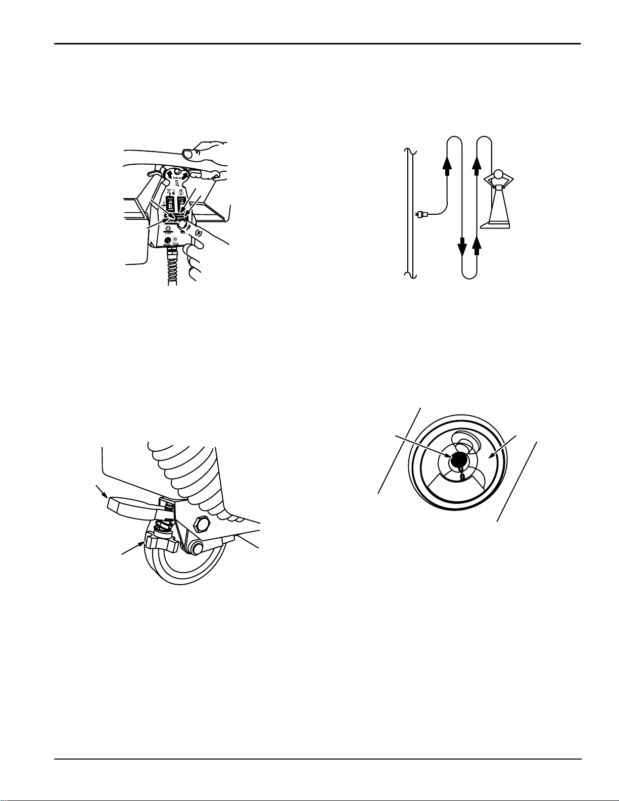
A
C
D
E
C
B
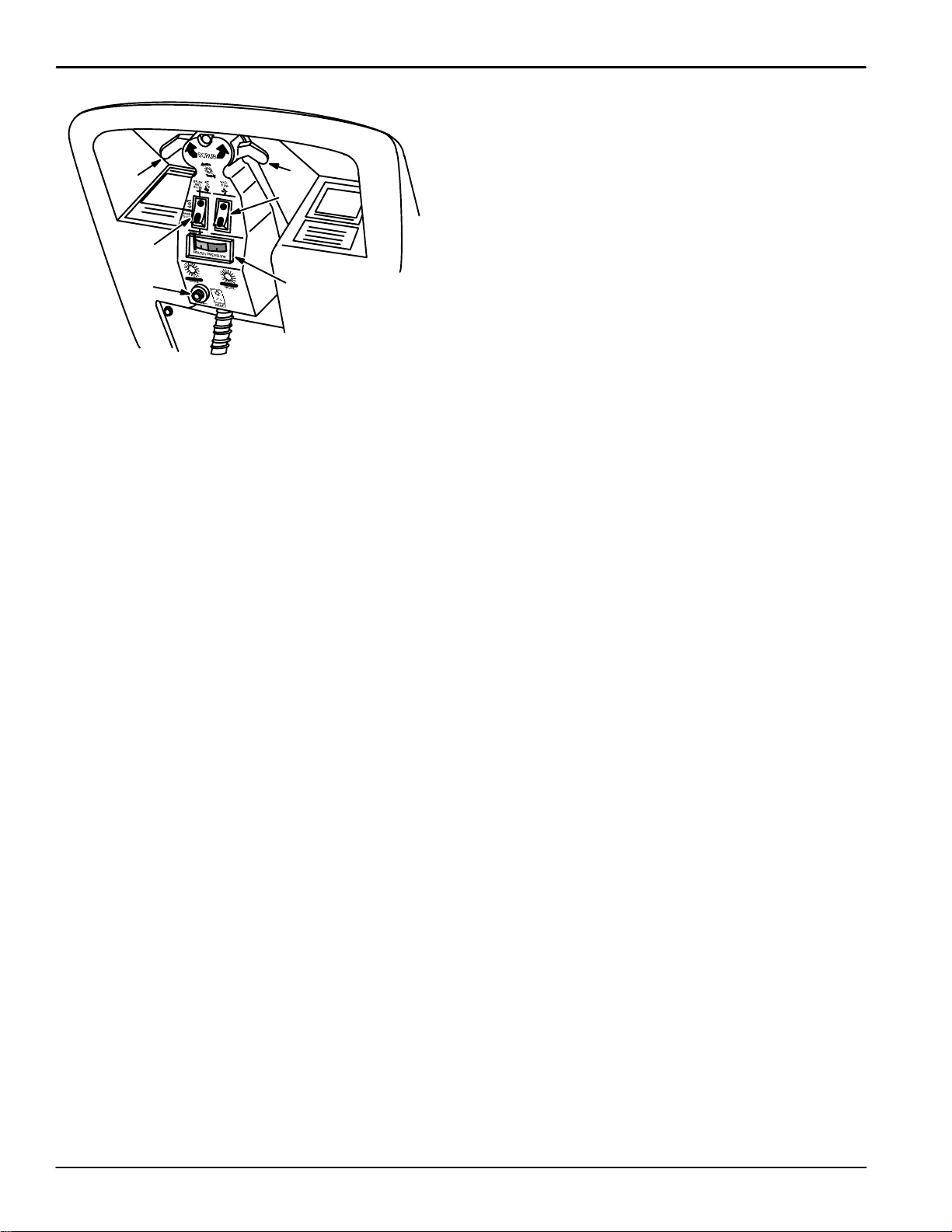
CONTROL PANEL
A. Mode Switch
B. Vacuum Fan Switch
C. Brush/Solution Lever(s)
D. Brush Pressure Gauge
E. Brush Circuit Breaker
MODE SWITCH:
The mode switch controls various scrubbing functions.
For normal scrub operation, place the mode switch in
the BRUSH AND WATER (TOP) position. In this
position, both brush and solution pump will operate
when either brush/solution lever is activated. Both
functions will stop when the lever(s) are released.
For double scrub operation, place the mode switch in
the BRUSH ONLY (CENTER) position. When the
lever(s) are activated, only the brush will operate;
solution will not flow.
For attachment option use, place the mode switch in
the WAND (BOTTOM) position. Only the solution
pump will operate in this position.
NOTE: Make sure solution dispensing tube is
disconnected from the female quick disconnect, or the
option is attached to female quick disconnect,
otherwise solution will immediately begin to flow onto
the floor until the tank is emptied.
VACUUM FAN SWITCH:
The vacuum fan switch controls the vacuum fan.
Press the bottom (I) of the switch to turn on the
vacuum fan. Press the top (O) of the switch to turn off
the vacuum fan.
BRUSH/SOLUTION LEVER(S):
The machine has two levers under the machine
handles at the top of the control panel. The
brush/solution lever(s) turn on the scrub brush and the
solution pump. One or both of the levers can be used
to start the scrub brush and solution pump when the
MODE switch is in the BRUSH AND WATER position.
Only the brush will run when the lever(s) are operated
if the MODE switch is in the BRUSH ONLY position. In
the WAND position, neither the brush nor solution
pump are activated by the lever(s).
BRUSH PRESSURE GAUGE:
The brush pressure gauge indicates the pressure of
the scrub brush on the floor. The brush pressure
needle should be at the top of the green zone for the
best scrubbing results.
BRUSH CIRCUIT BREAKER:
The brush circuit breaker protects the brush motor
from overload. If the brush pressure is too high, the
brush circuit breaker will trip and the scrub brush will
stop. To reset the brush circuit breaker, press the
circuit breaker reset button on the circuit breaker. It
may be necessary to allow the circuit breaker to cool
down before resetting, or it may trip again. Reduce the
brush pressure before resuming scrubbing and check
the brush for obstructions.
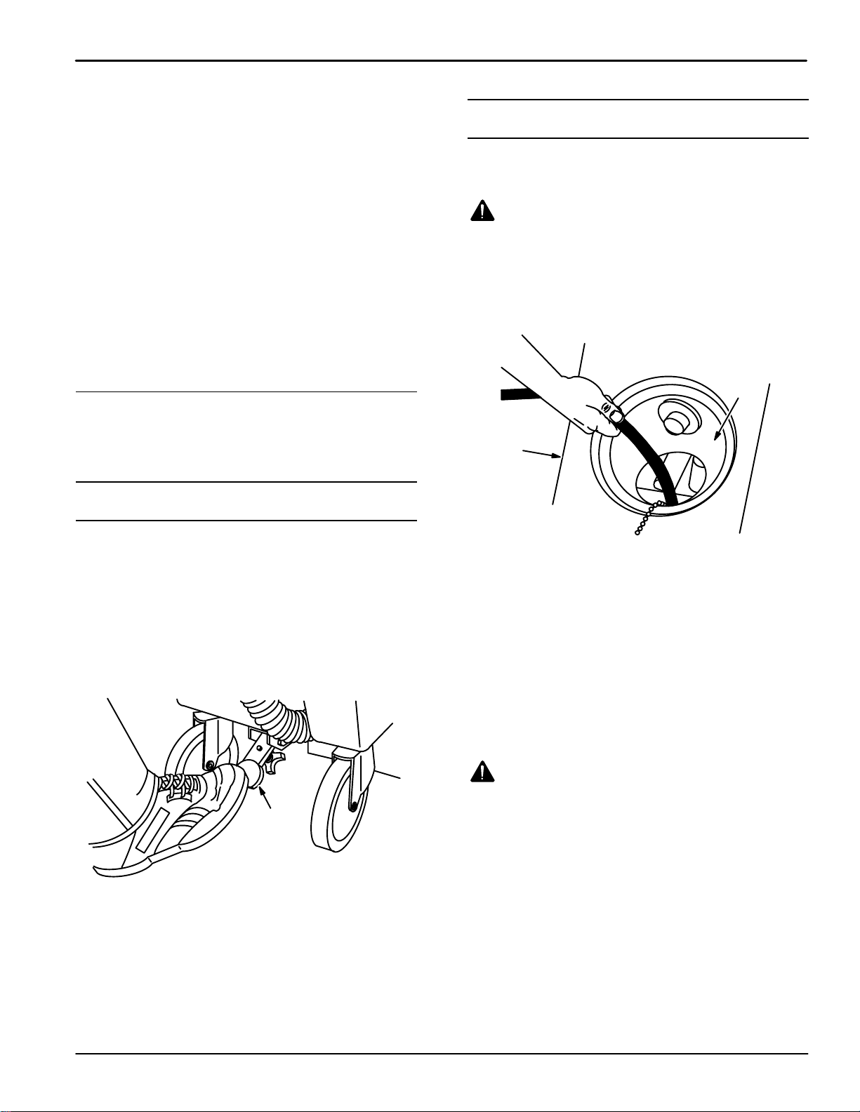
SCRUB HEAD LIFT LEVER:
The scrub head lift lever raises the scrub head off the
floor. Raise the scrub head with the scrub head lift
lever when transporting the machine from place to
place, and when the machine is not being used. To
raise the scrub head, step on the scrub head lift lever.
To lower the scrub head, pull the lever up with the toe
of your shoe.
BRUSH DOWN PRESSURE KNOB:
The brush down pressure knob adjusts the pressure of
the scrub brush against the floor. The brush down
pressure knob is located on the underside of the scrub
head lift lever. To increase the scrub brush pressure,
turn the pressure knob to the left. To decrease the
scrub brush pressure, turn the knob to the right.