Wired Remote Controller GIA-XK19
3
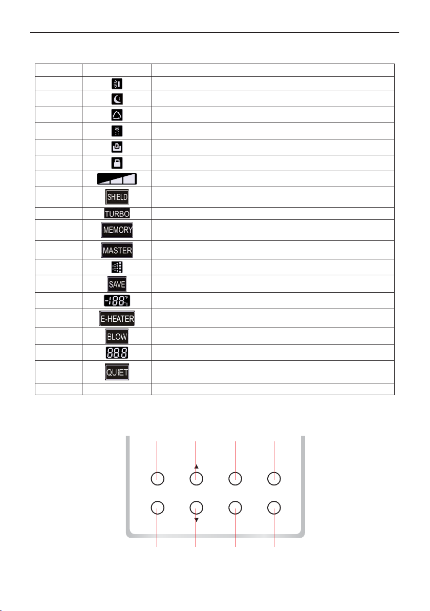
2.2 Function of the Buttons
Table 2
No. Name Function
1 Enter/Cancel Function selection and cancellation.
2ŸķRunning temperature setting of the indoor unit, range:16 30ć
ĸTimer setting, range:0.5-24 hr.
6ź
3 Fan Setting of the high/middle/low/auto fan speed.
4 Mode Setting of the Cooling/Heating/Fan/Dry/Auto mode of the indoor unit.
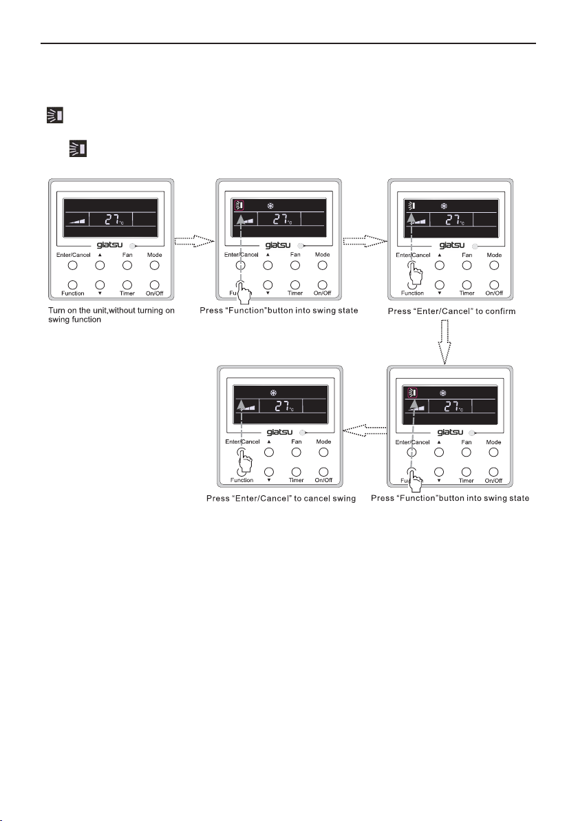
5 Function Switchover among the functions of Turbo/Save/E-heater/Blow etc..
7Timer Timer setting.
8 On/Off Turn on/off the indoor unit.
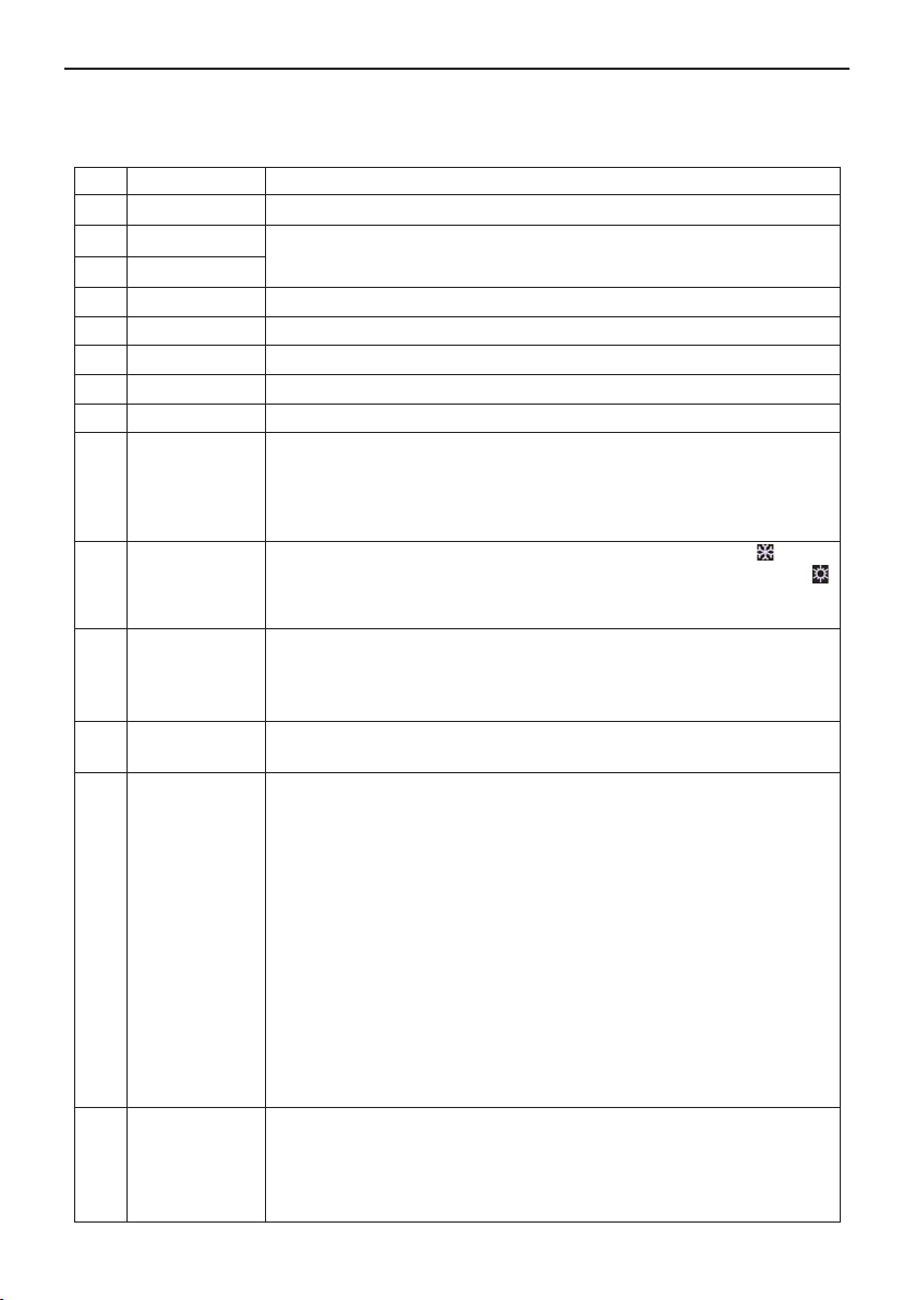
4+2 Ÿ0RGH
Press them for 5s under off state of the unit to Enter/Cancel the Memory
function(If memory is set, indoor unit after power failure and then power
recovery willresume the original setting state. If not, the indoor unit is
defaulted to be off after power recovery. Memory off is default before
delivery.).
3
+6 )DQź
By pressing them at the same time under off state of the unit, will be
displayed on the wired remote controller for the cooling only unit, while
will be displayed on the wired remote controller for the cooling and heating
unit.
2
+6 Ÿź
Upon startup of the unit without malfunction or under off state of the
unit,press them at the same time for 5s to enter the lock state, in which
case, any other buttons won’t respond the press. Repress them for 5s to
quit this state.
4+6 0RGHź Under OFF state, the Celsius and Fahrenheit scales can be switched by
SUHVVLQJ³0RGH´DQG³ź´IRU¿YHVHFRQGV
5+7 Function+Timer
Under OFF state, it is available to go to the commissioning status by
SUHVVLQJ³)XQFWLRQ´DQG³7LPHU´IRU¿YHVHFRQGVDQGOHW³´GLVSOD\HGRQ
the temperature display area by pressing “Mode”, then adjust the options
ZKLFKLVVKRZQRQWKHWLPHUDUHDE\SUHVVLQJ³Ÿ´DQG³ź´7KHUHDUHWRWDOO\
four options, as follows:
ķIndoor ambient temperature is sensed by the return air temperature
sensor ( 01 displayed on the timer area).
ĸIndoor ambient temperature is sensed by the wired controller (02
displayed on the timer area).
ĹThe return air temperature sensor is selected under the cooling, dry, or
fan mode; while the wired controller temperature sensor is selected under
the heating or auto mode. (03 is displayed on the timer area).
ĺThe wired controller temperature sensor is selected under the cooling,
dry, or fan mode; while the return air temperature sensor is selected under
the heating mode. (04 is displayed on the timer display area).
5+7 Function+Timer
Under OFF state, it is available to go to the commissioning status by
pressing “Function” and “Timer” for five seconds. Press “Mode” button to
until “01” icon is shown at the temperature display area. The setting status
ZLOOEHVKRZQDWWLPHU DUHD3UHVV ³Ÿ´DQG³ź´EXWWRQWRDGMXVWDQG WZR
options are available: ķThree low levels (01) ; ĸThree high levels (02).