manuals.online logo
Brands
  1. Home
  2. •
  3. Brands
  4. •
  5. Giant
  6. •
  7. Industrial Equipment
  8. •
  9. Giant 22947 User manual

Giant 22947 User manual

Models
22947(H), 22948(H), 22949(H) & 22950(H)
Adjustable Unloader
Construction Characteristics
·Compact in size
·Interchangeable Valve Bodies
·Connection for pressure gauge, pressure switch and ow switch
Specications
Unloader Pressure Range
PSI (bar)
Maximum
Flow
GPM (L/min)
Minimum
Flow
GPM (L/min)
Maximum
Temperature
°F (°C)
22947(H) 300-1160 (20-80) 60 (225) 2.1 (8) 160 (70)
22948(H) 600-1600 (40-110) 60 (225) 2.1 (8) 160 (70)
22949(H) 1600-3200 (110-220) 32 (120) 2.1 (8) 160 (70)
22950(H) 3200-5800 (220-400) 16 (60) 2.1 (8) 160(70)
non-handwheel version shown
22947(H), 22948(H), 22949(H), 22950(H) Dimensions - in (mm)
Handwheel
Versions Non-Handwheel Versions
22947, 22948, 22949 and 22950
Non-Handwheel Versions Cut-through View and Parts
Item Part # Description Quantity
1 06730 Casing 1
2 12042 Tension Plug 2
2A 12043 Spring Tension Disc 2
3 12281 Retainer, Valve 1
3A 06732 Retainer, Discharge Valve 1
4 12045 Spring, Discharge Valve 1
4A 12118 Spring, Inlet valve 1
5 12046-0100 Ball Valve, Inlet (22947/22948) 1
5 12047-0100 Ball Valve, Inlet (22949/22950) 1
5A 05357 Spacer Disc 1
6 06733 Valve, Discharge 1
7 12282 Valve Seat, Discharge 1
8 06734 Valve Seat, Inlet (22947/22948) 1
8 06745 Valve Seat, Inlet (22949) 1
8 06746 Valve Seat, Inlet (22950) 1
9 12053 Cylinder 1
10 12054 Guide 1
11 06577 O-Ring 3
12 12056 Support Ring 2
13 12057-0001 O-Ring, Discharge Valve Seat 1
14 06736 O-Ring 2
15 12059 Piston 1
15 04846 Piston Body (22947) 1
16 12060 Spacer(22947) 1
16 12284 Spacer (22948/22949/22950) 1
17 04847 O-Ring for 15 (22947) 1
17 12283 Packing (22948/22949/22950) 1
17A 04848 Support Ring (22947) 2
18 06737 Piston Rod 1
19A 22618 O-Ring, Valve Stem 1
19B 12064 Spacer, Valve Stem 2
19C 12065 Key 1
19D 12066 Tension Sleeve 1
20 12067 Support Ring 1
20A 06738 Allen Screw 4
20B 01011-0400 Washer, Spring 4
21 12070 Disc 1
22 04850 Spring, Silver (22947) 23
22 12071 Spring, Yellow (22948) 19
22 12072 Spring, Red (22949) 19
22 12073 Spring, Orange (22950) 19
23 12074 Nut, Adjusting 1
23A+06739 Spacer Disc, 0.2mm 1
23B+06740 Spacer Disc, 0.5mm 2
23C+06741 Spacer Disc, 1.0mm 2
23D+06742 Spacer Disc, 5mm 1
24 06743 Nut, Locking 1
24A 06744 Tension Pin 1
25 07423-0100 Plug, 1/4" 6
25A 07161 Washer 6
+ May not be present. Quantity may vary.
Repair Kits
Unloader Kit Number Parts included:
22948/22949/22950 09619 11,12,13,14,17,19A,19D
22947 09813 4,4A,5,6,11,12,13,14,17, 17A
19A,19B,19D
22948 12081 4,4A,5,6,11,12,13,14,17,
19A,19B,19D
22949 & 22950 12082 4,4A,5,6,11,12,13,14,17,
19A,19B,19D
Sealing of Piston
Body for 22947
22947H, 22948H, 22949H and 22950H
Handwheel Versions Cut-through View and Parts
Item Part # Description Quantity
1 06730 Casing 1
2 12042 Tension Plug 2
2A 12043 Spring Tension Disc 2
3 12281 Retainer, Valve 1
3A 06732 Retainer, Discharge Valve 1
4 12045 Spring, Discharge Valve 1
4A 12118 Spring, Inlet valve 1
5 12046-0100 Ball Valve, Inlet (22947/22948) 1
5 12047-0100 Ball Valve, Inlet (22949/22950) 1
5A 05357 Spacer Disc 1
6 06733 Valve, Discharge 1
7 12282 Valve Seat, Discharge 1
8 06734 Valve Seat, Inlet (22947/22948) 1
8 06745 Valve Seat, Inlet (22949) 1
8 06746 Valve Seat, Inlet (22950) 1
9 12053 Cylinder 1
10 12054 Guide 1
11 06577 O-Ring 3
12 12056 Support Ring 2
13 12057-0001 O-Ring, Discharge Valve Seat 1
14 06736 O-Ring 2
15 12059 Piston 1
15 04846 Piston Body (22947) 1
16 12060 Spacer (22947) 1
16 12284 Spacer (22948/22949/22950) 1
17 04847 O-Ring for 15 (22947) 1
17 12283 Packing (22948/22949/22950) 1
17A 04848 Support Ring (22947) 2
18 04849 Piston Rod 1
19A 22618 O-Ring, Valve Stem 1
19B 12064 Spacer, Valve Stem 2
19C 12065 Key 1
19D 12066 Tension Sleeve 1
20 12067 Support Ring 1
20A 06738 Allen Screw 4
20B 01011-0400 Washer, Spring 4
21 12070 Disc 1
22 04850 Spring, Silver (22947) 23
22 12071 Spring, Yellow (22948) 19
22 12072 Spring, Red (22949) 19
22 12073 Spring, Orange (22950) 19
23 04851 Spacer Sleeve 1
23C+04852 Spacer Disc, 1.0mm 2
23D+04853 Spacer Disc, 5mm 1
24 04854 Nut, Locking 2
24A 04855 Tension Pin 1
24B 04856 Protective Sleeve 1
25 07423-0100 Plug, 1/4" 6
25A 07161 Washer 6
27 04857 Handwheel 1
+ May not be present. Quantity may vary.
Repair Kits
Unloader Kit Number Parts included:
22948/22949/22950 09619 11,12,13,14,17,19A,19D
22947 09813 4,4A,5,6,11,12,13,14,17, 17A
19A,19B,19D
22948 12081 4,4A,5,6,11,12,13,14,17,
19A,19B,19D
22949 & 22950 12082 4,4A,5,6,11,12,13,14,17,
19A,19B,19D
Sealing of Piston
Body for 22947
Giant Industries, Inc.
900 N. Westwood Ave.
Toledo, Ohio 43607
PHONE (419) 531-4600
FAX (419) 531-6836
www.giantpumps.com
© Copyright 2017 Giant Industries, Inc.
08/19 22947-50.indd
Operation
The whole discharge must be guided through the valve. Should the actual operating pressure exceed the adjusted operating pressure, the valve then
acts as a pressure regulator. The valve switches to pressure-free bypass operation when the spray gun shuts off and the spray pressure between
gun and valve remains idle.
The valve can be operated together with several spray guns. It is also possible to connect several pumps to one common discharge line.
IMPORTANT! Valves are NOT SET when delivered. They become a SAFETY COMPONENT only after adjustment on the machine by trained
personnel.
Service and Adjustment
Re-servicing and adjusting work is only to be carried out by skilled tradesmen.
Safety Instructions
Observe direction of ow. The bypass must under no circumstances be closed or tted with any shut-off device.
Continuous bypass operatoin without releasing the water can cause the liquid to heat up which in turn could damage the unit and
endanger persons.
Possible preventive measures:
1.) Limit the bypass duration (max. temperature 140 °F/60 °C); the duration is to be calculated by the operator and in conjunction with the operating
conditions.
2.) Use ttings (e.g. thermal valve on water inlet) to avoid heat increase.
To Adjust Pressure
1.) Open valve so that it is completely tension-free, i. e. loosen nut (24) and adjusting nut (23) so that the piston rod can be moved by hand.
2.) Spring pack is tensioned by adjusting nut (23) while the pump is running and with open gun (if more than one gun is used, all have to be open)
until required operating pressure is attained and no more water runs out on the bypass side. Then lock nut (24) to adjusting nut (23). If the nozzle
hole corresponds exactly to the ow-rate and pressure of the pump, no more water will run out over the bypass after the required pressure has
been attained.
If the nozzle hole is too small and the whole output won’t go through the nozzle after the max. pump pressure has been reached, on no account is
the valve to be adjusted higher than the max. operating pressure of the pump. In this case, the bypass should be partially left open. It is however,
advisable to install suitable nozzles.
To Renew Piston Rod Seals and Sleeves
Unscrew nuts (24+23). Remove spring pack (22). With a 6mm allen wrench, unscrew the 4 inner hexagon screws (20A) and remove spring support
(20). Remove woodruff key (19C) and remove inlet tensioning plug (2). Remove spring (4A), ball (5) and spacer disc (5A). Push out piston rod (18)
downwards together with inner parts (8, and 9). Remove piston body (15) with a size 19 wrench and pull piston rod out of guide case (10). Cut out
worn seals and replace. Then carefully clip O-ring (19A) and support rings (19B) onto the piston rod. Note order of installation. For 22948, 22949 and
22950, put packing (17) on piston rod (18). For 22947, put o-ring (17) and support ring (17A) on piston rod (18). Re-install guide sleeve (10) and
spacer (16). Check casing (1) surfaces and inner parts for dirt or damage as this will cause the seals to wear out quickly. Check O-rings (11&14) and
support rings (12) and replace as necessary. Remount piston body to piston rod with Loctite 648. Re-assemble in reverse order. Grease all parts
lightly with Silicone before reinstalling.
To Check and Replace Valves
Remove the plugs (2) and check whether the balls (5) or valve plate (6) are worn out. Remove valve seats (8, 7) with clipring pliers and check surfaces
for damage. Check O-rings (11) and replace as necessary.
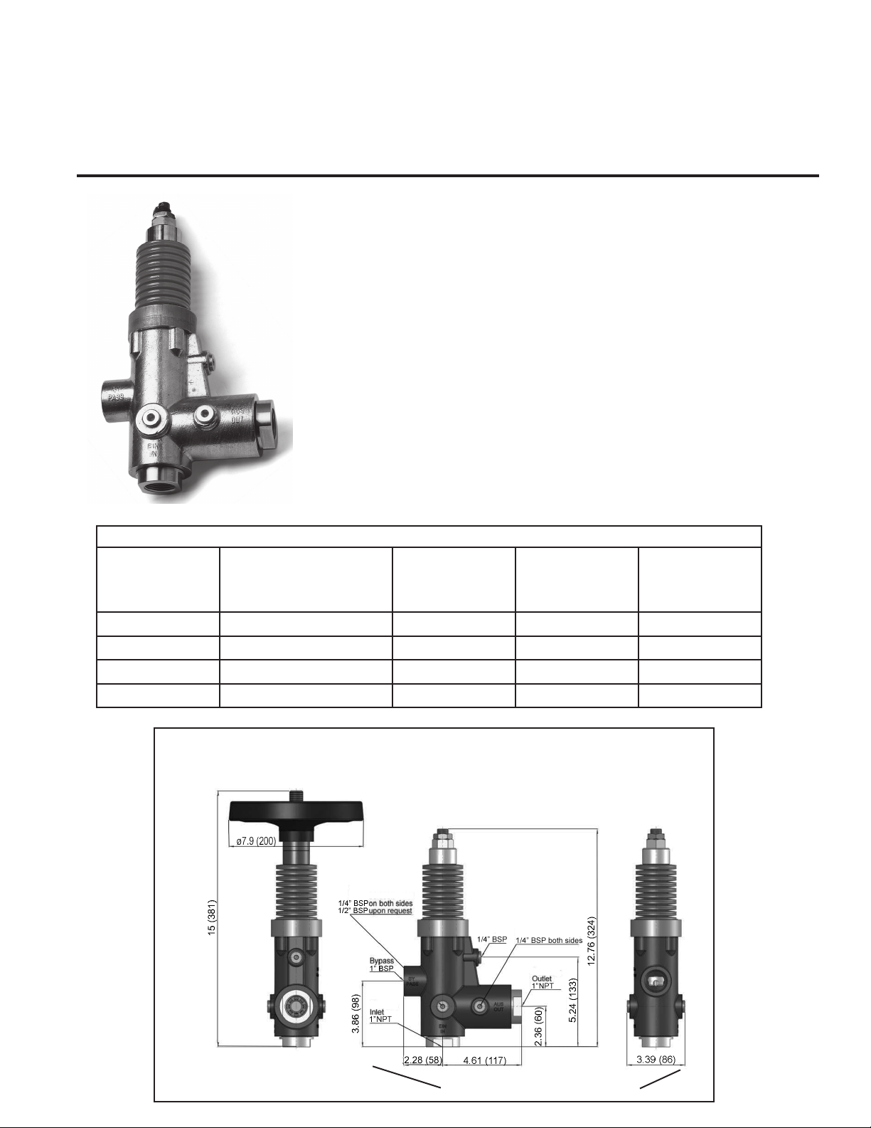
22947(H), 22948(H), 22949(H), 22950(H) Operation and Maintenance
Troubleshooting Guide
Problem Cause Remedy
Valve switched
repeatedly when gun
is closed
Leaky Gun Repair gun
Leaky pressure pipe Seal pressure pipe
Leaky sleeve Replace o-rings
Worn out kick-back valve body Replace kick-back valve body or
o-ring or examine valve seat
Leaky seal (12,14) Renew seal
Leaky piston rod Defective o-ring/support ring Replace piston rod seals and ex-
amine surfaces in guide plug
Leaky bypass at
nominal pressure
nozzle too small, too much water Install larger nozzle
Worn out bypass valve Examine and renew as necessary,
ball (5) and bypass valve body (8)
Pressure Guage
shows high pressure
peaks when shutting
off gun
Valve set too high above operating
pressure
Turn back adjusting nut (23) and
hexagon nut (24) or handwheel
Dirty valve Clean valve (remmoving lime
deposits, etc.) Grease parts before
reinstalling

This manual suits for next models

8

Other Giant Industrial Equipment manuals

Giant TURBO LASER User manual

Giant

Giant TURBO LASER User manual

Giant T5025 Manual

Giant

Giant T5025 Manual

Giant P202-4120 User manual

Giant

Giant P202-4120 User manual

Popular Industrial Equipment manuals by other brands

Graphic Whizard PT CR607 Operator's manual

Graphic Whizard

Graphic Whizard PT CR607 Operator's manual

Eaton SONIX Vw2 Technical manual

Eaton

Eaton SONIX Vw2 Technical manual

Amber M32 Installation & maintenance manual

Amber

Amber M32 Installation & maintenance manual

FMS RTM X42.Modbus Installation manual and operating instructions

FMS

FMS RTM X42.Modbus Installation manual and operating instructions

Afag LF9 Operating & installation instructions

Afag

Afag LF9 Operating & installation instructions

ABB HT569313 Operation manual

ABB

ABB HT569313 Operation manual

Valeport fastCTD Profiler operating manual

Valeport

Valeport fastCTD Profiler operating manual

Afriso EURO-INDEX KAV operating instructions

Afriso EURO-INDEX

Afriso EURO-INDEX KAV operating instructions

Dodge SLEEVOIL RXT instruction manual

Dodge

Dodge SLEEVOIL RXT instruction manual

Graco ProControl 1KS installation guide

Graco

Graco ProControl 1KS installation guide

ABB HT607806 Operation manual

ABB

ABB HT607806 Operation manual

Festo HMPL-12-KP Series operating instructions

Festo

Festo HMPL-12-KP Series operating instructions

Larson Electronics HLX-SWG-EB Series instruction manual

Larson Electronics

Larson Electronics HLX-SWG-EB Series instruction manual

Graco Therm-O-Flow 20 Instructions - parts

Graco

Graco Therm-O-Flow 20 Instructions - parts

MULTIQUIP G55H Operation manual

MULTIQUIP

MULTIQUIP G55H Operation manual

M-system M5XADS instruction manual

M-system

M-system M5XADS instruction manual

Lennox EL195UHNE Series manual

Lennox

Lennox EL195UHNE Series manual

Milnor MWF100C7 manual

Milnor

Milnor MWF100C7 manual

manuals.online logo
manuals.online logoBrands
  • About & Mission
  • Contact us
  • Privacy Policy
  • Terms and Conditions

Copyright 2025 Manuals.Online. All Rights Reserved.