Giant P202-4120 User manual

Models
P202-4120, P202-4121,
and P202-4127
Contents:
Installation Instructions: page 2
Pump Specications: page 3
Exploded View: page 4
Parts List: page 5
Kits: page 5
Repair Instructions: page 6
Dimensions: page 7
Warranty Information: back page
Triplex Plunger Pump
Operating Instruction
Repair and Service Manual
Updated 10/22
P202-4120 = Nitrile O-Rings
P202-4121 = Viton O-Rings
P202-4127 = Isolast O-Rings

2
INSTALLATION INSTRUCTIONS
Safety Rule: The pump is not to be used without a safety valve.
Operation and Maintenance
Check oil level prior to starting and ensure trouble-free uid supply.
The viscosity and the vapor point of the conveyed medium determine the required input pressure.
The valves of the pump open at a pressure of 5.8 PSI (0.4 bar). This resistance must also be considered
when calculating the input pressure. The maximum input pressure is 145 PSI (10 bar).
Oil: Use only 9.5 ounces (0.28 liters) of industrial gear oil SAE90 (Giant’s part number 01154) or as per
ISO VG e.g. Aral Degol BG 150 before starting.
Initial change after 50 operating hours and then every 500 operating hours or 1 year if used less.
Caution when operating in damp places or with high temperature uctuations. Oil must be changed
immediately should condensate (frothy oil) occur in the gear box.
Safety Rules
Pump operation without safety valve as well as any excess in temperature or speed limits, automatically
voids the warranty. The safety valve must be regulated in accordance with the guidelines for liquid
spraying units so that the maximum admissible operating pressure can not be exceeded by more than
10%.
When the pump is in operation, the drive shaft end and the coupling must be covered up by either a
contact-protector or by a coupling bell. Pressure in discharge line and in pump must be at zero before any
maintenance to the pump takes place. Close up suction line. Disconnect fuses to ensure that the driving
motor does not get switched on accidentally.
Make sure that all parts on the pressure side of the unit are vented before starting the pump. In order to
prevent air, or an air-water mixture being absorbed and to prevent cavitation occurring, the pump-NPSHR
suction head and water temperature must be kept under control.
Cavitation and/or compression of gases lead to uncontrollable pressure-kicks which can ruin
pump and unit parts and also be dangerous to the operator or anyone standing nearby.
Before pumping inammable, explosive and toxic media - the pump manufacturer must under
all circumstances be consulted with regard to the resistance of the pump material. It is the
responsibility of the equipment manufacture and/or operator to ensure that all pertinent safety
regulations are adhered to.
For additional information on how this pump functions, go to:
https://www.giantpumps.com/wp-content/uploads/2019/06/P201_P202_P204_P213-Function-Description.pdf

3
Pump Specications - P202-4120, P202-4121 and P202-4127
U.S. Metric
Volume............................................................... 1.27 GPM* ......................... 4.8 L/min*
Discharge Pressure........................................... 3190 PSI ............................ 220 Bar
Crankshaft Speed..........................................................................................1450 RPM
Plunger Diameter............................................... 0.47”................................... 12mm
Plunger Stroke................................................... 0.39”................................... 10mm
Crankshaft Diameter.......................................... 0.98”................................... 24mm
Key Width .......................................................... 0.31”................................... 8mm
Crankshaft Mounting .....................................................................................Either side
Crankshaft Rotation.........................................................Top of Pulley Towards Fluid End
Temperature of Pumped Fluids ......................... 140 oF................................. 60 oC
Inlet Ports ......................................................................................................(2) 1/2” BSP
Discharge Ports.............................................................................................(2) 1/4” BSP
Weight ............................................................... 13.9 lbs. ............................. 10 kg
Crankcase Oil Capacity..................................... 9.5 Ounces......................... 0.28 Liters
* Theoretical displacement per revolution is approximately 0.115 ounce (3.39 cm3)
Important! The 1/8” rinsing connection on both sides serves to place a separating agent (e.g.
DOP) behind the medium seal on the suction side. This stops leakage (e.g. with Iscocyanate)
from crystallizing. When pumping dierent types of Freon, the pressure in the rinsing system
should be approximately 7.25 PSI (0.5 bar) higher than on the suction side of the pumped me-
dium.
To vent the pump easily on the discharge side, it is recommeded to install a T-piece with a high-
pressure cut-o tap as close as possible to the discharge port.
HORSEPOWER RATINGS:
The rating shown are the power
requirements for the pump. Gas engine
power outputs must be approximately
twice the pump power requirements
shown above.
We recommend a 1.15 service factor be
specied when selecting an electric motor as
the power source. To compute specic pump
horse power requirements, use the following
formula:
HP = (GPM X PSI) / 1450
Horsepower Requirements
P202-4120, P202-4121 and P202-4127
RPM GPM 500 PSI 1000 PSI 2000 PSI 3190 PSI
725 0.64 0.22 0.44 0.88 1.4
900 0.79 0.27 0.55 1.09 1.7
1200 1.05 0.36 0.72 1.5 2.3
1450 1.27 0.44 0.88 1.8 2.8

4
Exploded View - P202-4120, P202-4121 and P202-4127

5
ITEM PART NO. DESCRIPTION QTY.
26 05861 Rod Seal (P202-4120) 3
26 05861-0010 Rod Seal (P202-4121) 3
26 04927-0005 Rod Seal, Isolast 3
(P202-4127)
27 05862 Guide Band 3
28 05863 Guide Sleeve 3
29 08416 O-Ring (P202-4120) 3
29 08416-0001 O-Ring (P202-4121) 3
29 04928-0005 O-Ring, Isolast (P202-4127) 3
30 05864 Rod Seal (P202-4120) 3
30 05864-0010 Rod Seal (P202-4121) 3
30 04929-0005 O-Ring, Isolast (P202-4127) 3
31 05865 Seal Retainer 3
32 05866 Inlet Casing 1
33 05867 Plug, 1/2” BSP 1
34 05868 Seal, 1/2” BSP 1
35 07423-0100 Plug, 1/2” BSP 2
36 05869 Seal, 1/2” BSP 2
37 05870 Valve Seat 3
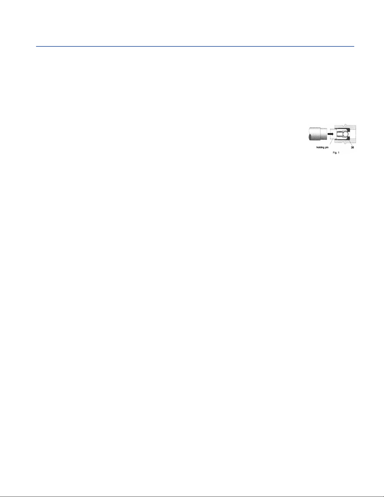
38 03520 Valve Assembly 6
39 05871 O-Ring (P202-4120) 3
39 05871-0001 O-Ring (P202-4121) 3
39 05871-0005 O-Ring, Isolast (P202-4127) 3
40 12017 O-Ring (P202-4120) 3
40 11507-0001 O-Ring (P202-4121) 3
40 11507-0005 O-Ring (P202-4127) 3
41 05872 Discharge Casing 1
42 05873 Hexagon Socket Screw 8
44 06589 Socket Plug, 1/2” BSP 1
45 05874 Seal, 1/8” BSP 1
Spare Parts List - P202-4120, P202-4121 and P202-4127
ITEM PART NO. DESCRIPTION QTY.
1 08300CA Crankcase, Anodized 1
2 08301 Oil Dipstick with O-Ring 1
3 08302A Crankcase Cover, Anodized 1
3A 07190 Drain Plug and Gasket 1
4 08005 O-Ring 1
5 08185 Oil Drain Plug with Gasket 1
6 07188 Screw, Short Cover 4
6A 07223-0100 Spring Washer 4
7 08303 Bearing Cover 2
8 08491 Sight Glass 1
9 07193 O-Ring for Sight Glass 1
10 07225 Screw with Lock Washer 8
11 08331 Radial Shaft Seal 1
12A 04917 Ball Bearing 1
12B 01086 Ball Bearing 1
13 04920 Crankshaft 1
14 06207 Fitting Key 1
15 08333 Connecting Rod 3
16 05453 Plunger 3
17 08442 Wrist Pin 3
19 08356-0010 Oil Seal 3
20 05855 Spacer ring 3
20A 05856 Plug 3
21 05857 Intermediate Casing 1
22 06717 Seal Ring, gray 3
22A 05858 Seal Ring, black 6
23 07770 O-Ring (P202-4120) 9
23 07770-0001 O-Ring, Viton (P202-4121) 9
23 04926-0005 O-Ring, Isolast (P202-4127) 9
24 05859 Spacer Ring 3
25 05860 Support Ring 3
Seal Repair Kit - P202-4120 - #09711
Item # Part # Description Qty.
22 06717 Seal Ring, gray 3
22A 05858 Seal Ring, black 6
23 07770 O-Ring 9
26 05861 Rod Seal 3
27 05862 Guide Band 3
29 08416 O-Ring 3
30 05864 Rod Seal 3
39 05871 O-Ring 3
40 12017 O-Ring 3
Seal Repair Kit - P202-4121 - #09711-0021
Item # Part # Description Qty.
22 06717 Grooved Seal Ring 3
22A 05858 Grooved Ring 6
23 07770-0001 O-Ring, Viton 9
26 05861-0010 Rod Seal, Viton 3
27 05862 Guide Band 3
29 08416-0001 O-Ring, Viton 3
30 05864-0010 Rod Seal, Viton 3
39 05871-0001 O-Ring, Viton 3
40 11507-0001 O-Ring, Viton 3
Repair Kits - P202-4120 and P202-4121
Seal Repair Kit - P202-4127 - #09711-0027
Item # Part # Description Qty.
22 06717 Seal Ring, gray 3
22A 05858 Seal Ring, black 6
23 04926-0005 O-Ring, Isolast 9
26 04927-0005 Rod Seal, Isolast 3
27 05862 Guide Band 3
29 04928-0005 O-Ring, Isolast 3
30 04929-0005 O-Ring, Isolast 3
39 05871-0005 O-Ring, Isolast 3
40 11507-0005 O-Ring, Isolast 3
Oil Seal Repair Kit - #09144-0010
Item # Part # Description Qty.
19 08356-0010 Oil Seal 3

6
Repair Instructions - P202-4020, P202-4021 and P202-4127
Additional repair instructions shown on Giant’s website:
(https://www.giantpumps.com/wp-content/uploads/2019/06/P202-P204-4020_4021-repair-instructions.pdf).
1. Suction and Discharge Valves
Remove hexagon socket screws (42), pull o discharge casing (41) towards the front. Pull valve seat (37)
out of suction casing (32). The complete valve (38) which was pressed into place must be re moved by
carefully drilling it out of the valve seat (37) or plunger (16) with a ø7.8 drill. Examine o-rings (39,40) on
valve seat and replace if necessary.
The new valve (38) must be inserted into the bore so that it is level. The holding pin must then be pressed
in to be level with the help of a tool (hammer or insert tool-see g. 1). When reassembling tighten hexagon
socket screw (42) to 88-106 in-lbs. (10-12 Nm).
2. Grooved Seal
Remove hexagon socket screws (42), pull o discharge casing (41), valve seat (37),
suction casing (32) and intermediate casing (21) towards the front. Pull valve seat (37)
out of suction casing (32). Remove intermediate casing (21) from guide sleeve (28),
then pull out seal adaptor (31) from suction casing (32). Pry seal rings (22/22A) as well as rod seals (30)
out of the guide sleeve (28), the spacer ring (20), the guide sleeve (31) and suction casing (32).
Important! Examine surfaces of plungers (16). Damaged surfaces lead to rapid seal wear. If the
plunger(s) (16) is (are) worn, the complete plunger must be replaced -see 3b.
Important! New seals must be installed with utmost care. Even minute scratches on the inner/outer seal
surface can cause leakage. Carefully note the sequence and position of seal rings. Place the cases holding
the seals onto the plungers.
When reassembling tighten hexagon socket screw (42) to 88-106 in-lbs. (10-12 Nm).
3.Gear and Plunger
If oil leaks where the plunger (16) protrudes out of the gear, gear seals (19) and plungers have to be
examined and replaced if necessary.
a) Oil Seal
Remove plug (3A) and drain oil. Pull o discharge casing (41), valve seat (37), suction casing (32), guide
sleeve (28) and intermediate casing (21) towards the front. Take spacer ring (20) o plunger, remove
plunger as described under 3b and pry out gear seal (19) with a screwdriver. Note the exact sequence of
assembly.
b) Plungers
Remove plug (3A) and drain oil. Remove gear cover (3). To dismantle crankshaft (13), use an insert tool
to remove bearing cover (7). Carefully move the crankshaft axialwise using a rubber hammer or insert
tool at the same time threading it carefully through the connecting rods (15), taking care not to force the
crankshaft or bend the connecting rods. Remove and dismantle connecting rods and plungers. Replace
worn parts. Put crankshaft in again through the connecting rods and press in bearings (12A,12B) on each
side. Then install radial shaft seal (11), oil sight glass (8 not shown) and bearing cover (7).
4. To Change Crankshaft Side
The crankshaft end is on the left side of the pump when viewed from behind. Should the crankshaft have to
be on the right side, proceed as follows:
Switch stopper plugs (33/35) and seals (34/36) into the opposite connection. The suction line should
always run to the pump from below and the discharge line from above to ensure the pump is optimally
vented.
The leakage holes in the spacer rings (20) must be open and facing downward so that leakage liquid can
drain.
Close upper holes with plastic plugs (20A).
Interchange plug (5) and oil ller plug (2) and turn gear cover (3) 180° around.

7
Dimensions - Inches (mm) - P202-4120, P202-4121 and P202-4127

10/22 P202-4120_21_27.indd
GIANT INDUSTRIES, INC., 900 N. Westwood Ave., Toledo, Ohio 43607
PHONE (419) 531-4600, FAX (419) 531-6836, www.giantpumps.com
© Copyright 2022 Giant Industries, Inc.
GIANT INDUSTRIES LIMITED WARRANTY
Giant Industries, Inc. pumps and accessories are warranted by the manufacturer to be free from
defects in workmanship and material as follows:
1. Five (5) years from the date of shipment for all pumps used in portable pressure
washers with NON-SALINE, clean water applications.
2. Two (2) years from the date of shipment for Giant pumps used in car wash
applications.
3. One (1) year from the date of shipment for all other Giant industrial and
consumer pumps.
4. Six (6) months from the date of shipment for all rebuilt pumps
5. Ninety (90) days from the date of shipment for all Giant accessories.
This warranty is limited to repair or replacement of pumps and accessories of which the
manufacturer’s evaluation shows were defective at the time of shipment by the manufacturer. The
following items are NOT covered or will void the warranty:
1. Defects caused by negligence or fault of the buyer or third party.
2. Normal wear and tear to standard wear parts.
3. Use of repair parts other than those manufactured or authorized by Giant.
4. Improper use of the product as a component part.
5. Changes or modications made by the customer or third party.
6. The operation of pumps and or accessories exceeding the specications set forth
in the Operations Manuals provided by Giant Industries, Inc.
Liability under this warranty is on all non-wear parts and limited to the replacement or repair of
those products returned freight prepaid to Giant Industries which are deemed to be defective
due to workmanship or failure of material. A Returned Goods Authorization (R.G.A.) number and
completed warranty evaluation form is required prior to the return to Giant Industries of all products
under warranty consideration. Call (419)-531-4600 or fax (419)-531-6836 to obtain an R.G.A.
number.
Repair or replacement of defective products as provided is the sole and exclusive remedy provided
hereunder and the MANUFACTURER SHALL NOT BE LIABLE FOR FURTHER LOSS, DAMAGES,
OR EXPENSES, INCLUDING INCIDENTAL AND CONSEQUENTIAL DAMAGES DIRECTLY OR
INDIRECTLY ARISING FROM THE SALE OR USE OF THIS PRODUCT.
THE LIMITED WARRANTY SET FORTH HEREIN IS IN LIEU OF ALL OTHER WARRANTIES
OR REPRESENTATION, EXPRESS OR IMPLIED, INCLUDING WITHOUT LIMITATION ANY
WARRANTIES OR MERCHANTABILITY OR FITNESS FOR A PARTICULAR PURPOSE
AND ALL SUCH WARRANTIES ARE HEREBY DISCLAIMED AND EXCLUDED BY THE
MANUFACTURER.
WARNING: This product might contain a chemical known to the State of California to cause
cancer, and birth defects or other reproductive harm.
For more information go to www.P65Warnings.ca.gov
This manual suits for next models
2
Table of contents
Other Giant Industrial Equipment manuals
Popular Industrial Equipment manuals by other brands

RINGSPANN
RINGSPANN FRS Series Installation, Lubrication, Maintenance Instructions

Siemens
Siemens SINUMERIK ONE NCU 1760 Equipment manual

ABB
ABB HT613266 Operation manual

Graco
Graco Therm-O-Flow 20 Instructions - parts

Wiedenmann
Wiedenmann Snow Master VARIO 3350 Series Translation of original operating instructions

Simplex
Simplex STS DAY TANK manual

MiTEC
MiTEC WTX-14014539-70-ES Series Operation and maintenance manual

Genesis
Genesis GXT 115 reference guide

Mitsubishi Electric
Mitsubishi Electric M800VW Series Connection and set up manual

Vestil
Vestil D-FORK owner's manual

Carlisle
Carlisle Ransburg 79297 Service manual

Jäger
Jäger Z80-M450.57 K1,2CK manual