Giant J3-90 User manual

Giant J3-90
Almost‐Ready‐to‐Fly
INSTRUCITION MANUAL
Specifications
Wingspan: 91 in (2306mm)
Length: 59in (1503mm)
Wing Area: 1185sq in (76.4sq dm)
Flying Weight (EP): Approx. 12lbs (5300g)

www.valuehobby.com/j3-90.html
Dear Customer,
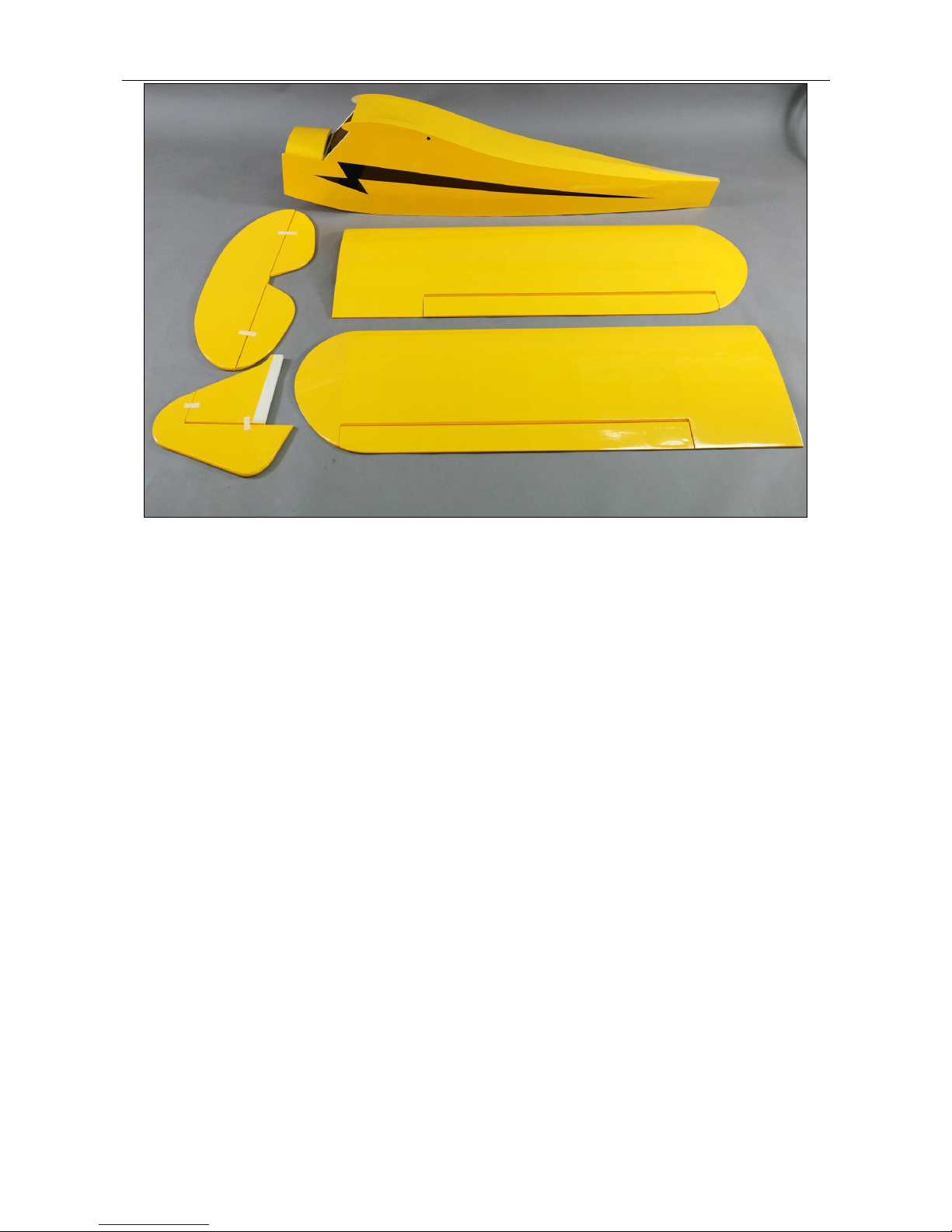
Congratulations on your purchase of Giant J3-90 ARF from Value Hobby. We thank you for your generous
support, and hope you enjoy your new airplane.
At Value Hobby, we hope to offer competitive prices, good performance, and products that you can setup and
use with ease. That’s why we extensively researched and tested this airplane, and suggested all the products
necessary for you to setup properly. We understand that you have many choices when purchasing, and we are
grateful you choose to buy from us.
As vendors, one of the most gratifying things for us is to hear from our customers. We would welcome any
suggestion to help us improve. Please make us aware of any errors and imperfections in the airplane or the
instructions, or about the setup that we suggested. We hope you’ll find our setup suggestions to be helpful, and
enjoy flying your new airplane. Please feel free to contact us at (630) 948‐0947 or email us at
support@valuehobby.com
Disclaimer
By purchasing and/or building this model, user assumes ALL liability and risk involved with this product. This
model should be built and flown by an experienced pilot and only flown at AMA sanctioned sites.
Value Hobby guarantees this model to be free of defects in materials and workmanship at the date of purchase.
This warranty does not cover any parts damaged by use or modifications. In no way shall Value Hobby’s liability
exceed the original cost of the purchased model. Further, Value Hobby reserves the right to modify this
warranty without notice. Value Hobby has no control over the final stages of assembly or the material used for
the final assembly. No liability shall be assumed nor materials used for the final user‐assembled product. By the
act of using the final product the user accepts all resulting liability. Value Hobby, as a R/C product vendor,
provides a top quality airplane and instructions to complete the model. The quality and flight characteristics of
the finished model depend greatly on how it is built; we cannot guarantee the performance for the completed
model and representations are expressed or implied as to the performance of the completed model. If the buyer
is not prepared to accept the liability associated with the use of this product, the buyer is advised to return this
kit immediately, in new and unused condition.
Safety in Assembly
During assembly of this aircraft, you will be asked to use sharp knives and hobby adhesives. Please follow all
safety procedures recommended by the manufacturers of the products you use, and always follow these
important guidelines:
ALWAYS protect your eyes when working with adhesives, knives, or tools, especially power tools. Safety
glasses are the best way to protect your eyes.
ALWAYS protect your body, especially your hands and fingers when using adhesives, knives, or tools, especially
power tools. Do not cut toward exposed skin with hobby knives. Do not place hobby knives on tables or benches
where they can roll off or be knocked off.
ALWAYS have a first‐aid kit handy when working with adhesives, knives, or tools, especially power
tools. ALWAYS keep hobby equipment and supplies out of the reach of children.

www.valuehobby.com/j3-90.html
Safety in Flying
This is NOT a toy! It is a very high‐performance RC airplane capable of high speeds and extreme maneuvers. It
should only be operated by a competent pilot in a safe area with proper supervision.
ONLY fly your aircraft in a safe, open area, away from spectators and vehicles–and where it is legal to
fly. NEVER fly over an unsafe area, such as a road or street.
Never fly too close to yourself or spectators.
Never run your motor inside a house or building with the propeller attached –Remove the prop for safety.
Required Items
CA Glue –Thin and Thick
Epoxy glue
Hobby Knife
Small Phillips Screwdriver
Set Metric Allen Wrenches
Scissors
Small Pliers
Wire Cutters
Masking tape
Optional –Heat gun
Before Starting Assembly
Examination
Unpack your airplane and examine the components. Check for damage of any kind. If you see any
damage, please contact Value Hobby immediately.
Covering
Your airplane was packed in plastic at the factory without any wrinkles in the covering. You may notice some
wrinkles now; more likely, you will notice a few in a day or two or the first time you take the plane out to the
flying field. These wrinkles are the result of wood shrinkage and/or expansion. Balsa wood changes size and
shape slightly as it is exposed to varying humidity in the air. This is a natural property of balsa wood. As your
airplane adjusts to the weather in your part of the world, wrinkles may appear and disappear. Wrinkles may be
removed with the gentle application of heat to the covering material on your airplane. The best tool to use is a
hobby heat gun. Apply the heat gently: the covering material will shrink as you apply the heat, and this will
remove the wrinkles. BE CAREFUL! Too much heat applied too quickly can damage the covering, either by
causing it to pull away from the wood at seams and corners or even by melting it. The covering will shrink at low
temperature with patient application of heat.
Wrinkles in the covering DO NOT affect flight performance.
Remove the canopy before attempting to use heat on your covering! The canopy is made of
thermo‐activated plastic and WILL deform with the application of heat. Do not apply heat to the canopy.
If you need to clean your airplane, we recommend using a damp towel. The paint used on the canopy and cowl
is not safe for all cleaners. In particular, DO NOT use alcohol on these parts, it will remove the paint.

www.valuehobby.com/j3-90.html
RECOMMENDED RADIO EQUIPMENT
Product
SKU
Quantity
Radio
Flysky I6 6CH transmitter and receiver set
FLY-RC-4572
1
Servo
Towerpro MG996R standard servo
TWP-SV-0372
5(nitro)
4 (electric)
Servo
Extension
Universal Servo Extension 18-Inch (Futaba "J" and JR Compatible)
AMS-AC-0562
2
Y-Harness
Universal Servo Y-Harness 12-Inch (Futaba "J" and JR Compatible)
AMS-AC-0870
1
RECOMMENDED Engine SETUP
Product
SKU
Engine
2 stroke 90-108 nitro engine
4stroke 110-120 nitro engine
20-24cc gasoline engine
Battery
GForce 30c 2200mah 2s 6.6V LiFe Receiver LiPO
LYB--LP-3446
Prop
18 x 8 wooden prop
RECOMMENDED Motor SETUP
Product
SKU
Motor
5652-325kv motor (equivalent to 90 size glow engine)
ESC
Hobbywing FlyFun 100A OPTO ESC (No BEC)
HWG-SC-3538
Battery
GForce 30c 2200mah 2s 6.6V LiFe Receiver Battery
LYB--LP-3446
Battery
GForce Elite Series 60C 5000mAh 6S 22.2V LiPO
FLM-LP-4561
Prop
18 x 8 Electric Prop
OPTIONAL ACCESSORIES:
Product
SKU
Charger
GT Power C6 6S LiPO Charger
GTP-CH-1427
Thin CA Glue
Quickie Thin CA
VHB-AC-2097
Medium CA Glue
Quickie Medium CA
VHB-AC-2098
Watt Meter
GT Power 130A Watt Meter
GTP-AC-0591
Connector
T Connector Female
AMS-AC-1914
T Connector Male
AMS-AC-1913
LiPO Bag
LiPO charging bag
VHB-LP-0330

www.valuehobby.com/j3-90.html
1. Wings
2. Fuselage
3. Elevator
4. Rudder and fin

www.valuehobby.com/j3-90.html
Hatch
Cowling
M2.3x8mm self-tapping screw x 4
550cc fuel tank
350mm cable tie x 2
Main landing gear
M4x16mm socket head screw x 4
M4 lock nut x 4
M6 x 35mm axle x 2
Wheel collar x 4
Wheel x 2
Landing gear pant x 2
Front windscreen
Side window
PA2.3x8mm x 4
Wing strut x 2
Center strut support x 2
Red nylon strap x 4
White Nylon strap x 4
M3 x 10mm socket head screw x 6
M3 washer x 6
M2.5 x 12 socket head self-tapping screw x 16
Motor mount
M4 x 25mm socket head screw x 4
M4 x 25 screw x 4
M4 washer x 12
M4 locknut x 4
Steel cable x 1
Fitting x 8
Brass tube x 8
M3 x 16mm socket head screw x 3
M3 x12mm self-tapping socket head screw x 3
M3 locknut x 3
Wing joiner 19 x 800mm
Wing joiner 9 x 135mm
M6 x 25mm nylon screw x 2
Servo hatch x 2
Servo mounting block x 4
M2.3 x 8mm self-tapping screw
1.8 x 915mm elevator servo pushrod
1.8 x 915mm rudder servo pushrod
1.8 x 125mm aileron servo pushrod
1.5 x 385mm throttle servo pushrod
2.5mm elevator joiner
2.1mm easy connector x5
Adjustable control horn x 4
M2 x 16mm socket head screw x 6
M2 x 25mm socket head screw x 6
2mm clevis x 4
M2 x 10mm socket head screw x 4
M2 locknut x 4
Sticker x 1 set
Tail wheel assembly x 1 set

Section1. Aileron Installation
Step1. Remove the coverings as shown.
Step2. Insert four hinges into the wing.
Step3. Apply some thin CA to secure the hinge to
the wing.
Step4. Test fit the aileron to the wing through the
hinge.
Step5.Apply thin CA to secure the aileron to the
wing.
Step6. Repeat the previous step for the other wing
and aileron.

www.valuehobby.com/j3-90.html
Section2. Aileron Servo Installation
Step1. Prepare a servo with servo arm and pushrod
connector installed.
Connect a servo lead extension to the servo lead.
Secure the connectors using a safety clip.
Step2. Locate the servo hatch and two servo
mounting blocks.
(Note: Don’t pick up the wrong side servo hatch.
The servo arm is supposed to be in the center of the
notch after the servo is installed.)
Step3. Use epoxy to glue the block to the hatch. Let
the epoxy full cure before proceeding to the next
step.
Step4. Use two self-tapping M2.3x8mm screws to
secure the block won’t loose.
Step5. Use the screws supplied with the servo to
mount the servo the mounting blocks.
Step6. Thread the servo lead through the wing
panel and out of the wing root.

www.valuehobby.com/j3-90.html
Step7. Secure the hatch the wing using M2.3x8mm
screws.
Step8. Position the control horn on the aileron. Use
the pushrod wire as a guide to align the horn to the
servo arm. Position the horn so the holes align with
the hinge line. Use a felt-tipped pen to mark the
positions for the three mounting bolts.
Step9. Drill the locations marked in the previous
step.
Step10. Attach the control horn using three
M2x25mm socket head screws and control horn
backplate.
Step11. Attach the clevis to the control horn using
M2x10mm socket head screw and M2 nut.
Step12. With the control surface centered, tighten
the screw on the pushrod connector.
Step13. Repeat the previous steps to install the
other aileron servo.

www.valuehobby.com/j3-90.html
Section3. Wing Strut Installation
Step1. Put the wing strut and center strut support in
place and mark the location where the strut
support is against the strut.
Step2. Install the center strut support to the wing
strut using M2.5x12mm self-tapping socket head
screws.
Step3. Install the strut support to the wing using
M2.5x12mm self-tapping socket head screws.
Step4. Install the wing strut to the wing using
M3x10 socket head screws.
Section4. Main landing gear
Installation
Step1. Attach the axle to each landing gear leg with
the included two M6 locknuts. Use threadlock when
assembling the axle.
Step2. Attach the wheel to the axle using two wheel
collars and grub screws.
Step3. Repeat Steps 1 and 2 for the remaining
wheel.

www.valuehobby.com/j3-90.html
Step4. Use thin CA to glue two wheel pants to the
landing gear leg.
Step5. Use four M4x16mm socket head screws and
four M4 nuts to install the landing gear to the
fuselage.
Section5. Wing Installation
Step1. Insert two 19x800mm joiner into the wing
panel.
Use epoxy glue the 9x135mm wing joiner into the
wing.
Step2. Attach the wind panel to the fuselage.
Step3. Use the M6 x 25mm nylon screw to secure
the wing panel to the fuselage.
Step4. Repeat step 1.2 and 3 to install another wing
panel to the fuselage.

www.valuehobby.com/j3-90.html
Section6. Elevator Installation
Step1. Remove the coverings for horizontal
stabilizer.
Step2. Slide the horizontal stabilizer into the slot in
the fuselage, and center the stabilizer in the
fuselage.
Step3. Trace the outline of the fuselage on the
horizontal stabilizer using a felt‐tipped pen.
Step4. Remove the covering from the horizontal
stabilizer inside the line drawn in the previous step.
Step5. Position the stabilizer and elevator on a flat
surface as shown, and make sure they are in
alignment with each other. Then center the joiner
wire on the elevator and mark the elevator
Step6. Drill the holes in the elevator on the location
marked in the previous step.
Cut a groove from the hole to the end of the
elevator for joiner wire.

www.valuehobby.com/j3-90.html
Step7. Slide the horizontal stabilizer back into the
fuselage.
Step8. Carefully check the alignment of the
stabilizer to the wing to make sure A=B as shown.
Step9. Use epoxy to glue the stabilizer to the
fuselage.
Step10. Glue the hinges and joiner wire to the
elevator half and glue hinges to the other elevator
half.
Step11. Attach the elevators to the stabilizer though
the hinges.

www.valuehobby.com/j3-90.html
Section7. Rudder and tail wheel
Installation
Step1. Slide the fin back into the fuselage. Check
the alignment of the fin to the stabilizer using a
square. The fin must be 90 degrees to the stabilizer
when properly aligned. If not, carefully sand the
bottom of the fin to provide the clearance to align
the fin.
Use epoxy to glue the fin to the fuselage.
Step2. Assemble the tail wheel as shown.
Step3. Drill a hole in the rudder for the tail wheel
wire.
Step4. Cut a groove from the hole to the bottom of
the rudder to allow clearance for the tail landing
gear wire.
Step5. Use epoxy to glue the landing gear wire into
the rudder.
Install hinges to the rudder.

www.valuehobby.com/j3-90.html
Step6. Test fit the rudder to the fuselage. Apply the
thin CA to the hinges.
Step7. Secure the tail wheel bracket to the fuselage.
Section8. Elevator and Rudder Servos
and Linkage Installation
Step1. Thread two 1.8x915mm steel wires through
the plastic tube.
Step2. Cut the covering to lead the steel wires out
of the fuselage.
Step3. Thread a clevis to the elevator push rod.

www.valuehobby.com/j3-90.html
Step4. Put the control horn in place on the elevator.
Use a felt-tipped pen to mark the positions for the
three mounting bolts.
Step5. Attach the control horn using three
M2x16mm socket head screws and control horn
backplate.
Step6. Install the clevis to the control horn using
one M2x10mm socket head screw and one M2 nut.
Step7. Use the same methods to install the rudder
servo control and attach the pushrod to the control
horn.
Step8. Prepare two standard servos with servo arm
and pushrod connectors installed.
Step9. Install the servos onto the servo openings.
Step10. With control surface centered, tighten the
screws on the pushrod connectors.

www.valuehobby.com/j3-90.html
Section9. Stabilizer Installation
Step1. Install 8 fittings onto the fin, horizontal
stabilizer and fuselage.
Install the fittings on the horizontal stabilizer and fin
using M3x16mm socket head screws and M3
locknuts.
Install the fittings on the fuselage using M3x12mm
self-tapping screws
Step2. Pass the cable through the fitting and the
brass tube as shown.
Step3. Crimp the brass tube with a crimping tool or
pliers.
Step4. Repeat the previous steps to attach the cable
to all the fittings as shown.

www.valuehobby.com/j3-90.html
Section10. Windows and Windscreen
Installation
Step1. Use hobby scissors and a hobby knife to trim
the side windows from their sheets.
Step2. Remove the coverings for side windows from
the fuselage
Step3. Test fit the windows from the inside of the
fuselage. Trim them as necessary so they fit flush to
the outside of the fuselage. Use epoxy to glue the
windows to the fuselage.
Step4. Test fit the front windscreen into position.
Trim as necessary. Use epoxy to secure the front
windscreen to the fuselage.
Section11. Engine (DLE30) Installation
For more installing details, please refer to the
manual of the DLE-30 engine.
Step1. Install the fuel tank into the fuselage.
Step2. Install the standoffs to the firewall.
Step3. Install the engine to the standoffs.

www.valuehobby.com/j3-90.html
Step4. Install the throttle servo, Adjust and connect
it to the carburetor.
Step5.Install wood 18in prop to the engine.
Step6. Install the spinner to the engine.
Section12. Motor Installation
Step1. Install the motor mount to the firewall using
four M4x25mm socket head screws.
Step2. Use four M4x25mm socket head screws, four
M4 washers and four M4 locknuts to mount the
motor to the motor mount.
Step3.Install the cowl and align carefully so that the
spinner matches the cowl as desired. Be sure
canopy hatch is in place for this step.

www.valuehobby.com/j3-90.html
Step4. Use four M2.3x8mm self-tapping screws to
secure the cowling to the fuselage.
Step5. Install the prop and spinner to the motor.
Section 13: Setting CG and Control
Throws
Recommended CG
For the first flights, the recommended Center of
Gravity location is 120mm behind the leading edge
of the wing against the fuselage. Use the battery
pack, moving it forward or backward, to achieve the
correct balance
Low / Precision Rates (in degrees) and
Corresponding Exponential
Elevator
Low Rate: 11/16" (11.5º) Up 9/16" (10º) Down
High Rate: 1/4" (19.5º) Up 1" (18º) Down
Linear measurement (Inches) measured at widest part
of elevator (roughly in the center).
Aileron
Low Rate: 3/8" (8º) Up 1/2" (9º) Down
High Rate: 7/8" (21º) Up 11/16" (22º) Down
Linear measurement (inches) measured at root.
Rudder
11/2" (28º) Left 11/2" (28º) Right
Linear measurement (inches) measured at front of
counterbalance.
Note:Use the Low Rate for most flying. The High
Rate is used specifically for performing spin
maneuvers Note: that Futaba and Hitec radios
require NEGATIVE exponential, while JR and
Spektrum use POSITIVE exponential.
Range test your radio
Step1. Before fly, be sure to range check your radio
as manufacturer’s instruction manual of your
radio‐system recommends.
Step2. Double‐check all controls (aileron, elevator,
rudder and throttle) move in the correct direction.
step3. Be sure that your LiPO battery is fully
charged.
Table of contents