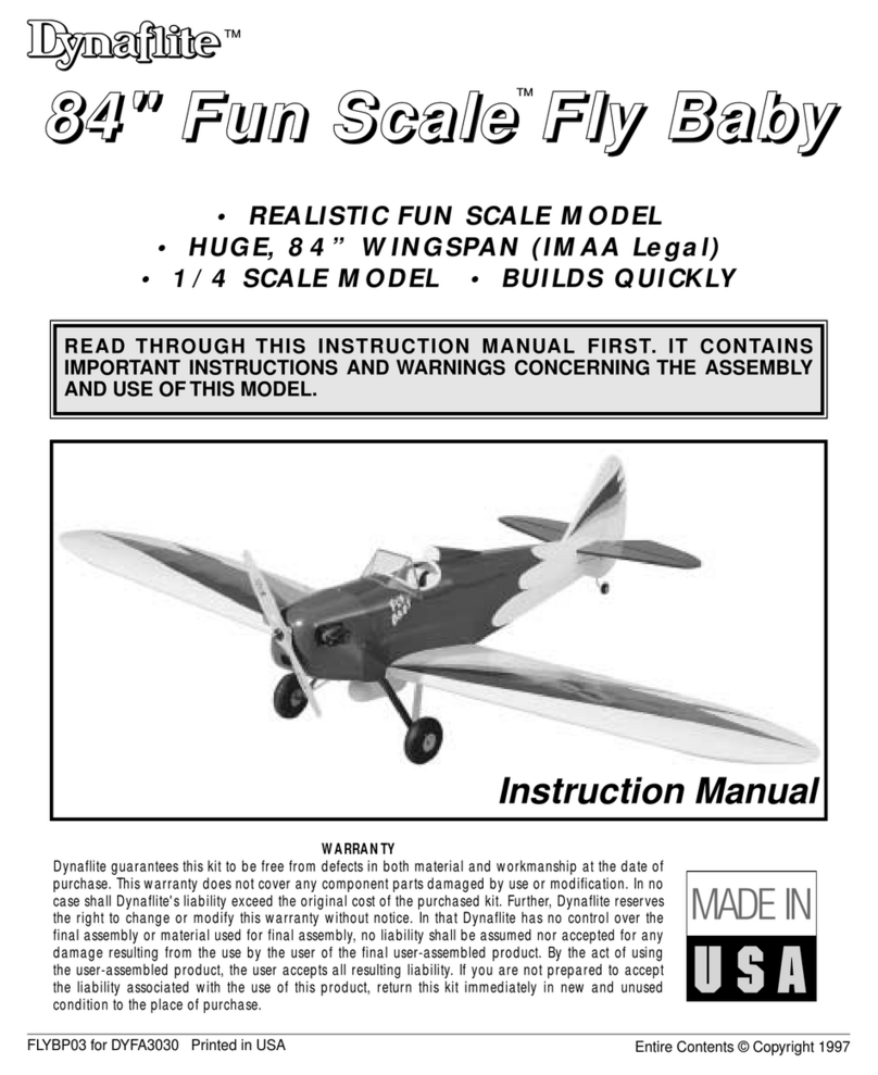
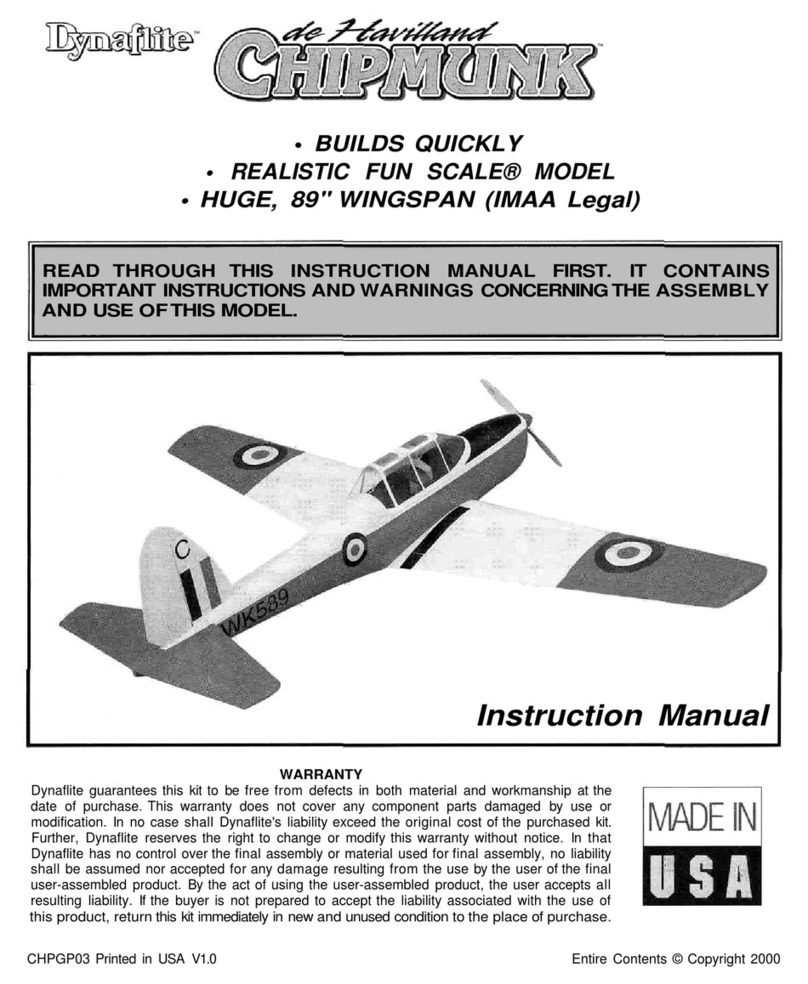
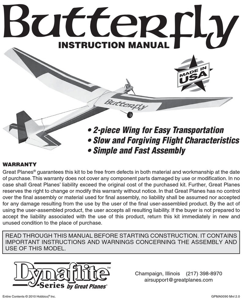
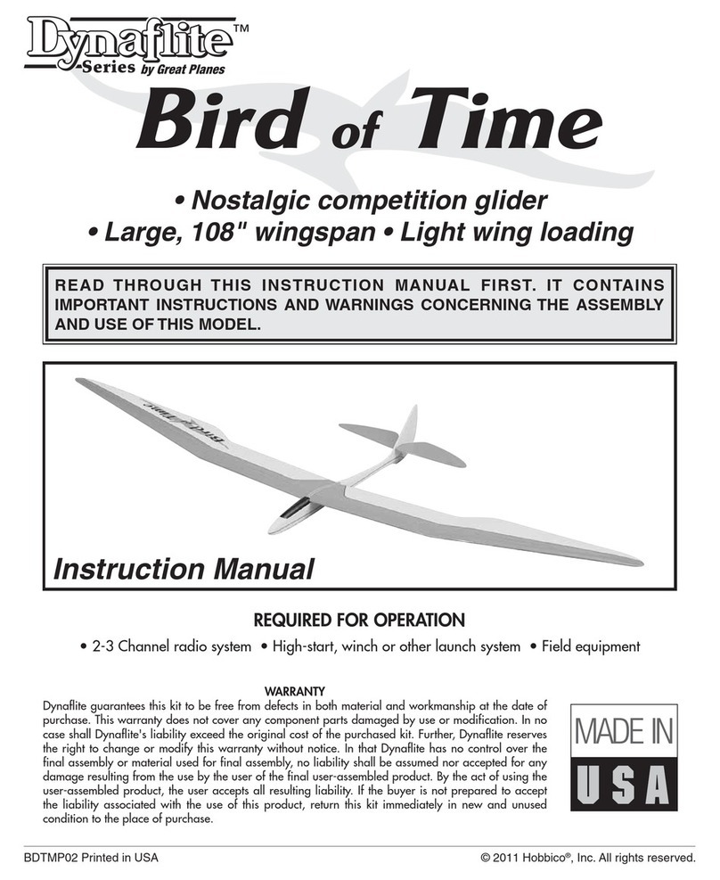
Dynaflite Daydream User manual

•Simple Entry Level Construction
•Stable Flight Characteristics
•Excellent R/C Trainer
READ THROUGH THIS INSTRUCTION MANUAL FIRST. ITCONTAINS
IMPORTANT INSTRUCTIONS AND WARNINGS CONCERNING THEASSEMBLY
AND USEOFTHISMODEL.
Instruction Manual
WARRANTY
Dynaflite guarantees this kitto befree fromdefects inboth material and workmanship at the
date of purchase. This warrantydoes not coverany component parts damagedbyuse or
modification.Inno caseshallDynaflite's liability exceed the originalcostof thepurchasedkit.
Further, Dynaflitereservesthe right tochangeor modify this warrantywithoutnotice. Inthat
Dynaflitehas no controlover the finalassemblyor materialused forfinalassembly, no liability
shallbe assumednor acceptedforany damageresultingfromthe use by the user of thefinal
user-assembledproduct. Bythe actof using the user-assembledproduct, theuser acceptsall
resulting liability.Ifthe buyer is not preparedto accept the liabilityassociatedwiththeuse of
this product, return this kitimmediately innew and unused condition to the place of purchase.
DDRMP03 Printed inUSA Entire Contents © Copyright 2000

Introduction
........................................................2
Precautions
........................................................2
Preparations...................................:...................3
Required Items..............................................................3
Suggested Building Supplies
......................................3
Optional Building Supplies
..........................................4
Building
Notes
....................................................4
Adhesives
......................................................................5
Glossary ofTerms Usedin
This
Manual
&
Plans
..........................................5
Die-Cut
Pattern
..................................................7
Build
the
Stabilizer
&
Elevator
..........................8
Build the Formers
........................................................8
Build
the
Fin
and Rudder
....................................9
Bevel the
Fin
&
Rudder
................................................9
Cutting
the
Hinge
Slots
..............................................10
Build
the
Fuselage
............................................10
Fuse
Side Construction
..............................................10
Fuse
Structure
Assembly............................................
11
Preparing the Canopy
................................................13
Build
the
Wing
..................................................14
Joining
the
Wing
Panels....................................17
Align
the
Stab
to
the
Wing
..............................18
Install
the
Forward Wing
Fillet..........................18
Balance
the
Model
Laterally
............................19
Finishing............................................................19
Final
Assembly
..................................................19
Radio
Installation..............................................20
Pushrod
Installation..........................................21
Final
Hookups
&
Checks
..................................22
Radio Settings
............................................................22
Balance
the
Model
............................................22
Checking
for
Warps
..........................................23
Preflight............................................................
24
Charge
the
Batteries
........................................24
Find
a
Safe
Place
to
Fly
....................................24
Range Check
the
Radio
....................................24
AMA
Safety
Code (excerpt)
..............................24
Flying................................................................25
Trim
Flights
......................................................25
Your First Hi-start Launch
................................25
First
Flights
......................................................26
Thermal
Flying
..................................................26
Facts
About
Thermals........................................27
Thermal Soaring................................................27
Pointers
for
Contest
Flying
..............................28
Slope
Soaring....................................................29
Flying
..........................................................................29
Slope Landings
..........................................................29
Ballasting..........................................................30
Flight
Log
............................................Back
Cover
Congratulations on your choice of this kitfor
yourproject. Ifyou arenew to Radio Control
Modeling, we would like to take a minuteto
give you some information on the Daydream.
The Daydream was designed to use a modern
airfoilspecificallydesigned forthermalgliders.
The constructionof the Daydream uses the
minimum amount ofmaterialsto keep the
overall weight down. The combination of these
provides you with a model that will beable to
catch and ride out the slightest thermal.
At Dynaflite we take pride inoffering kitsthat
are simple and straightforwardto build and
provide value for your modeling dollar.
Tomake your R/Cmodeling experience totally
enjoyable,we recommendthat you get
assistancewith yourfirstflightsfroman
experienced,knowledgeablemodeler.You'll
learnfasterand avoidrisk to your model before
you're trulyreadyto solo.Your localhobby
shop has informationabout flyingclubs inyour
areawhosemembership includes qualified
instructors.
You canalsocontactthe nationalAcademy of
ModelAeronautics(AMA),whichhasmorethan
2,500 charteredclubs acrossthe country. We
recommendyou jointhe AMA, which will
provide you with insurancecoverageat AMA
club sites and events. AMA Membership is
required at chartered club fields wherequalified
2
flightinstructorsareavailable.ContacttheAMA
at the address ortoll-free phonenumber below:
Academy of Model
Aeronautics
5151 EastMemorial Drive
Muncie, IN47302
(800) 435-9262
Fax (765) 741-0057
Internetaddress:
http://www.modelaircraft.org
parts are missing, broken or defective, or
ifyou have any questions about building
or flying this model, please call usat
(217) 398-8970 and we'll be glad to help.
Ifyou are calling for replacement parts,
please look upthe part numbers and have
them ready when calling.
You may also e-mail usat:
productsupport@dynaflite. corn
1.You must assemblethesailplaneaccordingto
the instructions. Do not alteror modify the
model,as doingso may result inan unsafe or
unflyablemodel. Ina few casesthe instructions
may differ slightlyfromthe photosor plan. In
those instances the text should be takenas
correct.
2.Youmusttaketimetobuildstraight,trueandstrong.
3.You mustinstallall R/Cand othercomponents
so that the model operatesproperly on the
ground and inthe air.
4.You must test the operation of the model
before thefirstand each successiveflight to
insure that allequipment operatescorrectly.
You must alsomakecertainthatthemodel has
remainedstructurallysound, especially after a
rough landing.
REQUIRED ITEMS
These are the itemsnot included with your
kit-you willneed to purchasethem separately.
Items inparentheses such as (GPMQ4243) are
suggested part numbers recognized bydistributors
and hobbyshopsandarelistedforyour
orderingconvenience.GPM istheGreatPlanes®
brand, TOP
is
the
Top
Flite®
brand,
HCA
is
the
Hobbico® brand and DYNis the Dynaflitebrand.
2- 4 ChannelRadio withtwo standard servos
Top FliteMonoKote® (approximately2 rolls)
1/4"LatexFoam Rubber Padding (HCAQ1050)
Switch and ChargeJack (GPMM1000)
2MeterUp-Start (DYNP8305) or Standard
Hi-Start(DYNP8301)
Note:We, as thekitmanufacturer,provideyou
witha qualitykitand great instructions,but
ultimately the quality and flyability of your
finishedmodeldepends on howyou assembled it;
therefore, we cannot inany way guarantee the
performance of your completed modeland no
representations are expressed orimpliedas to the
performance orsafety of your completedmodel.
SUGGESTEDBUILDING
SUPPLIES
We recommend Great Planes Pro CA and
Epoxy glue.
Please inventory and inspect allparts
carefully before starting to build.Ifany
2oz.ProCA(thin,GPMR6003)
2oz.ProCA+(medium,GPMR6009)
3

6-Minute Pro Epoxy (GPMR6045)
30-Minute Pro Epoxy (GPMR6047)
4oz. ProWood Glue (GPMR6161)
Hand or Electric Drill
SealingIron(TOPR2100)
Hobby Saw
HobbyKnife(HCAR0105)
#11Blades
Pliers(common and needle nose)
Screwdrivers (phillips)
T-pins(HCAQ5150)
60" RetractableTapeMeasure (HCAR0478)
Straightedgewith scale
MaskingTape (TOPR8018)
Sandpaper(coarse, medium,finegrit)
Easy-Touch'" Bar Sander (or similar)
PlanProtector(GPMR6167)
Lightweight Balsa Filler suchas Hobbico
HobbyLite'" (HCAR3400)
IsopropyI Rubbing Alcohol(70%)
Ballpoint Pen
90° Building Square
Heavy SewingThread (any color)
#64 Rubber Bands
Drill bits:1/16",5/64",3/32", 3/16",1/4"
OPTIONAL BUILDINGOPTIONAL BUILDING
SUPPLIES
CAApplicatorTips(HCAR3780)
EpoxyBrushes(GPMR8060)
Epoxy Mixing Sticks (GPMR8055)
CADebonder(GPMR6039)
HotSock" (TOPR2175)
Single-EdgeRazorBlades(HCAR0312)
Heat Gun (TOPR2000)
RazorPlane(MasterAirscrew®)
Great PlanesEasy-Touch Bar Sanders are
made fromlightweight extruded aluminum and
can be found atmosthobby shops. They are
availableinfive sizes - 5-1/2" (GPMR6169) for
thosetight,hardto reach spots; 11"
(GPMR6170) formost general purpose sanding;
and 22" (GPMR6172), 33" (GPMR6174) and 44"
(GPMR6176) forlong surfaces such as wing
leading edges. Easy-Touch Adhesive-Backed
Sandpaper comes in2" x 12' rolls of 80-grit
(GPMR6180), 150-grit (GPMR6183) and 220-grit
(GPMR6185) andan assortment of 5-1/2" long
strips (GPMR6189) for the short bar sander.The
adhesive-backedsandpaper iseasy to apply
and remove from your sanding bar when it's
time for replacement.
This setup isallthat isrequired for almost any
sandingtask.Custom sanding blocks can be
made frombalsaor hardwoodblocks and
dowels for sanding difficult to reachspots.
•When you see the term "test fit" inthe
instructions,itmeansyou shouldfirst
position the part on the assembly without
usingany glueand then slightly modify or
sand the part as necessary for the bestfit.
4

•Whenever the instructions tell you to glue
pieces together, thin CA should be used.
When a specific type of glue isrequired,
the instructions will state the typeof glue
thatishighlyrecommended.When30-minute
epoxy is specified, itis highly recommended
that you use only 30-minute (or slower)
epoxy because you will need either the
working time and/or the additional strength.
•Donotthrow away any leftover material
until afteryou have completed your model.
Some smallpieces of leftoverbalsa or
plywood areused during construction.
ADHESIVES
Thiskitisbuiltwith three types ofglue.
Cyanoacrylate - CA glues curealmostinstantly
and aremoderatelystrong. There arethree
common types used: thin, medium and thick.
Thin CA cures the fastestbut will not span gaps
between parts. Medium and thick CA areused
where parts do not fit perfectly. CA glue does
notbondwell to most plywoodsand
hardwoods. CA glues arealsobrittle. When
using CA glues we recommend keeping a bottle
ofCA debonder on your building table.
Aliphatic Resin - Resin glues require that
parts bepinned or clampedtogether while the
glue dries - typically 15to 30 minutes. Resin
glues are verystrong and workwell with balsa
and plywoods.
Epoxy - Six minute epoxy cures the fastest; it
sets within six minutes butis not fully cured for
one hour or more. Thirty minute epoxy is the
strongest as itallows the epoxy to soakinto the
wood thoroughly.While itsets within 30 minutes,
itis notfullycured for two or more hours.
Airfoil: A curved structure designed to create
liftbythereaction to air moving over itssurface.
C.G.(Center of Gravity): This is the point at
which the model balances forward and aft and
side-to-side.
Clevis: A small clip which isthreadedonto the
wireend of a pushrodandconnectsthe
pushrod to the control horn of a control surface.
The threadsallowfine adjustment of the
pushrods' length.
Control Horn:The arm which isattached to a
controlsurfaceat thehingelineandis
connected to a pushrod.
Die-cutParts: Precutparts stamped outof a
sheet of wood.The parts require a minimum of
preparation.
Dihedral: The V-shaped bend inthe wing.
Typically more dihedral causes more aerodynamic
stability inan airplane, and causesthe rudderto
controlboththe rolland yaw axis.
Doubler: Part of the structure that islaminated
to another part to increaseits strength.
Elevator:The hinged control surface located at
the trailingedge of the horizontal stabilizer,
which provides controlof the model about the
pitch axisand causes the model to climb or
dive. The correct direction of control isto pull
the transmitterelevatorcontrolstick back,
towardsthe bottom of the transmitter, to move
the elevator upward, which causes the airplane
to climb and vice versa to dive.
Foam Rubber:A soft foammaterial used to
wrapthe receiver and receiver battery for
protection.
5

Gusset:A brace used to reinforce the joint
between two parts.
High-start: A device used to launch a model
glider like a slingshot.This device consists of a
stake, an elastictube, monofilament line (or
string),a parachute or streameranda ring for
attaching the high-start to the glider.
Laminate: The process of gluing a multiple
numberof sheetsface-to-faceto increase
strength.
HorizontalStabilizer:The non-moving horizontal
tailsurfaceat theback of the fuselagewhich
provides aerodynamicpitch stability.
PitchAxis:The sailplaneaxis controlled by the
elevator. Pitch isillustrated by holding the
sailplane at each wingtip. Raising or lowering
the nose is the pitch movement.This ishow the
climb or dive iscontrolled.
Pushrod:A rigid piece of steel, plastic or wood
used to transfermovement froma servo to a
controlsurface.
Receiver (RX):Theradio unit inthesailplane
which receives thetransmitter signaland relays
the controlto the servos. This is somewhat
similartothe radio you may have inyourfamily
automobile,excepttheradioin theglider
perceivescommands fromthe transmitterand
the radio inyour carperceives music fromthe
radio station.
Rudder: Hinged controlsurfacelocatedat the
trailingedgeof the verticalstabilizer,which
provides controlof the sailplaneabout the yaw
axis and causes the sailplaneto yaw left or
right. Left rudder movement causes the sailplane
to yaw left and right rudder movement causes it
to yaw right.
Sailplane:Anairplane which flies without an
engine. Sailplanesaredesigned to ride on
warm, rising air currents, calledthermals.
Sailplanes are launched by several methods: a
giant sling shot called a high-start or a winch
which pulls the sailplaneuplike a kite.
Servo: The electronic/mechanical device which
moves the control surfacesof the sailplane
accordingto the commandsfromthereceiver.
The radio device which does the physical work
inside the sailplane.
Servo Arm:The removable arm or wheel which
bolts to the output shaft of a servo and connects
to the pushrod.
Tow Hook: A device used to connect thetow
line to the sailplane during launch.
Transmitter:The hand-held radio controller.
This isthe unit that sends out the commands
that you input.
Vertical Stabilizer: The non-moving surface
that is perpendicular to the horizontal stabilizer,
often referred to as the fin, providing lateral
stability.The rudder attaches to this surface.
Wing:The main lifting surfaceof an airplane.
Yaw Axis: The glider axis controlled by the
rudder. Yaw isillustratedby hanging the glider
level by a wirelocatedat the center of gravity.
Left or right movement of the nose isthe yaw
movement. Many glidersarenot equipped with
aileronsandthe roll andyawaxisarecontrolled
by therudder. This isdue to the largeramount
of dihedralinthe wingandiswhy most
sailplaneshave a large amount of dihedral.
6

7
Die-CutPattern

BUILDTHEFORMERS
Q1.Unrolltheplan.Re-roll the planinsideout
to make itlieflat. Wax paper or Great Planes
Plan Protector" placed over the plan will
prevent glue fromsticking to the plan.
Q2.Place the 3/16" x 1"x 14"balsa stick over
the portion of the plan marked leadingedge
joiner, andline up the back edge of the stick
with thestraightline. Draw two angled lines
whereyou will cut this stick. There aretwo
dashed lines on the plan to help indrawingthe
lines inthe correct location.Remove the stick
from the plan and cut the stick along the lines
usinga hobby knifeor razorsaw. Straighten
and square the cut edges with a sanding block.
Trim the ends slightly to match the length
shownon the plan.
Q3.Pinthe stab forward center intoposition on
the plan. Test fit the 3/16" x 2" x 3" balsa stab
center into place.There shouldbe no gaps
between the center and forwardpieces. After
fitting, pin and glue the center to the forward
using medium CA.
Q4.Use two 3/16" x 3/8" x 36" balsa sticks to
build the outside framework of the stabilizer.
Start bycutting and placing the longest piece
first,working until you are placing the shortest
(end)pieces. Glue each piece together using
medium CA as you proceed.
BUILDING HINT:
Ifyou are unfamiliar with "Built-up"
construction,we have found that the
following method isvery easy and accurate.
A. Position an uncutstick directly over the
planand pinitinplace.
B.Mark each side of the stick where itends
or butts with another part.
C.Remove the stick fromthe building
surfaceand flip itover. Draw a line
between the marks you made previously
using a straightedge.
D.Using a razor saw, cutas close to the line
as possible. Then, with your sanding block,
true-up the ends to the line. Flipthe part
over andpin back inplace over the plan.
05.Cut and installthe stab bracing using a
3/16" x 3/16" x 36" balsastick. Note: Itisbest to
start with the straightpieces, then go to the
angled pieces. The alignment ofeach piece to
the plan isnot critical, justas long as itisclose
and fitssnugly into position. Use theremaining
wood from the stab forward center for the
gussets inthe corners.
8

Q6.Remove the stabilizer from your building
surface. Examine and add thick CA glue to any
open joints, then use your sanding block with
medium (150-grit)sandpaper to sand both
sides of the stabilizerframeworksmooth.
Q3.Remove the rudder from your building
surface. Examine and add thick CA glue to any
open joints,then use your sanding block or bar
sander with medium (150-grit)sandpaper to
sandboth sides of the rudder smooth.
Q7 Build the elevatorfromthe 3/16" x 3/16" x 36"
balsasticksand the 3/16"x 3/8" x 36" balsa sticks.
BUILDTHEFIN& RUDDER
Ql1.Position the plan on yourworksurfaceso
the rudder andfin can be built directlyon the
plan.Wax paperorGreatPlanesPlan
Protector placedover the plan will prevent
glue fromsticking to theplan. Build theoutside
frameof the rudder using the 3/16" x 3/8" x 36"
balsa stick. Cut andinstallthe cornergusset
from the remaining 3/16"x 3/8" balsa.
Q2.Build the inner frameworkof the rudder
using 3/16" x 3/8"x 36" and 3/16"x 3/16" x 36"
balsa sticks.
Q4.Build the fin fromtheremaining3/16" x
3/8" x 36" and 3/16" x 3/16" x 36" balsa sticks.
Examineand add thick CA glue to any open
joints,then use your sanding block or bar
sanderwith medium (150-grit)sandpaper to
sandboth sides of the fin smooth.
Q5. Place the fin and rudder flat on your work
surfaceand sand them flatusing a sanding
block or bar sander and150-grit sandpaper.
Don't forgetto sand both sides smooth.
BEVELTHE FIN& RUDDER
Q1.Referring to the cross-sections on the plan,
carefullyblock sand the elevatorand rudder
leading edges to the shape shown on the plan.
Q2. Using 180-grit sandpaper, round the leading
edge andtips of both'thefin and stabilizer.
Leave the trailingedges square. Round the
trailingedges and tips of the rudderand
elevatoras shown on the plan using 180-grit-
sandpaper.
9

CUTTINGTHEHINGESLOTS
Q1.Lay the rudderand elevator on the plan
sheet and mark the hinge locations. Place the
rudder against the finTE and transferthe marks
over to the fin. Place the elevatoragainst the
stabTE and transferthe markson to the stab.
I..12. Tocutthe slots for thehinges, usethe
following steps:
A.Begin by carefully cutting a very shallow
siitat the hinge position on the centerline.This
first cut isto establishyour cut inthe right
place, so concentrateon stayingon the
centerline and don't cut too deep!
QlB.Make three or four more cuts inthe same
line,going slightly deeper each time. As you
make these additional cuts, work on going
straight into the wood. Continue the process
while "wiggling" the knife handle forwardand
backward until the blade has reached the proper
depth forthe hinges.
1-.1C.Test fit the hinge into theslot. Ifthe hinge
isdifficult to push in,re-insert the knife and
move itback and forth inthe slot a fewtimes to
enlarge the slot.
Q3.Insert the hinges into the slots and test fit
the rudder andelevatorto the fin and stabilizer.
Donot glue the hingesuntilafter you have
covered the model.
Q2. Use two ofthe 1/8"x 1/4"x 24" balsa sticks
to make the upper and lower fuse rails. Use
medium CA to glue them into position.Trim the
excess extending past the stabilizer base.
Q3.Once the glue sets, remove the fuse side
from your building surface.Examineand add
thick CA glue to any open joints,thenuse your
sanding block or bar sander with medium (150-
grit)sandpaper to sand both sides of the
fuselage side smooth.
Ql4. Repeat steps 1 through 3 to build another
fuse side.
FUSESIDECONSTRUCTION
Q1.Locate the die-cut 1/8"balsa stabilizer
bases and fuse sides. Drill two 1/4" holes in
the fuselagesides at the punch marks. Pin one
side andone base over their appropriate
locations on the plan.
QQ 5.Select fourof the hardest 1/16"x 3" x
24" balsa sheets to be used forthe fuse sides.
Cut a 45° on oneof the 1/16" x 3" x 24" sheets.
Use a straightedgeto true up thelonger edge of
the sheet. Align the bottom fuse rail with the
10

trued edge. Apply medium CA to the fuseside
where the sheet will contact it.Place the sheet
onto the fuse side.
FUSESTRUCTURE
ASSEMBLY
QQ 6.From another1/16"x 3" x 24" balsa
sheet, trim an angleon an end closeto 45°,but
notquite. Test fit the piece against the first,and
make sure the sheet fully covers the forward
fuse side. Glue the sheet to the fuse side using
mediumCA.
Q1.Test fitthe die-cut 1/8" ply former F2in
place on the rightfuse side. Position the tab
on the formerso itfacesthe bottom of the
fuselage.Press itdown into its slot and use a
90° triangleto keep itperpendicularto the fuse
side.Glue itinplace with medium CA.
QQ7.Trim the excess sheeting fromaround the
fuse side. Drill the 1/4"holes made in the
fuselagesides through the 1/16" sheeting. Use
150-grit sandpaperto sandthe sheeting flush
with the edges of the fuseside. Use your
sanding block or bar sanderwith medium (150-
grit) sandpaper to sand the sheeting smooth.
Q2.Test fitthe die-cut 1/8" ply former F3in
placeon the rightfuseside. Press itdown into
its slotanduse a 90° triangleto keep it
perpendicular to the fuse side. Glue itin place
with medium CA.
Q8.Repeat steps 5 through 7 forthe remaining
fuse side. Make sure to make both a left
andrightside.
Q3.Position the left fuselage side onto the
formers.Use medium CA andglue the fuseside
to the formers.
Q4.Tape a piece of waxpaper or Plan Protector
over the fuselagetop view on the plan.
Q5.Test fit the die-cut 1/8"ply former F1in
placeat the frontof the fusesides. After
checking the alignment of the fuselageto the
plan, glue formerF1to the fuse sides using
mediumCA.
11

I-]6.Locate the die-cut 1/8" ply forward fuse
bottom. Place the forwardfusebottom onto
the fuselage.Set the fuselageassembly upright
(in its normal position) on the waxedpaper.
With everything inits proper place, apply thin
CA glue to allthe joints,aroundthe formersand
along the bottom. Keep checking the parts fit
and alignment as you glue. Wait a minute for
the glue to set, then apply thick CA to the joints
to make sure a good bond exists, especiallyin
the joints that do not fit perfectly. Note:The use
of CA acceleratorwill be helpful when using
thick CA to fillany large gaps.
Q9.Cut two 7" long pieces from the 3/16" x
3/16"x 24" balsa stick. Glue the pieces to the
upper inside edge of the fuselage infront of F2
using medium CA.
Q10.Once the glue sets, use your sanding
block or bar sander with medium (150-grit)
sandpaper to sand the sticks smooth.
Q11.From the 3/32" x 3" x 36" balsasheet, cut
and glue pieces of cross-grain sheeting to the
topof thefusefromF1to F2. Savethe
remaining sheet fortheaft top of the fuselage.
Qi7.Pull the fusesides togetherat the tailend
of the fuselage.Use a T-pin to pin the sides
together and check the alignment. Once the
alignment iscorrect, use thin CA to glue the
very aft edge together.
Q8. Place the die-cut 1/8" ply former F4into
positionusingtheplanto determineits
position. Whileholding the sides against F4,use
medium CA to secure the formerto the sides.
Q12.Use a piece of 3/32" x 3" x 24" balsato
sheet the bottom of the fuselagefromthe aft
edge of the ply fuse bottom to theend of the
fuse. Use theplan to keep the alignment of the
fuselagewhilesheeting.Once the glue sets, trim
the excess sheetfromtheedges of the fuselage
using a hobby knife. Use yoursandingblock or
bar sanderwith medium (150-grit)sandpaperto
sandthe sheet smoothwith the sides.
12

Q13.Use medium CA to glue twopieces of
3/16"x 3/16"balsastickinto thecorners
between the fusebottom andthe fuse side
between formersF2 and F3.Use medium CA to
glue two more pieces of 3/16" x 3/16" balsastick
between formersF2 andF3alongthe upper
edge of the wing saddleas shown on theplan
side view.
Q14.Use medium CA to glue the 1-3/4"x 1-3/4"
x1-1/2" balsa nose block onto the frontof the
fuselage.
Q15.From the remaining piece of 3/32" x 3"x
36" balsa,sheet the top of thefuselagefrom
formerF3to thefrontof thestab saddle.Thisis
one piece of sheeting, with thegrainrunning
from the frontto therear of thefuse.Once the
glue sets, trim the excesssheet fromthe edges
of the fuselageusing a hobby knife.Use your
sanding block or bar sanderwith medium (150-
grit)sandpaperto sandthesheet even with
the sides.
sandpaper, round the corners of the fuselage to
the shape shown on the cross-sections of the
formers on the plan. Shape the nose block to
the shape as shown on the plan.
PREPARING THECANOPY
Q1.Draw the outline of the canopyonto the
fuselageusing the plan as a guide. Use a hobby
knife and/or razor saw to carefully cut the
canopy from the fuselage.
Q2.Use yoursandingblock or bar sanderwith
medium (150-grit)sandpaperto sandthe edges
of thecanopyandfuselagesmooth.Use
caution not to remove an excess amount of
material, or the fitbetween the canopy and
fuselagewillbe loose.
Q16.Using a razorplane andyoursanding
block or bar sander with medium (150-grit)
3. From the remaining 3/16" x 3/16" balsa,cut
two 3/4" pieces which willextend 1/4"to 1/2"
forwardof the canopy to act as locking pins.
13

Note: The Daydream wing, muchlikethe
fuselage, isdesigned with simplicity and ease
of building inmind. Always remember to test fit
parts beforeusing glue to make any
adjustments for the best possible fit.
QQ 1.Cutthe"rightwing panel" section
from the plan and tape iton your building
board. Tape a piece of wax paper or Plan
Protector over the plan.
QLJ2.Locate one of the 1/16" x 3" x 24" balsa
leading edge sheets. Use a straightedgeto
true up one edge of the sheet. Align the end of
the sheet with the outer R2 wingrib,and the aft
edge of the sheet alongthe aft edge of the spar.
Pinthe sheet intoposition.
QQ 3.Locate one of the1/8"x 3/8" x 24"
basswood spars. Usingthe spar locationfrom
the plan, glue the spar to the sheet using
medium CA.
QQ 4.Pinone of the 1/16"x 1-1/4"x 24" balsa
trailing edge sheets inits proper location.
Mark the positions of the R1 Ribs on boththe
trailing edge sheet and the spar.
QlQ 5.Add the center sheeting between the
trailing edge sheeting and sparusing 1/16" x 3"
x24" balsa. The sheeting islocated only under
the R1 Ribs.
QQ 6.Remove the die-cut 1/16" balsawing
ribs R1 andR2 fromthe die-cut sheets. Slide
thewing ribs into position on the bottom spar.
QQ17. Use the die-cut 1/8"ply dihedral gauge
to set the angle of the root rib. Use thin CA to
glue the R1 and R2 ribs to the sparand trailing
edge sheeting. Note:Donotglue the ribs to the
leading edge sheeting at this time.
QQ 8.Locate anotherof the 1/8" x 3/8" x 24"
basswood spars. Glue the spar intothe top rib
notches using medium CA.
QQ 9. Trim a piece of 1/16" x 3" x 24" balsa
sheet to a width of 2-5/16".Use this sheet to
make the shear webs. With the panelheld flat
on the table, use medium CA to glue the balsa
shear webs to the spars, between allthe ribs
infront of the spars. Notice thereareshear
webs on both sides of the sparsbetween the
R1 ribs andonly infront of the sparsbetween
the remainder of the ribs.
Note:
The
function of the shear webs isto keep
the
spars
from
collapsing.They
will
not need
to
14

touch or begluedto theribs.Theyshouldbe
thoroughly glued to the spars.
QQ 10.Remove the pins holdingthe wing
panel to yourbuilding surface.Slowly lift the
trailingedge up off the plan, rollingthe wing
onto the frontpart of the wing ribs. The rolling
process isto push the sheeting against the wing
ribs, allowingyou to glue the sheeting to the
ribs using thin CA.
QQ11.Once the glue sets, alignthe wing panel
back onto the plan. Use medium CA to glue a
1/16" x 1-1/4" x 24" balsatop trailingedge sheet
into position. Glue a 1/16" x 3" x 24" balsa top
leadingedge sheet onto the sparand the front
area of the wing ribs.
QQ 12.Sheet the center-section area between
thetrailingedge sheeting and spar using 1/16"
x3" x 24" balsasheeting.
ahobby knife or razor saw. Useyour sanding
block or bar sander with medium (150-grit)
sandpaper to sand the sheeting and the leading
edges smooth.
14.Using a Hobby Knife, remove the
section of the tip R2 rib between the spars.
QQ15.Place the center panel onto the plan
aligningthe R2 rib to the plan. Block the pane
upso the center is3" fromthe building surface
QQ13.Remove the center panel from the plan.
Cut the sheeting and the leading edges flush
with the outer edges of the R1 and R2 ribs using
QQ16.
Place
a
1/8"
x 3/8" x
24"
balsa
spar
over
its
location
on the plan and cut
it
to
length.
Using
the criss-crosspin technique shown inthe
illustrationto pin the sparin3 or 4 places. The
end of the sparmust be sanded to fit tightly
againstthe spar on the center panel.
QQ17.Insert the narrow end ofthe die-cut 1/8
ply tip dihedral brace into the opening which
you previouslycut between the sparsinthe
center wing panel. Donotglue the brace a
this time.
QQ18.Pinone of the 1/16"x 1-1/4"x 24" balsa
trailing edge sheets inits proper location.
15

QQ 19.Remove the die-cut 1/16" balsawing
ribs R3throughR10 fromthe die-cut sheets.
Slidethewing ribs into positionon the
bottom spar Glue the wing ribs to the spar
and TE sheeting using medium CA. Glue the
R3A and R3B wingribs to the R2 rib of the
center panel using medium CA.
QQ 20. Use thin CA to glue the tip dihedral
brace to the sparsin both the center and tip
wing panels. Use medium CA to fillany gaps
between the sparand dihedral brace.Thismust
bea very strong glue joint.
on the table, use medium CA to glue the balsa
shearwebs to the front and backof the spars,
between the R3 and R4 ribs, and to the front of
the sparsfromR4to R8.
QQ 24. Cut a 1/4"x 1/2" x 24" balsa leading
edge to length forthe center panel. Alignthe
bottom of the leading edge to the bottom of the
wingsheeting. Use medium CA to gluethe
leading edge to the ribs and sheeting on center
panel.Cut another 1/4"x 1/2"x 24"balsa
leading edge tolength, allowingitto extend1"
pastthe wingtiprib R10. Sandthe end ofthe LE
so itfits againstthe LEon the centerpanel
without anygaps. Alignthe LE to the bottom of
the ribs on the outer panel and glue itinto
position using medium CA.
QQ 25. Cut both of the wing tips using a 3/32"
x3" x 24" balsa sheet.
Qt-l21.Locate another of the 1/8" x 3/8" x 24"
balsaspars.Cut thesparto length. Glue the
spar into the top rib notches using medium CA.
Q0 22.Trim a 1/16"x 1-1/4"x 24" balsa trailing
edge sheet to length. Use medium CA to glue
the sheet into position on the top of the ribs.
QQ 23. Trima piece of 1/16"x 3" x 24" balsa
sheet to a width of 2-5/16". Use this sheet to
make the shear webs. With the panelheld flat
QLI26. Use medium CA to gluethe wing tip
into position. The wing tip is alignedwith the
bottom of the wing. Add the bracingusing the
remaining 3/32" x 3" x 24" balsa sheet.
QQ 27.From the remaining 3/32" x 3" x 24"
balsa sheet, make the gussets forthe wing tip
panels. Using the plan as a guide, glue the
gussets into place using medium CA.
16

Q2.Use a flatblade screwdriverto knock outthe
center of the second R1 ribs between the spars.
Q3. Locate and gluethe two die-cut 1/8" ply
center dihedral braces togetherusing
medium CA or 6-minute epoxy.
Note: Inpreparation for the next step, protect
your work surfacebycovering itwith waxed
paper orPlan Protector.
QQ 28. Use a razorplaneandmedium (150-
grit) sandpaper to sand the leading edge to
shape. Use the die-cut LEgauges to check the
shape of the leadingedge as you work. Sand
the tip sectionLEto match the die-cut 1/8" balsa
tipLEgauge, and the center-sectionLEto
match the die-cut 1/8" ply center LEgauge.
Q29. Repeat steps 1 through 28 to buiid the left
wing panel.
Q1.Remove the materialfromR1 between the
spars using a hobby knife.
Q4.Test fit the center dihedralbrace into each
wing panel. Make any adjustmentsnecessaryto
allowthe wing panelsto slide completely
17

togetherwiththe braceinstalled.Oncethe
brace fits, use 30-minute epoxy to liberally
cover the brace and the two R1 ribs. Also coat
the spars inside the wing by applying epoxy
with a stick.There should be enough epoxy that
itwill "ooze" out of the center of the wing
panels. This excessepoxy canbecleanedup
using a paper toweland isopropyi alcohol.Use
masking tapeto hold the two panels together
untilthe epoxy has cured.
Note:The correctamount of dihedral between
the two center panels can be measured by
placingone center panel flaton thework
surface.Theother center panel, when measured
where itattaches to the tip panel, will measure
about3" fromthe work surface.This measurement
isnot critical,and can varyup to 1/4" either
direction without causing any flight performance
problems.
Q5.Once the epoxy has fully cured,use 150-
grit sandpaper to sand the joint between the
two panels smooth.
Q6.Cuttwo scraps of 1/8"plywood to beused
as a trailingedge support. This willprevent the
rubber bands fromcrushingthe trailingedge of
the wing. Use the plan as a guide forcutting
and positioning the support.
Q2.Temporarilyinstallthe two 3-1/2"wing hold
down dowels inthe fuselage.Set thewing on
the fuselageandsecureitby hookinga couple
of rubber bands (notincluded) over the forward
dowel, stretching the rubber bands over the
wing andhooking them over the aftdowel. Set
thestabilizerin the stabilizersaddle.Check the
alignment of the stabilizerwith the wing from
the front and rear of the model. Ifthe stabilizer
tipsarenot equidistantabovethewing,
carefullysand the high side of the stabilizer
saddleuntil the stabilizerandwing arealigned.
Use a tape measureto set the stabilizer tips
equal distances from the nose.
Q3.UseT-pins to hold the stabilizerinposition
on the fuselagewhilemarkingthebottom of the
stabilizer where itmeets the fuselage.Donot
glue itinposition at this time.
LJ1.With the fuse placed right side up on a flat
surface, test fitthe wing into the wing saddle.If
the wing isslightly too large(frontto rear)to fit
into the wing saddle, sand the rear edge of the
saddle and the wing trailing edge slightly until
itfits.
Q1.Carve and sand the 1/2"x 2" x 2-1/2" balsa
front wing fairing to fit the top of the wing.
Round the cornersof the block to match the
fuselage.
Note:Itisdifficult (and not necessary) to try to
carve this block to mate exactly with the wing;
therefore,you should just"roughitout,"then
later you can fillany gaps with balsa filler.
18

Donotconfuse thisprocedure with "checking
theC.G."Thatwill bediscussed laterinthemanual.
Now that the model isnearly completed, you
should balanceitlaterally(side-to-side). An
airplanethat is laterallybalanced will track
better. Here's how:
Q1.Temporarily attach the stabilizer, elevators,
fin, rudder and wing. Lift the model by the nose
and the bottom ofthe fusenear the rudder.This
will require an assistant. Dothis several times.
Q2. The wing that consistently drops indicates
the heavy side. Balance the model byadding
weight to the other wing tip.
Make sure that allthe surfaces to becovered
have been sanded to remove any irregularities.
The DynafliteDaydream can be coveredwith
Top Flite MonoKote® or EconoKote"film, using
the suggested covering sequence that follows."
Suggested Covering Sequence
Fuselage andTail:
1.Fuselage bottom
2.Fuselagerightside
3.Fuselage left side
4.Fuselage top
5.FinTE, followedby the fin sides
6.StabilizerTE, followedbythe bottom andtop
(onlycover the bottom ofthe stabilizer
upto the marks where the fuselage
meets the stabilizer)
7.Elevator LEand root ends
8.Elevator bottoms, followed bythe top
9.
Rudder
LE,
right side followed bythe left
sid»
10.Hatch
Wing:
Tack the covering to the wing tips and leading
and trailingedges. Donot shrink the covering
untilafter the wing iscompletely covered.
1.Tipsofwing
2.Trailing edges of wing
3.Bottom of both wing halves
4.Top of both wing root halves (extend the
covering 1/4"past rib W-4 and tack itto the
outboardfaceof the rib)
5.Top of both wing tip halves
Afterthewing iscompletelycovered,shrinkthe
covering on the bottom ofthewing, keepingthe
wingas straight as possible. Next, place the
wing
root panel against
a
flat
building
surface
while shrinking the top covering.
Once the root panels are done, place a tip panel
on
a
flat surface. While holding the
wing
firmly
against the flat surface, shrink the top covering
Thiswill prevent any "washout" inthe tip panels
After all the covering on the wing has bee
shrunk, and you have double-checked the
bottom
panels, iron the covering to each wing rib.
Q
1.
Center
and glue the
two
3-3/4"
wing
hold
down dowels inthe fuselage.
Q2.Setthe wing on the fuselage and secure
to the fuselagebyhooking a couple of #6
rubber bands (not included) over the forward
dowel, stretching the rubber bands over the
wing and hooking them over the aft dowel
Again, set the stabilizerinthe stabilizersaddle
Check the alignment of the stabilizerwith the
wing fromthe front and rear of the model.
Use
19

atape measure to setthe stabilizer tips equal
distance from the nose.
Q3.Use 30-minute epoxy to glue the stabilizer
inposition on the fuselage,rechecking the
alignment before the epoxy cures.
Q4.Remove the covering from the bottom of
the fin. Test fit the fin onto the stabilizer. The
trailing edge of the finshould align with the
trailingedge of the stabilizer. When satisfied
with the fit, glue the finto the stabilizerwith
6-minute epoxy or aliphaticresin. Make sure
the finis90° to the stabilizer.Maskingtapeand
T-pins can beused to holditinplace.
Q5.Starting withthe elevators and stab, cut
the covering from the hinge slots.
The most common mistakemade by modelers
when installing a CA type of hinge isnot
applyinga sufficient amount of glue to fully
secure the hinge over itsentire surfacearea; or,
the hinge slots are very tight, restricting the
flow of CA to the back of the hinges.This results
inhingesthatare only "tack glued"
approximately1/8"to 1/4"into the hinge slots.
The followingtechnique has been developed to
help ensure thorough and secure gluing.
D6.Itis best to leave a very slight hinge gap,
ratherthan closing itup tight, to help prevent
the CA fromwickingalongthehinge line. Make
sure the
control
surfaces
will
deflect
to
the
recommended throwswithout binding. Ifyou
have cut your hinge slotstoo deep, thehinges
may slideintoo far, leaving only a smallportion
of thehinge inthe controlsurface.To avoid this,
you may insert a smallpin throughthe center of
each
hinge beforeinstalling.This
pin
will
keep
the hinge centered while you install the control
surfaces.
I—17.Install the hinges inthe elevator and attach
the elevatorto the stabilizer.
Q8.Apply 6 drops of thinCA adhesiveto both
sides of each hinge. Allowa few seconds
between drops for the CA to wick into the slot.
Q9.Follow the same procedure to installthe
rudder on the fin.
Q10.Reinstall the control horns.
Q11.UseaT-pin inserted through the tow hook
block from the inside of the fuselageto locate
the towhook pilot holes.Threada 4-40 nut onto
the tow hook. Then, thread the tow hook into
the tow hook block fromthe bottom of the
fuselage to the depth shown on the plan.
Ql1.From the remaining3/16"x 3/8" basswood
spar, cut threeservo rails. The railsshouldbe
snug againstthe fuselagesides, but not so tight
thatthey cause the fuselage sides to bow
outward.
QQ 2. Slide thefirstservorailinto its slotinthe
fuselagedoubler. Slideitallthe way forward
and glue itinplace with thick CA. Slidethe
secondservo railinto placeandthenslideitall
the way aft.Donot glue ityet! Position one
ofyour servosinplaceanduse itto position the
second servorail.Donot push the rearservo
railtight againsttheservo, but ratherleave
abouta 3/32" gap between the.servo"body"
and the servorail.This willprovide enough
room to installand remove the servos without
removing the rails.Gluethe secondservo rail in
place.Repeat the step forthe second servo to
position and glue the third servo rail.
20
Table of contents
Other Dynaflite Toy manuals

Dynaflite
Dynaflite Skeeter User manual

Dynaflite
Dynaflite butterfly User manual

Dynaflite
Dynaflite CHIPMUNK User manual

Dynaflite
Dynaflite Bird of Time User manual

Dynaflite
Dynaflite Talon User manual

Dynaflite
Dynaflite Wanderer User manual

Dynaflite
Dynaflite Bird of Time User manual

Dynaflite
Dynaflite DYFA3030 User manual

Dynaflite
Dynaflite super decathlon User manual

Dynaflite
Dynaflite PT-19 User manual