manuals.online logo
Brands
  1. Home
  2. •
  3. Brands
  4. •
  5. Giant
  6. •
  7. Water Pump
  8. •
  9. Giant P532 User manual

Giant P532 User manual

Contents:
Performance Information: page 2
Installation Instructions: page 3
Exploded View: page 4
Parts List/Kits/Torque Specications: page 5
Repair Instructions: page 6
Trouble Shooting Chart: page 7
Recommended Spare Parts List: page 7
Dimensions: back page
Warranty Information: back page
Models
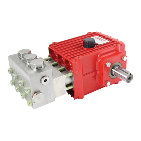
P532, P533 and P536
Triplex Ceramic
Plunger Pump
Operating Instructions/
Repair and Service Manual
Updated 04/23
2
U.S. ............................................(Metric)
Temperature of Pumped Fluids ............................Up to 104 oF .........................(40 oC)
Inlet Ports............................................................................................................2 x 1” BSP
Discharge Ports ..................................................................................................2 x 3/4” BSP
Shaft Rotation .....................................................................................................Top of pulley towards manifold
Crankshaft Diameter ............................................1.18” ......................................(30 mm)
Key Width.............................................................0.315” ....................................(8 mm)
Shaft Mounting....................................................................................................Either side (specify when ordering)
Weight ..................................................................64 lbs ....................................(29 kg)
CrankcaseCapacity..............................................54 .oz. .................................(1.6 liters)
NPSHR (at ambient temperature)........................26.9 ft. head ..........................(8.2 mWs)
1. Performance
P532/P533/P536
*Requires 15 PSI inlet pressure
Max. Flow Pressure Max. Speed Power Req’d.
Plunger
Diameter Stroke
Model GPM PSI RPM BHP In. In.
P533 22.7 2175 1450 34.1 1.26 1.02
P532 24.4 2175 1450*36.6 1.26 1.10
P536 26.4 1740 1450 31.6 1.42 0.945
Max. Flow Pressure Max. Speed Power Req’d.
Plunger
Diameter Stroke
Model LPM Bar RPM kW mm mm
P533 86.0 150 1450 25.4 32 26
P532 92.5 150 1450*27.3 32 28
P536 100 120 1450 23.6 36 24
U.S. Measurements
Metric Measurements
Common Specications
In order to drive the pump from the side opposite the
present shaft extension, simply remove the valve casing
from the crankcase and rotate the pumps 180 degrees to
the desired position. Be certain to rotate the seal case
(item #20) as well, so that the weep holes are down at the
six o’clock position. Exchange the oil ll and the oil drain
plugs, also. Refer to the repair instructions as necessary
for the proper assembly sequence.
SPECIAL NOTE:
P532-
The theoretical gallons per revolution (gal/rev) is
0.0168. To nd specic outputs at various RPM, use
the formula: GPM = 0.0168 x RPM
P533-
The theoretical gallons per revolution (gal/rev) is
0.0157. To nd specic outputs at various RPM, use
the formula: GPM = 0.0157 x RPM
P536-
The theoretical gallons per revolution (gal/rev) is
0.0182. To nd specic outputs at various RPM, use
the formula: GPM = 0.0182 x RPM
Materials Used:
Valve Casing:.................Special Brass
Plungers: .......................Solid Ceramic
Valves: ...........................High Grade Stainless Steel
Seals:.............................Nitrile with Fabric Reinforcing
Crankshaft: ....................Drop Forged and case-hardenend
3
1.3 Horsepower Information
Horsepower ratings shown are the power requirements for the pump. Gas engine power outputs must be
approximately twice the pump power requirements shown above.
We recommend that a 1.15 service factor be specied when selecting an electric motor as the power source.
To compute specic pump horsepower requirements, use the following formula:
(GPM X PSI) / 1450 = HP
1.2 Pulley Information
Pulley selection and pump speed are based on a 1725 RPM motor and “B” section belts. When selecting
desired GPM, allow for a ±5% tolerance on pumps output due to variations in pulleys, belts and motors
among manufacturers.
1. Select GPM required, then select appropriate motor and pump pulley from the same line.
2. The desired pressure is achieved by selecting the correct nozzle size that corresponds with the
pump GPM.
Performance data for intermittent operation, data for continuous operation on request.
For information on intermittent operation and calculating of the performance data, see the Giant Pumps
assembly instructions.
NPSHR / Inlet pressure
Required NPSH refers to water at 60 °F (20 °C) at max. permissible pump speed.
Maximum inlet pressure: 29 PSI (2 bar)
Level of noise emission
Emission sound pressure level: ≤ 85 dB(A)
2. Fields of application
The fields of application of these pump types correspond to the specifications in the assembly instructions
Giant Pumps.
3. Ambient conditions
Ambient temperature: 41 °F < T Amb. < 86 °F
Ambient temperature: 5 °C < T Amb. < 30°C
4. Oil lling
• Filling quantity: 0.42 gallons (1.6 l)
• Quality: Industrial gear oil ISO VG 220 or automotive gear oil SAE 90 GL4 (Giant’s p/n 01154)
Intervals: rst oil change after 50 operating hours then every 500 operating hours, but at the latest after
12 months
5. Installation/ Putting into Operation
5.1 Direction of pump rotation
When looking at crankshaft with valve casing mounted on left-hand side, counterclockwise direction of
rotation.
When looking at crankshaft with valve casing mounted on right-hand side, clockwise direction of rotation.
5.2 Suction line lter
Recommended mesh size 150 μm.
6. Operation
For informations, see assembly instructions Giant Pumps.
P532/P533/P536
4
EXPLODED VIEW - P532, P533 and P536
5
ITEM PART DESCRIPTION QTY.
1 04405 Crankcase, Aluminum 1
2 04234 Oil Dipstick Assembly 1
3 04406 Crankcase Cover, Aluminum 1
4 04407 O-Ring 1
5 07109 Oil Drain Plug 1
5A 06015 Gasket for Oil Drain Plug 1
6 01010 Screw 4
6A 01011-0400 Spring Washer 4
7 04408 Bearing Cover 1
7A 05943 Oil Sight Glass 1
7D 03545 Bearing Cover 1
8A 04409 Shim 1-3
8B 04410 Shim 1
9 04411 O-Ring 2
10 13133 Screw with Washer 8
10A 06725 Spring Washer 8
11 04238 Radial Shaft Seal 1
12 04239 Tapered Roller Bearing 2
13 04240 Crankshaft (P532) 1
13 04425 Crankshaft (P533) 1
13 04420 Crankshaft (P536) 1
14 04241 Fitting Key 1
15 04242 Connecting Rod Assembly 3
16A 04279A Plunger Pipe (P532/P533) 3
16A 04864 Plunger Pipe (P536) 3
16B 08399 Tension Screw (P533) 3
16B 04865 Tension Screw (P532/P536) 3
16C 07023 O-Ring 3
16D 07203 Support Ring 3
16E 07258 Steel Washer 3
17 04412 Crosshead w/Plunger Base 3
17A 07124 Crosshead Pin 3
19 04860 Radial Shaft Seal 3
20 04861 Seal Retainer (P532/P533) 3
20 04866 Seal Retainer (P536) 3
21 08492 O-Ring 3
ITEM PART DESCRIPTION QTY.
22 13027 Sleeve (P532/P533) 6
22 07144 Sleeve (P536) 6
23 04281 Grooved Ring (P532/P533) 3
23 04248 Grooved Ring (P536) 3
23A 04282 Scraper (P532/P533) 3
23A 04249 Scraper (P536) 3
24 06702 Sleeve Support Ring
(P532/P533) 3
24 04250 Sleeve Support Ring (P536) 3
25 04862 Drip Return Ring (P532/P533) 3
25 04251 Drip Return Ring (P536) 3
26 04863 Valve Casing (P532/P533) 1
26 04416 Valve Casing (P536) 1
32 04253 Plug 6
33 12057 O-Ring 6
34 08484 Cap Screw 8
34A 04417 Vent Cap 2
36 07703 Plug, 3/4” BSP 1
36A 07704 Copper Ring 1
37 12249 Plug, 1” BSP 1
46 04254 Valve Assembly 6
46A 04255 Valve Seat 6
46B 07281 O-Ring 6
46C 04256 Valve Plate 6
46D 04257 Valve Spring 6
46E 04258 Spring Tension Cap 6
04418 Gear Assembly (P532)
parts:1-19, 34
04426 Gear Assembly (P533)
parts:1-19, 34
04423 Gear Assembly (P536)
parts:1-19, 34
04419 Manifold Assembly (P532/P533)
parts:20-46, without 34
04424 Manifold Assembly (P536)
parts:20-46, without 34
P532, P533 and P536 SPARE PARTS LIST
P532, P533 and P536 REPAIR KITS
Valve Assembly Kit - #09754
Item Part # Description Qty
33 12057 O-Ring 6
46 04254 Valve Assembly 6
Oil Seal Kit - #09755
Item Part # Description Qty
19 04860 Radial Shaft Seal 3
Plunger Packing Kit (P532/P533) - #09760
Item Part # Description Qty
21 08492 O-Ring 3
22 13027 Sleeve 6
23 04281 Grooved Seal 3
23A 04282 Scraper 3
Plunger Packing Kit (P536) - #09753
Item Part # Description Qty
21 08492 O-Ring 3
22 07144 Sleeve 6
23 04248 Grooved Ring 3
23A 04249 Scraper 3
P523/P533/P536 Torque Specications
Position Item # Description Thread Lubrication
Info
Torque Specications
507109 Oil Drain Plug 1/2” BSP 59 ft.-lbs. (80 Nm)
6 01010 Screw M8 110 in.-lbs. (12.5 Nm)
7A 05943 Oil Sight Glass 1” BSP Loctite 572 22 ft.-lbs. (40 Nm)
10 13133 Screw with Washer M10 132 in.-lbs. (15 Nm)
15 04242 Connecting Rod Assembly M6 97 in.-lbs. (11 Nm)
16B 08399 Tension Screw M8 Loctite 243 247 in.-lbs. (28 Nm)
32 04253 Plug M36x1.5 106 ft.-lbs. (145 Nm)
34 08484 Cap Screw M10 59 ft.-lbs. (80 Nm)
6
8. Maintenance and Servicing
For the type of threadlocker used and the required
tightening torques, observe the table in the ex-
ploded view.
8.1 Special tools required
The following special tools are required for assem-
bly:
- Pull-out tool size 2 (Ø20mm)
8.2 Suction and Discharge Valves
Screw out plugs (32) with a socket wrench.
Remove the exposed spring tension cap (46E or
47E) from the valve seat by pushing it sideways
using a screwdriver.
Remove spring tension cap, valve spring (46D or
47D) and valve plate (46C or 47C).
Pull out valve seat (46A or 47A) with a size 2
(Ø20mm) extractor tool.
Examine valve components for wear and damage.
Check O-rings. Replace worn parts.
New O-rings slightly coated with oil should be
preferably used.
Tighten the plugs (32) to the required torque.
Take care to reassemble in correct sequence.
8.3 Seals and Plunger pipe
Loosen screws (34) and remove valve casing (26)
by pulling it o󰀨 over the plungers.
Remove seal adaptors (20) out of the valve casing
(26) or crankcase (1).
Examine O-rings (21), grooved rings (23) and
scraper (23A).
Remove drip return rings (25), V-sleeves (22) and
support rings (24) from the valve casing.
Check that the bores in the leakage rings and the
corresponding bores in the valve casing are free
of obstruction.
When replace, wet new seals and O-rings thinly
with silicone grease or mineral oil and insert care-
fully.
Take care to reassemble in correct sequence.
Check plunger surfaces (16A).
Damaged surfaces cause hard wear on seals.
Lime deposits or similar on the plunger must be
carefully removed using a sharp knife.
REPAIR INSTRUCTIONS - P532, P533 and P536
Plunger surface must not be damaged in
the process.
If plunger pipe (16A) is worn, remove tensioning
screw (16B) with the plunger.
Examine and clean the crosshead mounting sur-
face (17).
Check and mount the new plunger pipe.
Cover thread of tension screw (16B) with a thin
coat of thread locker and tighten carefully to the
required torque.
Under no circumstances should thread-
locker get between the plunger pipe (16B)
and the centering neck on the plunger
(17) resp. centering sleeve (16F).
Tensioning of the plunger pipe due to eccentric
tightening of the tensioning screw or due to dirt or
damage to the contact surface can lead to break-
age of the plunger pipe.
When reassembling, insert scraper (23A) and
grooved ring (23) into seal retainer (20).
Carefully push the whole unit onto the ceramic
plunger (if necessary use the drip return ring to
hold the grooved ring in its seal retainer) and push
it down into its crankcase tting.
Slide on drip return ring (25) with its V-prole facing
upwards.
Put sleeve support ring (24) into the valve casing.
Tilt V-sleeve (22) into its tting.
Then carefully press it level using the at side of a
screwdriver.
Be careful not to scratch the valve casing!
Carefully push the whole pump head over the ce-
ramic plungers and against the crankcase.
When assembling, tighten the screws (34) evenly
and crosswise to the required torque.
If required, supplementary assembly instructions
can be requested from the manufacturer Giant
Industries, Inc.
7
PUMP SYSTEM MALFUNCTION
MALFUNCTION CAUSE REMEDY
The Pressure and/ Worn packing seals Replace packing seals
or the Delivery Broken valve spring Replace spring
Drops Belt slippage Tighten or Replace belt
Worn or Damaged nozzle Replace nozzle
Fouled discharge valve Clean valve assembly
Fouled inlet strainer Clean strainer
Worn or Damaged hose Repair/Replace hose
Worn or Plugged relief valve on pump Clean, Reset, and Replace worn
parts
Cavitation Check suction lines on inlet of
pump for restrictions
Unloader Check for proper operation
Water in crankcase High humidity Reduce oil change interval
Worn seals Replace seals
Noisy Operation Worn bearings Replace bearings, Rell crankcase
oil with recommended lubricant
Cavitation Check inlet lines for restrictions
and/or proper sizing
Rough/Pulsating Worn packing Replace packing
Operation with Inlet restriction Check system for stoppage, air
Pressure Drop leaks, correctly sized inlet
plumbing to pump
Accumulator pressure Recharge/Replace accumulator
Unloader Check for proper operation
Cavitation Check inlet lines for restrictions
and/or proper size
Pump Pressure as Restricted discharge plumbing Re-size discharge plumbing to Flow
Rated, Pressure Rate of Pump
Drop at Gun
Excessive Worn plungers Replace plungers
Leakage Worn packing/seals Adjust or Replace packing seals
Excessive vacuum Reduce suction vacuum
Cracked plungers Replace plungers
Inlet pressure too high Reduce inlet pressure
High Crankcase Wrong Grade of oil Giant oil is recommended
Temperature Improper amount of oil in crankcase Adjust oil level to proper amount
Preventative Maintenance Check-List & Recommended Spare Parts List
Check Daily Weekly 50hrs Every Every Every
500 hrs 1500 hrs 3000 hrs
Oil Level/Quality X
Oil Leaks X
Water Leaks X
Belts, Pulley X
Plumbing X
Recommended Spare Parts
Oil Change (54.1 .oz) p/n 1154 X X
Seal Spare Parts (1 kit/pump) X
(See page 5 for kit list)
Oil Seal Kit (1 kit/pump) X
(See page 5 for kit lit)
Valve Spare Parts (1 kit/pump) X
(See page 5 for kit list)
GIANT INDUSTRIES, INC., 900 N. Westwood Ave., Toledo, Ohio 43607
PHONE (419) 531-4600, FAX (419) 531-6836, www.giantpumps.com
 Copyright 2023 Giant Industries, Inc.
04/23 P532_P533_P536.indd
DIMENSIONS - P532, P533 and P536 - INCHES (MM)
GIANT INDUSTRIES LIMITED WARRANTY
Giant Industries, Inc. pumps and accessories are warranted by the manufacturer to be free from defects in
workmanship and material as follows:
1. Five (5) years from the date of shipment for all pumps used in portable pressure
washers with NON-SALINE, clean water applications.
2. Two (2) years from the date of shipment for Giant pumps used in car wash
applications.
3. One (1) year from the date of shipment for all other Giant industrial and consumer
pumps.
4. Six (6) months from the date of shipment for all rebuilt pumps
5. Ninety (90) days from the date of shipment for all Giant accessories.
This warranty is limited to repair or replacement of pumps and accessories of which the manufacturer’s
evaluation shows were defective at the time of shipment by the manufacturer. The following items are NOT
covered or will void the warranty:
1. Defects caused by negligence or fault of the buyer or third party.
2. Normal wear and tear to standard wear parts.
3. Use of repair parts other than those manufactured or authorized by Giant.
4. Improper use of the product as a component part.
5. Changes or modications made by the customer or third party.
6. The operation of pumps and or accessories exceeding the specications set forth
in the Operations Manuals provided by Giant Industries, Inc.
Liability under this warranty is on all non-wear parts and limited to the replacement or repair of those products
returned freight prepaid to Giant Industries which are deemed to be defective due to workmanship or failure of
material. A Returned Goods Authorization (R.G.A.) number and completed warranty evaluation form is required
prior to the return to Giant Industries of all products under warranty consideration. Call (419)-531-4600 or fax
(419)-531-6836 to obtain an R.G.A. number.
Repair or replacement of defective products as provided is the sole and exclusive remedy provided hereunder
and the MANUFACTURER SHALL NOT BE LIABLE FOR FURTHER LOSS, DAMAGES, OR EXPENSES,
INCLUDING INCIDENTAL AND CONSEQUENTIAL DAMAGES DIRECTLY OR INDIRECTLY ARISING FROM
THE SALE OR USE OF THIS PRODUCT.
THE LIMITED WARRANTY SET FORTH HEREIN IS IN LIEU OF ALL OTHER WARRANTIES OR
REPRESENTATION, EXPRESS OR IMPLIED, INCLUDING WITHOUT LIMITATION ANY WARRANTIES
OR MERCHANTABILITY OR FITNESS FOR A PARTICULAR PURPOSE AND ALL SUCH WARRANTIES
ARE HEREBY DISCLAIMED AND EXCLUDED BY THE MANUFACTURER.
WARNING: This product might contain a chemical known to the State of California to cause cancer,
and birth defects or other reproductive harm.
For more information go to www.P65Warnings.ca.gov

This manual suits for next models

2

Other Giant Water Pump manuals

Giant P426HHP User manual

Giant

Giant P426HHP User manual

Giant P217 User manual

Giant

Giant P217 User manual

Giant GP7145 User manual

Giant

Giant GP7145 User manual

Giant LP122A-3100 User manual

Giant

Giant LP122A-3100 User manual

Giant P540 User manual

Giant

Giant P540 User manual

Giant LP200-SS User manual

Giant

Giant LP200-SS User manual

Giant GP5136-5100 Instruction Manual

Giant

Giant GP5136-5100 Instruction Manual

Giant SP100W User manual

Giant

Giant SP100W User manual

Giant LP301A-0081 User manual

Giant

Giant LP301A-0081 User manual

Giant LP122A Series User manual

Giant

Giant LP122A Series User manual

Giant P450-5100 User manual

Giant

Giant P450-5100 User manual

Giant LP301A User manual

Giant

Giant LP301A User manual

Giant P435B User manual

Giant

Giant P435B User manual

Giant P200A Series Repair and User manual

Giant

Giant P200A Series Repair and User manual

Giant LP460 User manual

Giant

Giant LP460 User manual

Giant P200A-5100 Series Repair and User manual

Giant

Giant P200A-5100 Series Repair and User manual

Giant P205 Repair and User manual

Giant

Giant P205 Repair and User manual

Giant GP7150A User manual

Giant

Giant GP7150A User manual

Giant GP8135 Setup guide

Giant

Giant GP8135 Setup guide

Giant P205 Repair and User manual

Giant

Giant P205 Repair and User manual

Giant GP7132 User manual

Giant

Giant GP7132 User manual

Giant LP122A-3100 User manual

Giant

Giant LP122A-3100 User manual

Giant P435 User manual

Giant

Giant P435 User manual

Giant CP460 User manual

Giant

Giant CP460 User manual

Popular Water Pump manuals by other brands

Aquatec Aquapro AP200LV instruction manual

Aquatec

Aquatec Aquapro AP200LV instruction manual

SUNPUMPS SCS HP SERIES Operation and installation manual

SUNPUMPS

SUNPUMPS SCS HP SERIES Operation and installation manual

Walrus Systemflo SLB-C Series Installation and operation manual

Walrus

Walrus Systemflo SLB-C Series Installation and operation manual

The Basement Watchdog Big Combo Instruction manual & safety warnings

The Basement Watchdog

The Basement Watchdog Big Combo Instruction manual & safety warnings

Rocker Chemker 410 manual

Rocker

Rocker Chemker 410 manual

Pentair Lincoln J Series Operator's manual

Pentair

Pentair Lincoln J Series Operator's manual

Denso MovinCool Condensate Pump installation manual

Denso

Denso MovinCool Condensate Pump installation manual

Zoeller EX6220 owner's manual

Zoeller

Zoeller EX6220 owner's manual

DP CKRS owner's manual

DP

DP CKRS owner's manual

Crane BARNES PS OGP2022CM Series installation manual

Crane

Crane BARNES PS OGP2022CM Series installation manual

BUSCH R 5 instruction manual

BUSCH

BUSCH R 5 instruction manual

Wilo PBI-L203EA Installation, operation and maintenance manual

Wilo

Wilo PBI-L203EA Installation, operation and maintenance manual

MULTIQUIP QP303H Operation and parts manual

MULTIQUIP

MULTIQUIP QP303H Operation and parts manual

Pentair Fairbanks Nijhuis 1620F INSTRUCTION, INSTALLATION, MAINTENANCE AND REPAIR MANUAL

Pentair

Pentair Fairbanks Nijhuis 1620F INSTRUCTION, INSTALLATION, MAINTENANCE AND REPAIR MANUAL

Strend Pro MR2500 instruction manual

Strend Pro

Strend Pro MR2500 instruction manual

Wilo Helix EXCEL 22 Installation and operating instruction

Wilo

Wilo Helix EXCEL 22 Installation and operating instruction

Xtreme Power 75132 Owner's manual and safety instructions

Xtreme Power

Xtreme Power 75132 Owner's manual and safety instructions

vacuubrand ME 4C NT Instructions for use

vacuubrand

vacuubrand ME 4C NT Instructions for use

manuals.online logo
manuals.online logoBrands
  • About & Mission
  • Contact us
  • Privacy Policy
  • Terms and Conditions

Copyright 2025 Manuals.Online. All Rights Reserved.