7
7. Maintenance and Servicing
Basedonthethreadtypeandtherequiredtightening
torques,observethetableonpage6.
7.1 Special tools required
Thefollowingspecialtoolsarerequiredforassembly:
-Assemblingtool(codeno.15.0038)
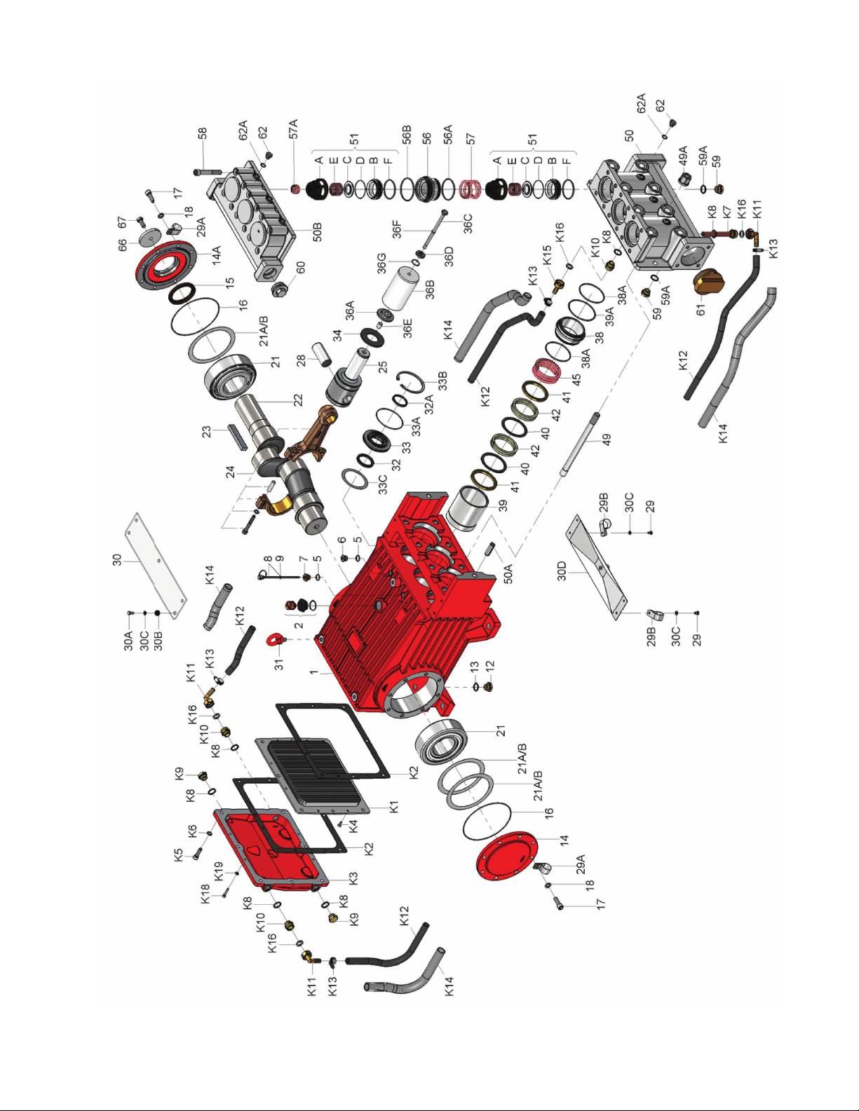
7.2 Suction and Discharge Valves
Loosenscrews(58),liftdischargevalvecasing(50B)
upandaway.
Takeoutpressuresprings(57).
Pulloutthecompletevalves(51)togetherwiththe
pressurevalveholder(56)usinganassemblytool
(orderno.07662).
To dismantle valves:
Thespringtensioncap(51A)isscrewedtogether
withthevalveseat(51B).
Screwoffspringtensioncap,takeoutsprings(51E)
andvalveplate(51C).
ChecksealingsurfacesandO-rings(51D,51F).
Replacewornparts.
Beforere-fittingthevalves,cleanthesealing
surfacesinthecasingandcheckforanydamage.
Tightenscrews(58)totherequiredtorque.
Checktorquetensionafter8-10operatinghours.
8.3 Seals and Plunger
Screwoffhexagonnuts(49A)andhosecoupling
(K11andK15),removepumpheadtogetherwithseal
case(38)fromcrankcase(1).
Ifnecessary,carefullytapthevalvecasing(50)past
thecentringstud(50A)usingarubberhammer.
Ifnecessary,supportthepumpheadby
restingitonwoodenblocksorbyusinga
pulley.
Removetensionscrew(36C)andtakesealsleeve
(39)togetherwithallmountedpartsoutofthedrive.
Pullplungerpipeoutofsealassemblyandcheckfor
anydamage.
Pulloutspiralrings(42),guiderings(41)andsupport
rings(40)andcheckforanydamage.
Becarefulnottodamagesealsleeve(39)
andguidering(41).
Checktheinnerdiameteroftheguidering
forwearandifnecessaryreplacetogether
withspiralring(42)andsupportring(40).
Cleanallparts.
Newpartsshouldbelightlycoatedwith
silicongreasebeforeinstallation.
Insertthesealunit(40,41,42,43)intothesleeve.
Pushtheceramicplungercarefullythroughtheseals
fromthecrankcaseside.Ifnecessary,thesealscan
beheldtightlyusingasuitablepipesupportheldon
theothersideofthesealsleeve.
Takeoutthesealcase(38)fromthevalvecasing
(50)andcheckO-rings(38A)(ifnecessarysecure2
screwdriversinthefrontO-ringgroovetoextractseal
casingfromvalvecasing).
Coatsealswithsilicongreasebeforeinstalling.
Mountingsurfacesofthecrankcaseand
valvecasingmustbecleanandfreeof
damage.
Thecomponentsmustlieexactlyand
evenlyononeanother.
Thesameexactnessappliesforall
centringpositionsinthecrankcase,
intermediatecasing,pressure-andvalve
casing.
Theymuststandverticallyoneachother.
Coatthesealsleevelightlywithanti-corrosivegrease
(e.g.molycoteno.Cu-7439)initsfittedareatowards
thecrankcase.
Insertsealsleevesintotheircrankcasefittings.
Coatthethreadsofthetensionscrew(36C)lightly
withthreadglueandinsertittogetherwithanew
copperring(36D)throughtheceramicpipe.
Turnthepumpbyhanduntiltheplunger(25)rests
againsttheplungerpipe.
Tightentensionscrewtotherequiredtorque.
Threadgluemustnevercomebetween
theplungerpipe(36B)andcentring
sleeve(36E).
Overtensioningoftheplungerpipeby
excessivetighteningofthetensionscrew
and/ordirtordamageonthemounting
surfacescanleadtoplungerpipe
breakage.
Insertthesealtensionspring(45)andO-rings(38A,
39A)intothesealsleeve(39).
Mounting Valve Casing:
Putsealcases(38)inthecentringholesofthevalve
casing,thenpushvalvecasingcarefullyontocentring
studs(50A).
Tightenhexagonnutsevenlyandcrosswisetothe
requiredtorque.
Thetorquetensiononthescrews(49A)
mustbecheckedafter8-10operating
hours;thepumpmustbeatzero
pressure.
Thereafterthetensionistobechecked
every200operatinghours.
If required, supplementary assembly instructions
can be requested from the manufacturer Giant
Industries.
GP8076 PUMP REPAIR INSTRUCTIONS