Gibus MEDITERRANEA Series User manual

ENG
LINE MEDITERRANEA
MODEL
MED JOY
ISLAND VERSION, LEANING VERSION, WALL
SINGLE MODULE, COUPLED
USE AND MAINTENANCE MANUAL
DECLARATION OF QUALITY
DECLARATION OF WARRANTY
DECLARATION OF PERFORMANCE DoP
MUT 104
Rev. 1
24/02/2020


Page 3of 52USE AND MAINTENANCE MANUAL
Code MUT 104
Rev. 1
WARNING: carefully read all warnings and instructions in this manual and in the
use and maintenance manual before carrying out any operation with the Bioclimatic
Pergola. Read in particular the chapter on safety.
Dear Customer,
thank you for choosing a Pergola by "Gibus", we are pleased to deliver this manual in order to
help you to use the product in the best possible way.
Please read carefully the recommendations described in the following pages and keep the manual
at hand for the Gibus specialist who will be responsible for management and maintenance of
the Pergola.
Gibus S.p.A.
via Luigi Einaudi, 35
35030 Saccolongo (PD) - ITALY
IMPORTANT NOTE:
For the sake of simplicity, in this manual the product may be referred to as “pergola”,
“awning” or “structure”.
The correct definition that identifies the product is “Bioclimatic Pergola”, with a
detailed description found in section 1.1 “Preliminary Information” and in Chapter
15 “Annexes”
www.gibus.com

Page 4of 52 USE AND MAINTENANCE MANUAL
Code MUT 104
Rev. 1
These instructions were translated from Italian (original language).
Gibus S.p.A. reserves all rights to this manual, including the right, at any time, to make any
necessary changes aimed at improving its products and the manual itself without prior notice.
The reproduction, even partial, of this manual is strictly forbidden without the permission of
Gibus S.p.A.
www.gibus.com

Page 5of 52USE AND MAINTENANCE MANUAL
Code MUT 104
Rev. 1
1 INTRODUCTION 7
1.1 Getting started 7
1.2 Warnings for use 7
1.3 Regulations and self-certification documentation 8
1.4 Liability 9
1.5 Identification of the product and technical nameplate 9
2 SAFETY PRECAUTIONS 10
2.1 Purpose and intended use of the pergola 10
2.2 Use environment 11
2.3 Standard safety devices 11
2.4 Optional safety devices 11
2.5 Requirements of the user and installer 12
2.6 Recommendations 12
3 TECHNICAL DESCRIPTION 13
3.1 Structural and Mechanical Components 14
3.2 Electrical components 14
3.3 Electronic components of the awning (optional) 16
3.4 Noise level 16
4 TECHNICAL DATA 17
4.1 Type 17
4.2 MED JOY ISLAND 18
4.3 MED JOY FRONTAL LEANING VERSION 20
4.4 MED JOY LATERAL LEANING VERSION 22
4.5 MED JOY WALL 24
4.6 Coupling module 26
5 PACKING, HANDLING AND TRANSPORTATION 28
6 SAFE INSTALLATION 29
6.1 Mechanical structure 29
6.2 Electrical connections 30
6.3 Radio control 31
7 INSTRUCTIONS FOR PROPER INSTALLATION 32
8 OPERATION AND USE OF THE PERGOLA 33
9 MAINTENANCE 37
9.1 Cleaning the brise soleil blades 37
9.2 Maintenance of the Pergola 38
9.3 Extraordinary maintenance 38
10 DISASSEMBLY AND DISPOSAL 39
10.1 Disposing of the Pergola 39
TABLE OF CONTENTS
www.gibus.com

Page 6of 52 USE AND MAINTENANCE MANUAL
Code MUT 104
Rev. 1
TROUBLESHOOTING 40
11.1 Faults and failures table 40
12 5-YEAR WARRANTY (EU countries + Switzerland) 42
12.1 Object of the warranty 42
12.2 Duration 42
12.3 Remedies provided as per Art. 133 of consumption code Leg. Decree 206/2005 42
12.4 “Without charges” 42
12.5 Territorial extension 42
12.6 Standards for warranty validity 43
12.7 Exclusions 43
12.8 Liability of the manufacturer 43
12.9 Final indications 43
13 MED JOY EXPLODED DRAWING 44
13.1 MED JOY 1 MODULE - ISLAND/LEANED 44
13.2 MED JOY COUPLED ON THE FRONT - ISLAND/LEANED 45
13.3 MED JOY COUPLED ON THE SIDE - ISLAND/LEANED 46
13.4 MED JOY 4 MODULES (CROSSED VERSION) - ISLAND/LEANED 47
14 DOCUMENTATION 48
14.1 Declaration for correct installation 48
14.2 Maintenance registry 50
14.3 Production notes 50
15 ANNEXES 51
TABLE OF CONTENTS
www.gibus.com

Page 7of 52USE AND MAINTENANCE MANUAL
Code MUT 104
Rev. 1
CHAPTER 1: INTRODUCTION
Do not destroy and change, if needed just supplement with inserts published by the manufacturer.
This manual refers to the product:
Type of awning: Bioclimatic Pergola, isolated or leaning against the wall, for outdoor use.
Line: MEDITERRANEA
Models: MED JOY (ISLAND - LEANING VERSION)
Revision No. 01
Published: 20/02/2019
Manufacturer's data: Gibus S.p.A. via L. Einaudi, 35 - 35030 SACCOLONGO (PD) - ITALY
List of annexes: Installation instructions - Motors and automatisms instructions - Delivery
certificate.
Each operator and personnel in charge of the installation, adjustments, operation and
maintenance of the Bioclimatic Pergola, must read very carefully this manual and observe the
instructions given, the operator in charge of the installation and maintenance must also meet the
qualification requirements for the use and maintenance of the Pergola.
PRELIMINARY INFORMATION
1.1
IMPORTANT: The instruction manual is aimed at those who use the Bioclimatic
Pergola, such as an installer, maintainer, owner or user and is the basis for the correct
use and maintenance of the product. Addressed to the installer are the instructions
for handling, unpacking, installation, adjustment and maintenance. Addressed to the
owner are the instructions for proper use, maintenance and disposal, as well as the
warranty. This manual is an integral part of the product. Keep it intact and in an
easily accessible place for future reference and at hand for further consultation until
the disposal of the Bioclimatic Pergola. In case of loss or destruction of the manual,
the customer must request a new copy to his Retailer, providing the main data of the
product and the destination of the new copy. When selling this manual must follow
the Bioclimatic Pergola to its new destination. The manual must always be available
to the qualified installation, maintenance or control personnel for the necessary
registration. The Manufacturer reserves the right to update products and relevant
manuals, with no obligation to update previous manuals.
This manual is the essential tool for maintaining the validity of the guarantee.
INSTRUCTIONS FOR USE
1.2
The instructions contained in this manual are intended for models:
- MED JOY ISLAND: Bioclimatic self-supporting stand-alone pergola with cover formed of a brise
soleil with swinging metal blades, available in single or multi-module, with coupling modules.
- MED JOY LEANING VERSION: Bioclimatic wall-leaning pergola with cover formed of a brise
soleil with swinging metal blades, available in single or multi-module, with coupling modules.
- MED JOY WALL: bioclimatic pergola applied to walls with cover formed of a brise soleil with
swinging metal blades, available in single or multi-module, with coupling modules.
www.gibus.com

Page 8of 52 USE AND MAINTENANCE MANUAL
Code MUT 104
Rev. 1
WARNING: DANGER TO THE OPERATOR/USER In reference to dangerous
situations that can occur with the use (including installation and maintenance) of
the Pergola. Failure to comply with these messages may endanger the safety of
persons and the product.
WARNING: In reference to dangerous situations that may occur due to the
PRESENCE OF ELECTRICAL VOLTAGE. Failure to comply with these messages
may endanger the safety of persons and the integrity of the product.
WARNING: In reference to dangerous situations that can occur with the use of the
Pergola to prevent damage to objects and the Pergola itself.
IMPORTANT: Useful information and tips to be observed to ensure proper use
and preservation of the Pergola. Failure to observe these messages can affect the
integrity and / or resistance of the product.
This User's Manual was prepared in accordance as indicated in EN 13561 and and with section
1.7.4 of Annex 1 to Directive 2006/42/EC taking into account the normal use of the Pergola in
order to inform, together with other instructions for use affixed to the pergola itself or in the
installation instructions, the operators / users on residual risks that the products presents.
The Bioclimatic Pergola complies with the “Construction products regulations - CPR 305/2011”
and the requirements given in the Annex ZA of the EN 13561, “assessment and inspection
system for performance continuity type 4” (System 4).
If it is installed properly, it has a resistance to wind as shown in the technical data table in section
4, according to the size, in each case greater or equal than those required by the Class 4 of the
UNI EN 13561 rule on “External awnings - Performance requirements including safety”.
This Technical Classification ensures resistance to a wind that carries a maximum pressure rating
of 170 [N/m2] (Newton/sqm) similar to an wind insisting on the awning with a maximum speed of
60 [km / h] corresponding to the 7th level of the Beaufort Scale. The resistance to wind load was
evaluated according to criteria related to those required by the UNI EN 13561 and UNI EN 1932
rules and from the technical standards in force, with the necessary safety margins.
The Pergola complies as well as the relevant parts of the Machinery Directive 2006/42/EC.
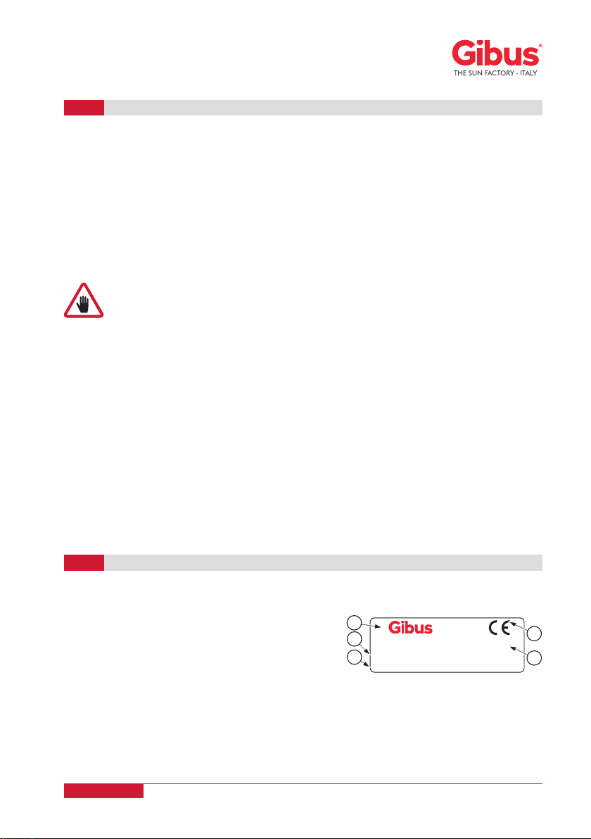
The CE Mark together with wind resistance characteristics according to UNI EN 13561 and the
self-certification document (Declaration of Performance DoP) are included in APPENDIX 0 and
APPENDIX 1 on the last pages of this manual. The original Declaration of Performance DoP
issued by the manufacturer is kept by Gibus S.p.A.
REGULATIONS AND SELF-CERTIFICATION DOCUMENTATION
1.3
The instruction manual must be read and used in the following way:
- Read this manual carefully, and consider it an integral part of the Pergola;
- The instruction manual must be readily available for use by staff in charge of running and
maintenance;
- Keep the manual for the entire service life of the Pergola;
- In case of sale deliver the manual to the new owner of the Pergola;
- Use the manual in such a way not to damage its content;
- In no case remove, tear or re-write any part of the manual;
- Keep the manual in a place protected from moisture and heat;
- If the manual is lost or partially damaged and then its complete content can no long be read, it
is advisable to request a new manual to the manufacturer.
In the following pages pay close attention to the following symbols and their meaning. Their
function is to highlight essential information such as:
www.gibus.com

Via Einaudi, 35 - 35030 Saccolongo (PD) 2006/42/CE
EN 13561
MODELLO: MED JOY - 230V/50Hz
MESE: 1 2 3 4 5 6 7 8 9 10 11 12 ANNO: 2019 - 20 - 21
D
EC
B
A
Page 9of 52USE AND MAINTENANCE MANUAL
Code MUT 104
Rev. 1
WARNING: For maintenance or repair to always use only original spare parts.
Gibus SpA declines all responsibility for damages that may occur for non-
compliance with the above instructions. The Pergola is guaranteed according to
the contractual arrangement prepared at the time of sale. The warranty is in any
case deemed void if the rules and instructions for use and maintenance contained
in this manual were not followed.
RESPONSIBILITY
1.4
Gibus SpA is not liable and has no obligations for any accidents to persons or property, which
may occur due to:
- Failure to follow the instructions in this manual regarding the installation, use and maintenance
of the Pergola;
- Violent actions or mishandling in the installation, use and maintenance of the Pergola;
- Changes made to the Pergola without the prior written permission by Gibus SpA;
- Incidents in any case arising beyond the normal and correct use of the Pergola.
In any case, if the user thinks the cause of the incident is a defect of the Pergola, he will have to
prove that the damage has been a consequence of such a "defect".
Each model is identified by the adhesive technical nameplate showing the CE marking sign and
contains the following data:
A Name and address of the registered office of the manufacturer.
BCE marking
C No of the European rule.
D Model of the awning and specifications.
EYear of manufacture.
IDENTIFICATION OF THE PRODUCT AND TECHNICAL NAMEPLATE
1.5
Each Gibus awning and pergola is unique, individually recognisable and traceable due to the
Gibus trademark 3D hologram with a unique alphanumeric serial number. All Gibus products
are supplied with the hologram (see back cover). The hologram is applied near the CE marking.
Quick or careless preparation leads to improvisation, which is the cause of many accidents.
Before starting the installation work and before commissioning of the Pergola, carefully read and
observe the following tips:
- Program all operation with the utmost care;
- Be well aware of where and how it is provided for the use and maintenance of the Pergola;
- Strictly follow all warnings relating to special dangers listed in this manual;
- The maintainer must always have at hand the instruction manual;
- A constant and careful preventive maintenance will always ensure a high level of operating
safety of the Pergola. Never postpone needed repairs and have them carried out only by
qualified personnel, and use only original spare parts.
www.gibus.com

Page 10 of 52 USE AND MAINTENANCE MANUAL
Code MUT 104
Rev. 1
The Bioclimatic Pergola was designed and made for protection from the sun and rain and it is
meant to be used in civil constructions, residential and commercial buildings and other facilities
for the community.
The Bioclimatic Pergola is not able to withstand snow load. Therefore should it snow, the
blades must be placed vertically (open) before the snow settles on them.
It is advisable to use the snow sensor, temperature sensor combined with the rain sensor, to
detect snow and prevent it depositing.
In all cases, do not stand under or near the pergola if any snow has deposited on it (*).Any
other use is considered improper and inadequate and releases the manufacturer from all
liability for any damage caused to persons or property.
The Bioclimatic Pergola offers, if properly installed, a resistance to wind load greater or equal
than those required by the Class 4 of UNI EN 13561. It is therefore recommended the exposure
to a wind exerting a maximum pressure of 170 Newton/sqm, corresponding to the load of a
continuous wind speed not exceeding 60 km/h.
It is strictly required, for the sake of safety, to open the swinging metal blades vertically
before the given limit is reached (even though the pergola offers much higher wind
resistance depending on its size).
CHAPTER 2: SAFETY REQUIREMENTS
PURPOSE AND INTENDED USES OF THE PERGOLA
2.1
IMPORTANT: For any doubt or unintended use, consult the authorized dealer or
the manufacturer before installation.
The manufacturer is not liable for malfunctions and damage if the Pergola:
- Is used for purposes other than those for which it is intended to;
- Is not operated and maintained in accordance with the instructions specified in this manual;
- Is not subject to regular maintenance, as prescribed, or non-original spare parts are used for
replacement.
(*) The MED JOY structure is designed to withstand a static load from deposited snow of at least
60 kg/m2(without wind).
(**) In the event of ice, it might be difficult to open the blades if they are in a horizontal position
(i.e. closed).
CAUTION: for safety reasons the brise soleil blades on the pergola must be
placed vertically in case of wind exceeding the recommended maximum exposure,
very strong rain, hail, snow and ice; it is very dangerous to leave blades placed
horizontally in these cases, it can cause injury to persons and damage to property.
Do not stand under or near the pergola if any snow has deposited on it.
IMPORTANT: In order to use the Pergola for purposes other than those described
above, a specific permission given by the manufacturer is required. Failure to
follow the conditions for proper use, voids any warranty given by the manufacturer.
www.gibus.com

Page 11 of 52USE AND MAINTENANCE MANUAL
Code MUT 104
Rev. 1
USE ENVIRONMENT
2.2
The Pergola was designed and built to be used outside. It offers adequate protection of the
electrical parts to water infiltration. The motors and the control units provides a degree of
protection against moisture equal to at least IP44.
The Pergola can also be used outdoors or away from the wall of a building (intended use),
provided that the system is degree of protection IP55.
It needs a 230V/50Hz power supply. Install an upstream electrical switch suitable to 230V/50Hz
with magnetothermal and differential functions (see paragraph 6.2. “ELECTRIC CONNECTION”).
The electrical switch should be placed in a protected position, in an easy to reach position, high
from the ground and away from dangerous areas.
CAUTION: the engines cannot be used in atmospheres posing risk of explosion.
CAUTION: No person should install or place ladders or other fixed objects in such
a way as to obstruct the movement of the blades.
ATTENTION!: Corrosion resistance is not guaranteed in the event of immersion or
sprays with salt water (sea storms, etc.). Also, with intense exposure to salty fog,
incrustations or bubbles could appear in the connections or aluminium profiles
and oxide or rust could appear on the stainless steel brackets. These conditions
are not covered by warranty.
IMPORTANT: The temperature sensor can be activated by the remote control/set
up transmitter. See the specific instructions of the control unit supplied with the
accessory box.
STANDARD SAFETY DEVICES
2.3
Temperature sensor:
The sensor detects the temperature that could cause the freezing of the pergola slats. If it is
under 2°C the alarm is activated, then the control unit moves the slats at the 66% of the opening.
The alarm is off when the temperature is over 3°C.
The control unit performs just hold-to-run commands during the status of alarm, and resumes
its normal operation when the alarm is not active anymore. By default the sensor is deactivated.
Alarm priority: MEDIUM.
OPTIONAL SAFETY DEVICES
2.4
Wireless wind sensor:
High priority sensor. Enabled by default. The anemometer detects the wind speed.
The alarm is present when the detected speed is over the set threshold. When the alarm is
present, the control unit moves the pergola profiles up to 33% of their complete opening. The
control unit does not execute any commands. The alarm does not activate when the sensor
detects for 60 seconds that the speed is lower than the set threshold.
IMPORTANT: the wind sensor can’t be enabled/disabled from the remote control
or control unit but only from the sensor itself. See the specific instructions of the
sensor supplied with the accessory box.
www.gibus.com

Page 12 of 52 USE AND MAINTENANCE MANUAL
Code MUT 104
Rev. 1
The normal use of the Bioclimatic Pergola is allowed to everyone, except those younger
than 12 years. The installation of the Bioclimatic Pergola and of the electrical system, the
adjustment of the Pergola and the setting of the engines limit switch, as well as maintenance
must be performed by qualified personnel only. The installation of the Pergola adjustments
must be performed strictly in accordance with the manufacturer’s instructions provided in
this manual and especially following the attached Installation Instructions referred to in the
pertinent sections of this manual (Chap. 6 and Chap. 7).
USER AND INSTALLER REQUIREMENTS
2.5
Rain sensor:
When the sensor detects the rain and the alarm is activated, the device positions the slats of the
pergola in closed position. The device doesn’t perform any command during the status of alarm.
The alarm is off when the sensor doesn’t detect the presence of the rain for 20 seconds. By
default the sensor is activated. Alarm priority: LOW.
Functioning of the system AFTER the rain alarm (Water draining):
Once the rain alarm is off, for the next 6 hours, as soon as a command of automatic movement
sent by transmitter is received, the control unit will move the slats to 33%, to allow the water
draining. For 4 minutes the control unit will perform just hold-to-run commands, switching off
the alarm status.
Snow condition (temperature sensor combined with rain sensor):
To manage the alarm related to the condition of snow it’s necessary combine temperature sensor
and rain sensor. The alarm is on when the temperature is under 2°C and the rain has been
detected, then the control unit moves the slats at the 66% of the opening.
The alarm is off when the temperature is over 3°C or when there is no rain detection. The control
unit performs just hold-to-run commands during the status of alarm, and resumes its normal
operation when the alarm is not active anymore. By default the combination is deactivated.Alarm
priority: MEDIUM.
In the manual and especially in the attached Installation Instructions referred to in the pertinent
sections of this manual (Chap. 6 and Chap. 7), are listed all instructions for proper handling,
storage, installation, use and maintenance of the Pergola, in compliance with the product
standards and the “Machinery Directive” and to avoid harm to people or damage to the Pergola
itself. Are also given instructions to perform properly both dismantling and disposal.
RECOMMENDATIONS
2.6
IMPORTANT: the rain sensor can be enabled/disabled from the remote control/set
up transmitter. See the specific instructions of the control unit supplied with the
accessory box.
IMPORTANT!: for further information about the control unit of motors and sensors
as well as for specific information, see the instructions supplied with the control
unit and sensors.
WARNING: The installation of the Pergola and its electrical connection,
are only to be carried out by specialized and authorized staff.
Any operation on the electrical system must be carried out by
trained personnel only. For any doubt or unintended use, consult the
manufacturer before installation.
www.gibus.com

Page 13 of 52USE AND MAINTENANCE MANUAL
Code MUT 104
Rev. 1
WARNING: The installation of the Pergola must be carried out in accordance
with the instructions in this manual. A different installation could result in
hazardous situations. In this regard see the sections “SAFE INSTALLATION” and
“INSTRUCTIONS FOR PROPER INSTALLATION” and the installation instructions
attached to this manual and inside the package.
WARNING: You can not alter or modify the Pergola. Any changes or modifications
made without proper authorization by the manufacturer, relieves the latter from
any liability for any damage that may result and void the warranty.
ATTENTION: it is strictly forbidden to carry out operations using open flames in
the vicinity of the Pergola.
Recommendations to be taken in the presence of staff (only if staff is working under the structure):
- if the structure is installed as a stand-alone structure, assess the lighting hazard according to
Law Decree 81/08 (in the Chapter III of Title III) by applying the technical reference regulations
such as CEI EN 62305-2 (CEI 81-10/2).
- If the structure leans against an existing building, carry out the lighting hazard assessment
again in accordance with Law Decree 81/08 (in chapter III of Title III) by applying the technical
reference regulations such as CEI EN 62305-2 (CEI 81-10/2).
CHAPTER 3: TECHNICAL DESCRIPTION
The Bioclimatic Pergolas of the MED JOY line were designed and built according to the principles
of constant innovation, impeccable workmanship and attention to detail by Gibus Total Quality.
A system of values designed to ensure complete customer satisfaction.
Gibus design interacts with nature to obtain maximum comfort and minimum energy waste.
The bioclimatic cover solutions can regulate the microclimate of the environment underneath
by creating natural ventilation. The aluminum blades that make up the cover are moved by
a motorized system and can rotate from the horizontal closed position, which guarantees an
excellent seal in case of rain, to the open position, according to an angle that varies from 0 to 120
degrees. The exposure to sun of the external side of the blades generates heat, which induces
a natural convective movement of air from down to up through the blades. pleasant, refreshing
breeze provides a comfortable environment without any mechanical intervention. Naturally and
without energy consumption.
Adjusting the blades permits modulating the cooling effect and the sunlight that filters into the
environment below, giving full control of the microclimate and one’s own comfort. Even if it rains
there is maximum protection because the blades have been designed to waterproof and permit
the flow of water only through the appropriate gutters integrated into the structure columns
(patented Side Seal). Naturally beautiful, efficient and reliable system that Gibus has developed,
filing patents for the innovative technological content.
www.gibus.com

Page 14 of 52 USE AND MAINTENANCE MANUAL
Code MUT 104
Rev. 1
The Bioclimatic Pergola is formed of a self-supporting structure or attached to a wall, made from
painted aluminium and with side self-supporting gutters, supporting legs measuring 130x130
mm and a cover formed of swinging brise soleil blades.
The couplings include stainless steel brackets, painted aluminium parts, stainless steel nuts
and bolts. The linear actuators are activated by a radio-controlled system and they transmit the
movement to the blades. The profiles, adjustable blades and the bearing structure are made
of aluminium alloy EN AW 6060 UNI EN 573-03 UNI EN 755-2, treated with an anticorrosion
treatment and thermosetting polyester powder paint. The plastic components are melted in
fiberglass and nylon plastic. Stainless steel screws.
STRUCTURAL AND MECHANICAL COMPONENTS
3.1
MED JOY ISLAND is a bioclimatic pergola made of moveable brise soleil aluminium blades and
integrated in a special and dedicated self-supporting structure. It is installed in a stand-alone way
and isolated from any building.
For the MED JOY LEANING VERSION, the structure is dedicated and must be leaned against
the wall of a building.
MED JOY WALL is installed attached to the wall of a building.
The cover is formed of openable and moveable metal blades. When it is sunny, open the blades
to provide the required shade for improved outdoor comfort and a natural airflow that carries
the hot air upwards. When it rains the closed blades offer protection and carry the water to
the gutters incorporated in the supporting structure. The linear motor moves the blades by the
remote control. The Pergola is equipped with several patented systems to facilitate and speed
up the installation work and improve the performance of the product:
Gibus Patent®Quick Assembly: Quick connection system of the supporting structure
free from exposed fastening elements.
Gibus Patent®Side Seal: a side holding system for the blades resting on a seal along
the inside edge that provides isolation from the outside.
ATTENTION!: Corrosion resistance is not guaranteed in the event of immersion or
sprays with salt water (sea storms, etc.). Also, with intense exposure to salty fog,
incrustations or bubbles could appear in the connections or aluminium profiles
and oxide or rust could appear on the stainless steel brackets. These conditions
are not covered by warranty.
24VDC linear actuator motors move the blades of the Bioclimatic pergola and are controlled
by a control unit that fits a 230VAC/24VDC feeder. The motors provide a maximum push or pull
strength of 2000 [N], Protection class: IP66, Stroke length: 200 mm, noisiness level: max. 55 db
(A), Operating temperature:
-15 °C ÷+55 °C. The control unit supplies and controls the motors and the LED lights. Control
unit, 200- 240V~ +/-10% input, 24V DC +/-5% output, 140W - 240W max power, 868.3 MHz
radio frequency, IP 55.
ELECTRICAL COMPONENTS
3.2
Gibus Patent®Blade Seal: Blades sealing system.
www.gibus.com

Page 15 of 52USE AND MAINTENANCE MANUAL
Code MUT 104
Rev. 1
CAUTION: the power supply group has an electrical insulation of Class II. Don’t
ground the structure with the following attentions:
WARNING: the vertical side awnings have tubular motors with electrical insulation
levels lower than class II. The bioclimatic pergola must be grounded according to
the diagram shown in the Installation Instructions.
WARNING: even if there are accessories and parts powered at 230V/50Hz with
an electrical insulation level lower than class II (for example, the heaters or snow
melters), the bioclimatic pergola must be grounded according to the diagram
shown in the Installation Instructions.
Upstream a magnetothermal and differential switch must be installed with the characteristics
defined in the table below. If there is more than one output line from the pergola, each single
line must be protected. Provide power cables as defined in the table below.
(*): Or different depending on the place of installation.
MED JOY Electric Features
Type Bioclimatic pergola.
Power supply 230 V (+10% +15%) 50Hz (*)
Max. absorbed power
250 W (max. 1,5 A) for standard configuration modules (blade movement
and Spot White lights).
+max. 320 W with RYB leds
+max. 600 W with antifreeze system
Tot. max. 1200 W (5.2 A)
Refer to the labels on the outputs on each single line.
For the other accessories, refer to the power levels defined in the catalogue.
Insulation class
Class II (the structure must not be earthed) for standard configuration
modules (blade movement and Spot White lights and with RYB).
Class I (the structure must be earthed) with side awnings or heaters).
Connection mode by IP68 Male/female connector.
Power cable
(supplied by the customer)
YOU NEED a double insulated cable. Provide a cable: H07RN-F type with
minimum formation dependent on power
For max power: up to 2 kW up to 3 kW up to 5 kW
Up to 30 m 3G 1,5 mm23G 2,5 mm23G 4,0 mm2
Up to 50 m 3G 2,5 mm23G 4,0 mm23G 10,0 mm2
Upstream protection
(supplied by the customer)
Magnetothermal switch and differential switch with intervention current 0,03 A.
Type of differential protection: A (**).
For max power: up to 2 kW up to 3 kW up to 5 kW
Magnetothermal switch
features: 2 10A poles Curve C 2 16A poles Curve C 2 25A poles Curve C
Protection against
overvoltage None (provide the electric board with a suitable SPD protection system).
Operating temperature -20°C / +55°C
Degree of protection IP 54
(**): If there is more than one output line from the pergola, each single line must be protected.
In the case of antifreeze system, the differential must have an intervention current of 0.01A (dedicated line).
In case of Schuko socket, the differential must be of the AC type and the intervention current of 0.03A.
www.gibus.com

Page 16 of 52 USE AND MAINTENANCE MANUAL
Code MUT 104
Rev. 1
ELECTRONIC COMPONENTS OF THE AWNING (OPTIONAL)
3.3
Upon optional request the Bioclimatic Pergola can be managed electronically in its functions
with control of the weather conditions. In this case, the Bioclimatic Pergola can be fitted with
additional electronic sensors for wind, rain, temperature, and snow (see paragraph 2.3 and 2.4).
The type of electronic component used on the Pergola is indicated in the product chart.
CAUTION: Never set the wind speed above the wind resistance of the awning itself
(maximum threshold recommended for MED JOY brise soleil blades: 60 km/h).
IMPORTANT: The installation and maintenance instructions of the control units and
sensors are attached to the control unit packages, which are delivered along with
the Bioclimatic Pergola or placed in the accessory box. These instructions must
be read, annexed to this manual and keep in good condition for any subsequent
consultation.
The measured noise (sound pressure level) was less than 55 dB (A).
NOISE LEVEL
3.4
IMPORTANT: The instructions specific for engines and controls are supplied upon
delivery of the Bioclimatic Pergola. These instructions must be read, annexed to
this manual and keep in good condition for any subsequent consultation.
www.gibus.com

Page 17 of 52USE AND MAINTENANCE MANUAL
Code MUT 104
Rev. 1
TYPE
4.1
MED JOY ISLAND (Basic Module)
With 4 legs:
Width up to 450 cm
Projection up to 610 cm
With 2 legs:
Width up to 450 cm
Projection up to 610 cm
With 2 legs:
Projection up to 450 cm
Width up to 610 cm
With 4 wall attachments:
Width up to 450 cm
Projection up to 610 cm
With 6 legs:
Width up to 450 cm
Projection up to 690 cm
With 4 legs:
Width up to 450 cm
Projection up to 690 cm
With 4 legs:
Projection up to 450 cm
Width up to 690 cm
With 6 wall attachments:
Width up to 450 cm
Projection up to 690 cm
MED JOY FRONTAL LEANING VERSION (Basic Module)
Tubular motor parallel to the wall
Tubular motor perpendicular to the wall
MED JOY LATERAL LEANING VERSION (Basic Module)
MED JOY WALL (Basic Module)
CHAPTER 4: TECHNICAL DATA
www.gibus.com

S
L
S
L
S
273
L
240 33
S
L
S
L
S
273
L
240 33
L
G
200 225 250 275 300 325 350 375 400 425 450 G L
kg n° n°
210 182 192 202 212 222 231 241 251 261 271 280
4
9
230 191 202 212 223 233 244 255 265 276 286 295 10
250 200 211 223 234 245 256 268 279 290 301 310 11
270 209 221 233 245 257 269 281 293 305 316 325 12
290 218 231 243 256 269 281 294 306 319 332 340 13
310 227 241 254 267 280 294 307 320 333 347 360 14
330 236 250 264 278 292 306 320 334 348 362 375 15
350 245 260 275 289 304 318 333 348 362 377 390 16
370 254 270 285 300 316 331 346 361 377 392 405 17
390 264 280 295 311 327 343 359 375 391 407 415 18
410 275 292 308 325 342 358 375 391 408 425 435 19
430 284 302 319 336 353 371 388 405 422 440 450 20
450 293 311 329 347 365 383 401 419 437 455 470 21
470 303 321 340 358 377 395 414 433 451 470 480 22
470 312 331 350 369 389 408 427 446 466 485 495 23
510 321 341 361 380 400 420 440 460 480 500 510 24
530 330 350 371 392 412 433 453 474 494 515 525 25
550 339 360 381 403 424 445 466 488 509 530 540 26
570 348 370 392 414 436 458 480 502 524 546 555 27
590 379 400 426 449 470 490 510 535 555 578 490 28
610 389 412 436 459 482 505 529 552 575 598 610 29
630 398 422 446 470 494 518 542 566 590 613 630
6
30
650 407 432 456 481 506 530 555 579 604 629 640 31
670 416 442 467 492 517 543 568 593 618 644 660 32
690 425 451 477 503 529 555 581 607 633 659 670 33
Page 18 of 52 USE AND MAINTENANCE MANUAL
Code MUT 104
Rev. 1
MED JOY ISLAND
4.2
Side view Front View
4 legs 6 legs
Legend:
kg = Total pergola weight including the supporting structure and brise soleil blades.
G = Legs.
L = Brise soleil blades.
PROJECTION “S” (cm)
WIDTH “L” (cm) 1 Module
ISLAND - SINGLE MODULE
4 LEGS max. L x S 4.50 x 6.10
6 LEGS max. L x S 4.50 x 6.90
www.gibus.com

G L 200 250 300 350 400 450
210
4
9170 145 125 110 90 71
250 11 152 134 116 99 81 66
290 13 142 125 108 90 73 61
330 15 132 115 99 82 66 56
370 17 122 106 90 74 58 51
410 19 112 98 83 68 53 48
450 21 102 90 77 64 51 46
490 23 92 82 71 60 49 44
530 25 82 74 65 56 47 42
570 27 72 66 59 52 45 39
610 29 68 62 56 50 43 37
610
6
29 82 74 65 56 47 42
650 31 70 62 54 49 44 35
690 33 65 59 54 46 43 34
G L 200 250 300 350 400 450
210
4
9140 120 105 88 72 54
250 11 125 111 97 82 68 53
290 13 117 104 91 78 66 52
330 15 109 97 86 75 63 51
370 17 100 90 81 71 61 50
410 19 92 84 75 66 58 48
450 21 84 76 69 62 55 47
490 23 75 69 64 58 52 45
530 25 67 62 58 53 49 44
570 27 59 55 52 49 45 42
610 29 55 52 49 47 44 40
610
6
29 67 62 58 56 55 55
650 31 53 53 54 54 49 45
690 33 49 49 49 45 43 40
“ L”
“S” “ L”
“S”
G L 200 250 300 350 400 450
250
4
11 750 650 530 430 320 220
330 15 590 490 400 300 210 170
410 19 470 390 310 22 150 125
490 23 350 295 240 185 130 105
570 27 230 200 170 140 120 95
610 29 200 178 155 133 110 90
650 631 275 234 195 155 115 105
690 33 190 169 148 128 107 85
G L 200 250 300 350 400 450
250
4
11 500 420 350 280 210 140
330 15 380 325 260 200 140 110
410 19 305 250 200 150 100 80
490 23 220 190 150 120 85 70
570 27 140 120 105 90 70 55
610 29 120 107 93 80 65 50
650 631 180 153 125 98 70 65
690 33 120 107 93 80 67 55
“ L”
“S”
“ L”
“S”
Page 19 of 52USE AND MAINTENANCE MANUAL
Code MUT 104
Rev. 1
IMPORTANT: For each size the load shown in the table is still greater or equal than the one provided
by Class 4 - UNI EN 13561 / UNI EN 1932 (nominal load continuously distributed on the extended
surface equal to approximately 17 [kg/m2] or 170 [N/m2 ]).
The values reported in the table on the right, show the snow load resistance when there is no wind. The
pergola structure and cover are designed and certified to resist a deposited snow load (with no wind)
that varies by size.
In case of snow, it is advised to the blades must be placed vertically (open) before the snow settles
on them. Do not stand under or near the pergola if any snow has deposited on it.
Wind Resistance [kg/m2]
Without Integrated ZIP Screens
Wind Resistance [kg/m2]
Integrated ZIP Screens closed or semi-closed on 2 or 4 sides
Indicative Maximum vertical load [kg/m2]Snow load without wind [kg/m2]
LEGEND - “BEAUFORT” WIND SCALE
GRADE 12 GRADE 11 GRADE 10 GRADE 9 GRADE 8 GRADE 7 GRADE 6
Hurricane Force Violent storm Storm Strong gale Gale High wind Strong breeze
www.gibus.com

L
G
MM
S
L
S
L
S
273
L
240 33
S
L
S
L
S
273
L
240 33
200 225 250 275 300 325 350 375 400 425 450 G L
kg n° n°
210 160 170 180 190 200 209 219 229 239 249 260
2
9
230 169 180 190 201 211 222 233 243 254 264 275 10
250 178 189 201 212 223 234 246 257 268 279 290 11
270 187 199 211 223 235 247 259 271 283 294 305 12
290 196 209 221 234 247 259 272 284 297 310 320 13
310 205 219 232 245 258 272 285 298 311 325 335 14
330 214 228 242 256 270 284 298 312 326 340 350 15
350 223 238 253 267 282 296 311 326 340 355 365 16
370 232 248 263 278 294 309 324 339 355 370 380 17
390 242 258 273 289 305 321 337 353 369 385 395 18
410 253 270 286 303 320 336 353 369 386 403 415 19
430 262 280 297 314 331 349 366 383 400 418 430 20
450 271 289 307 325 343 361 379 397 415 433 445 21
470 281 299 318 336 355 373 392 411 429 448 460 22
470 290 309 328 347 367 386 405 424 444 463 475 23
510 299 319 339 358 378 398 418 438 458 478 490 24
530 308 328 349 370 390 411 431 452 472 493 505 25
550 317 338 359 381 402 423 444 466 487 508 520 26
570 326 348 370 392 414 436 458 480 502 524 535 27
590 357 378 404 427 448 468 488 513 533 556 465 28
610 367 390 414 437 460 483 507 530 553 576 590 29
630 376 400 424 448 472 496 520 544 568 591 600
4
30
650 385 410 434 459 484 508 533 557 582 607 615 31
670 394 420 445 470 495 521 546 571 596 622 630 32
690 403 429 455 481 507 533 559 585 611 637 650 33
Page 20 of 52 USE AND MAINTENANCE MANUAL
Code MUT 104
Rev. 1
MED JOY FRONTAL LEANING VERSION
4.3
Side view Front View
2 legs 4 legs
Legend:
kg = Total pergola weight including the supporting structure and brise soleil blades.
G = Legs.
L = Brise soleil blades.
PROJECTION “S” (cm)
WIDTH “L” (cm) 1 Module
FRONTAL LEANING VERSION
SINGLE MODULE
2 LEGS max. L x S 4.50 x 6.10
4 LEGS max. L x S 4.50 x 6.90
www.gibus.com
Other manuals for MEDITERRANEA Series
1
This manual suits for next models
1
Table of contents
Popular Lawn And Garden Equipment manuals by other brands

USP
USP Duramax 6 Ft Riverton-V2 Extension owner's manual

Pinnacle Outdoor
Pinnacle Outdoor 1.5m Flat Roof Series Assembly instructions

Iberica del Calor
Iberica del Calor TX8 instructions

MASSEY FERGUSON
MASSEY FERGUSON 160V - brochure

Riverlea
Riverlea GREENS HANDIMAN Assembly instructions

Oypla GARDEN
Oypla GARDEN 4299 user manual