Gicam RQ User manual

Loading Cells Digital Amplifier
RQ
INSTALLATION MANUAL
Rev. 0.2

INDEX
DEVICE PROPERTIES
TECHNICAL PROPERTIES Pag. 2
TECHNICAL PROPERTIES (follow) Pag. 3
SYMBOLS Pag. 3
WARNINGS Pag. 3
DEVICE ID TAG Pag. 3
DEVICE CONNECTIONS
DEVICE POWER Pag. 4
LOADING CELL CONNECTION Pag. 4
LOGICAL INPUT CONNECTION Pag. 5
RELE’ OUTPUT CONNECTION Pag. 5
SERIAL RS485 LINK UP (OPTION) Pag. 5
SERIAL RS232 LINK UP Pag. 6
ANALOG OUTPUT LINK UP Pag. 6
PROFIBUS LINK UP (OPTION) Pag. 7
DEVICENET CONNECTION (OPTION) Pag. 7
CONNECTION LIST Pag. 8
RQ: Device InstallationPag. 1

TECHNICAL PROPERTIES
RQ: Device Installation Pag. 2
Power 24 Vdc +-10% polarity revert protected.
Protection device with replaceable fuse.
Max Power tolerance 2 W (3W with field bus)
Insulation Class II
Working temperature -10°C +50°C (max 85% moist without water)
Stocking temperature -20°C +60°C
Weight Display Red led 5 digit numeric 7-seg (h 7 mm)
Led 2 3-mm led (output logic state)
Keyboard 3 mech button (behind the red front cover)
Dimensions 110 mm x 120 mm x 23 mm (l x h x p) attachment included
110 mm x 120 mm x 35 mm (l x h x p) field bus present
Installing material DIN profile support or OMEGA bar
Supporting material Self extinguishing PC/ABS blend
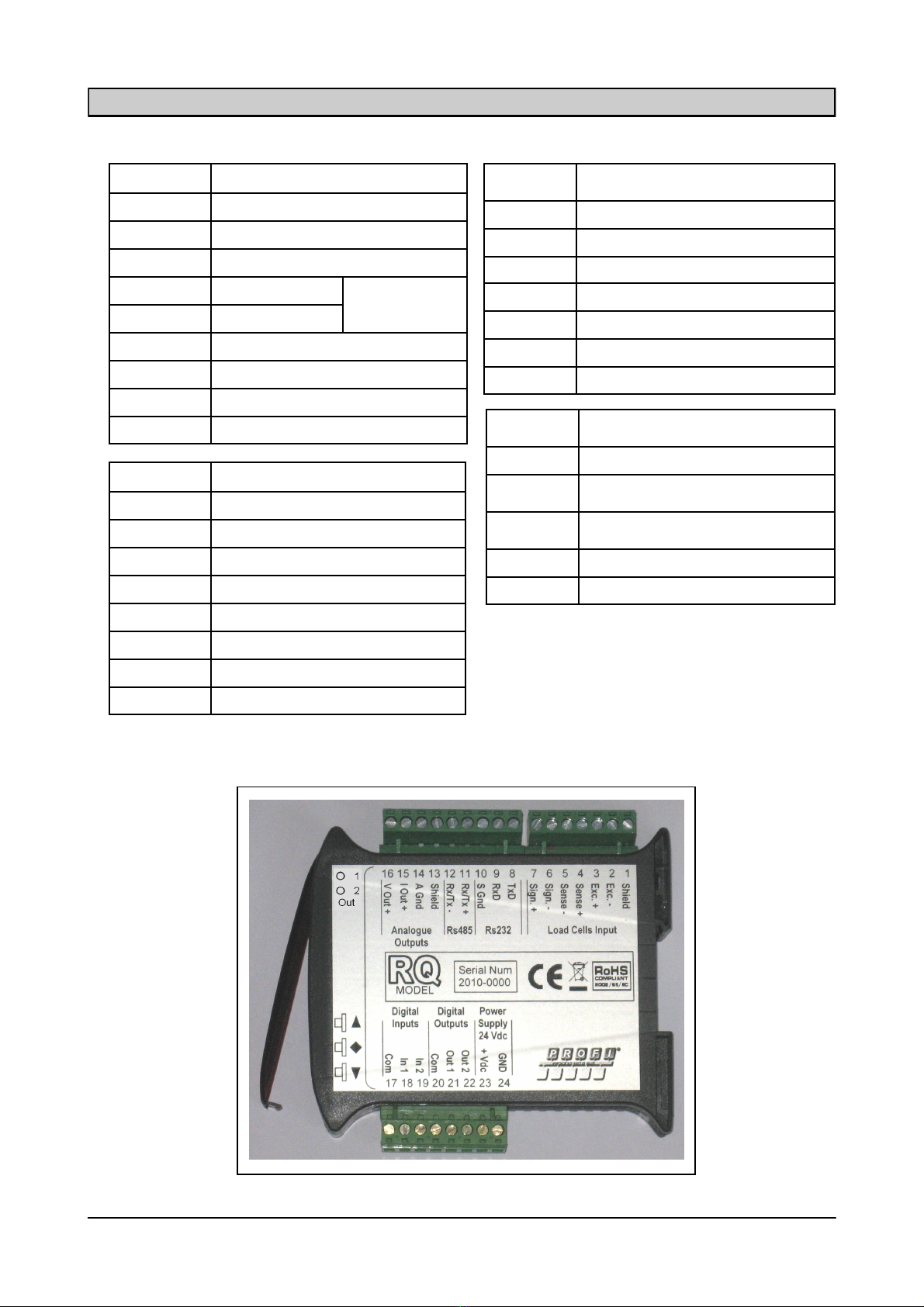
Connections Screw extract attachments size mm 5.08
The following are the setup data of
the cell input: max 4 (350 Ohm in line) o 8 700-Ohm cells.
Input voltage 4Vdc
Linearity < 0.01% lower edge
Shift in temperature < 0.001% lower edge / C°
Internal Resolve 16 - 24 bit
Field measure From -2.6 mV/V to +2.6 mV/V
Digital filter 0.1 Hz - 50 Hz on selection
Weight decimal char Between 0 and 3 char
Zero calibration and lower edge From keyboard.
Cable interrupt check Ever online
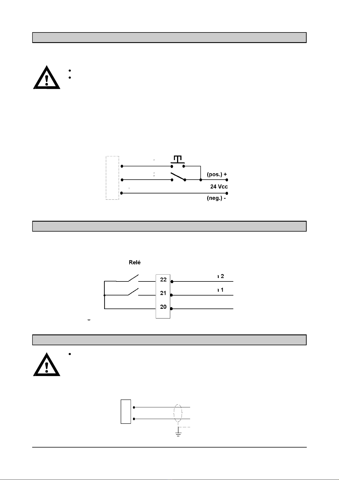
Logical output alarm 2 relè output (24 Vcc/Vac NA connection)
Rele’ maximum load 1A
Logical input N° 2 optoinsulated
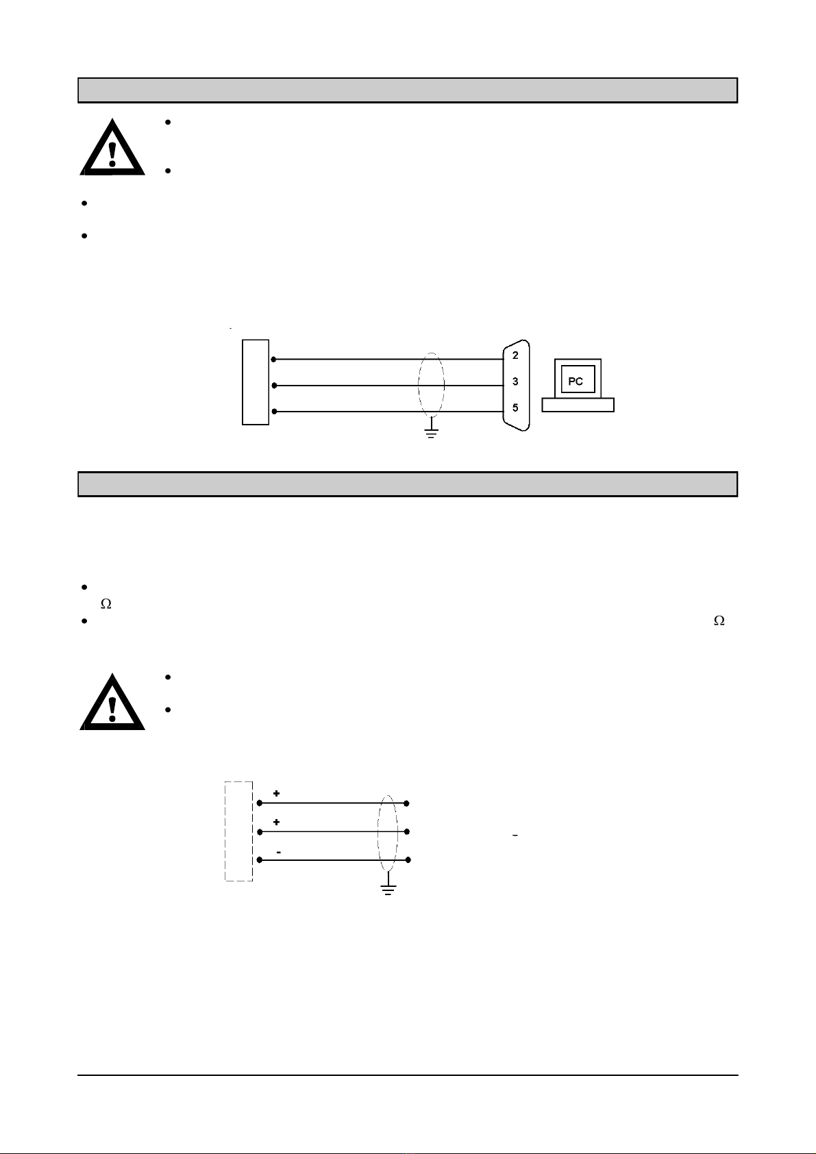
Serial Port Rs232 half duplex
Rs485 half duplex (opzionale)
Baud rate Fino a 115 kb/s (default 9600 b/s)
Maximum cable lenght 15m (Rs232) e 1000m (Rs485)
Field bus (OPTION) PROFIBUS DP-V1
DeviceNet
Next ...

In this section the signals used in this handbook to catch the reader’s notice:
Warning! This procedure has to be executed by authorized personnel.
Follow closely the following description.
More information.
SIGNALS
RQ: Device InstallationPag. 3
Analog output voltage ± 10 V / ± 5 V
Resolution 16 bits
Calibration From keyboard
Impede minimum 10K
Linearity 0.03% lower edge
Shift in temperature 0.002% lower edge / °C
Analog output Amperage 0 20 mA / 4 20 mA
Resolution 16 bits
Calibration From keyboard
Impede max 300
Linearity 0.03% lower edge
Shift in temperature 0.002% lower edge / °C
Memory for program code 32 Kbytes
Data memory 2 Kbytes
Law compliancy EMC EN61000-6-2, EN61000-6-3
Electrical Security EN61010-1
… Next TECHNICAL PROPERTIES
The following procedures must be executed by authorized personnel.
All the connection must be executed with the device offline and turned off
It’s important to report these data when requesting info or instructions regarding the device, more-
over it’s important to report the software version number and the release number (on the cover of
the operating handbook or shown at device startup).
WARNING
DEVICE ID TAG

The device is powered thru connectors 23 and 24.
The power cable must be kept aside from cables with different voltage, from the loading cells
cables and from those for the logic input/output.
The internal circuitry is fully insulated from the power voltage.
Voltage : 24 Vdc/ 10 % max 3W
CONNECTORS
23. + Alim.
24. 0
The cell’s (or cells) cable must not be kept in other cable’s conduit (i.e. output connected with
power cables or circuit breaker), but it must follow its own path.
If cable extensions are needed these are to be safely shielded, taking note of the color code
and the cable type stated from the device’s builder. The extension’s connection must be execu-
ted via soldering machines or via links or with a junction box that can be ordered aside.
The cable must have a number of connector not higher than the ones used (4 or 6). If more connectors
are present, link the remaining to –cell power (link 2).
No more than 4 350-ohm cells can be connected to the device. The voltage is 4 Vcc and is shielded from
temporary shortages.
The device field measure needs the use of loading cells with an accuracy between 1 mV/V and 2.5 mV/V.
The cable has to be connected to the terminals from 2 to 7 on the 7-pole extractable terminal. In the case
of a 4-connector cable, the terminal to be connected are the following (2-5 3-4).
Connect the cable shielding to terminal 1.
DEVICE POWER
LOADING CELLS CONNECTION
RQ: Device Installation Pag. 4
4 CONNECTOR
6 CONNECTOR
2. POWER -
3. POWER +
4. CONNECT TO TERMINAL 3
5. CONNECT TO TERMINAL 2
6. SIGNAL -
7. SIGNAL +
2. POWER -
3. POWER +
4. REFEER +
5. REFEER -
6. SIGNAL -
7. SIGNAL +
- SIGNAL
- SIGNAL
+ SIGNAL
+ SIGNAL
+ POWER
+ POWER
- POWER
- POWER
- REEFER
+ REEFER

LOGICAL INPUT CONNECTION
Both the logical input are shielded from the internal circuitry with an optoisolant.
The connection cable for the logical input is to be kept aside from power cables.
It has to be the shorter possible.
To activate a logical input it has to be linked to the positive end of a 24Vcc output while the
common connector is linked to the negative.
In the following diagram there 2 types of connection using a button on input 2 and a circuit breaker on input
1.
RELE’ OUTPUT CONNECTION
Both output are connected to a common via relè. Every connection has a voltage of 24 Vcc/Vac 1 A.
RQ: Device InstallationPag. 5
SERIAL RS485 LINKUP (OPTION)
This cable has to be kept aside from the others (power cables or cables connected to a
circuit breaker), and has to keep its own path.
11
12
TX/RX +
TX/RX -
18
19
17
1
2
D
E
V
I
C
E
input
input
common
D
E
V
I
C
E common
Output connect
Output connect

SERIAL RS232 LINKUP
To get a serial connection a shielded connection cable must be used, linking to mass the
shield at one of the ends. In the case that the cable should have more connectors than nee-
ded, the unused ones should have to be connected to the shielding material.
The serial connection cable must have a maximum lenght of 15 meters (as per EIA RS-
232-C rules), if the lenght is over that measure the device Rs422 interface must be used.
This cable must be set aside from others cable (power cables or the one connected to circuit breaker),
and it should follow a path on its own.
The personal computer used for the connection must be EN 60950 compliant.
The following is the diagram for the connection with a PC 9-poles connector:
8
9
10
ANALOG OUTPUT LINK UP
The device has two analog output one for the low frequency the other for the high.
Data:
Analog output high voltage: range between -10 and 10 Volt or between -5 and 5 Volt, minimum load 10K
Analog output low voltage: range between 0 and 20 mA or between 4 and 20 mA, maximum load 300 .
With a factory reset it is possible to have an output 0-10V or 0-5V.
To get the connection a shielded cable must be used, One of the end must be put to
ground.
Analog transmission can be disturbed by electo magnetic pulse. The cables must be shor-
ter as possible and directed on a path of their own.
RQ: Device Installation Pag. 6
15
16
14
PC Connector (9poles)
Data transmission
Data reception
Mass
Low Voltage
High Voltage
Shared
Analog Output

PROFIBUS LINK UP (option)
DSUB-9P male connector for the PROFIBUS cable
When this option is present the device is equipped in the lower side with a field bus PROFIBUS DP connec-
tor.
Data:
PROFIBUS baudrate from 9.6 kbps to 12 Mbps.
To get this connection a PROFIBUS cable must be used.
For the link up the file HMS_1810.GSD (given with the device) must be present on the
PLC/LC.
PROFIBUS LINE LINK UP
WARNING: if PROFIBUS connection is present, there can be no RS485 output.
DEVICENET LINK UP (opzionale)
RQ: Device InstallationPag. 7
The device, with this hardware setup, carries in the lower part a 5-pole extractable terminal.
Data:
DEVICENET baudrate 125, 250, 500 kbps.
DEVICENET LINE CONNECTION
PROFIBUS CABLE
5-poles male
connector

CONNECTION LIST
NUM. 9P terminale 5.08 mm
8RS232 TX
9RS232 RX
10 RS232 GND
11 RS485 +
OPTION
12 RS485 -
13 Display
14 Analog Output GND
15 Analog Output 4-20 / 0-20 mA
16 Analog Output ± 10V / ± 5V
NUM. 7P terminal 5.08 mm
6 cables cells version
1Display
2- cells power
3+ cells power
4+ refeer
5- refeer
6- signal
7+ signal
NUM. 8P terminal 5.08 mm
17 Common input
18 Input 1 (optoinsulated)
19 Input 2 (optoinsulated)
20 Common output
21 output 1 (24 Vdc relè 1A NA)
22 output 2 (24 Vdc relè 1A NA)
23 Power 24 Vdc
24 Powe 0 Vdc
NUM. 7P terminal 5.08 mm
4 cables cells version
1Display
2- Cell power
Bridge with terminal 5
3+ Cell power
Bridge with terminal 4
6- Signal
7+ Signal
RQ: Device Installation Pag. 8
Other manuals for RQ
4
Table of contents
Other Gicam Amplifier manuals
Popular Amplifier manuals by other brands

Northern Airborne Technology
Northern Airborne Technology SM251 Installation and operation manual

Audio Note
Audio Note SORO Phono Owner's Information

Goldenote
Goldenote S 1 owner's manual

ELECTROCOMPANIET
ELECTROCOMPANIET ECI 80D owner's manual

Omron
Omron K7L-AT50 Brochure & specs

Audio Authority
Audio Authority AMP-1235 Installation and operation