Gicam RQA User manual

Manuale
Manual
Handbuch

Manuale d’istallazione e d’uso
Installation and user manual
Installations- und Bedienungsanleitung
AMPLIFICATORE digitale/analogico per celle di carico
Digital / Analog load cell AMPLIFIER
Digital / Analog-VERSTÄRKER für Wägezellen

Sommario / Table of contents / Inhaltsverzeichnis
Sommario / Table of contents / Inhaltsverzeichnis ....................................................................1
Manuale d’installazione................................................................................................................3
Caratteristiche tecniche.................................................................................................................................. 3
Simbologia ..................................................................................................................................................... 4
Avvertenze ..................................................................................................................................................... 4
Targa identificativa dello strumento............................................................................................................... 4
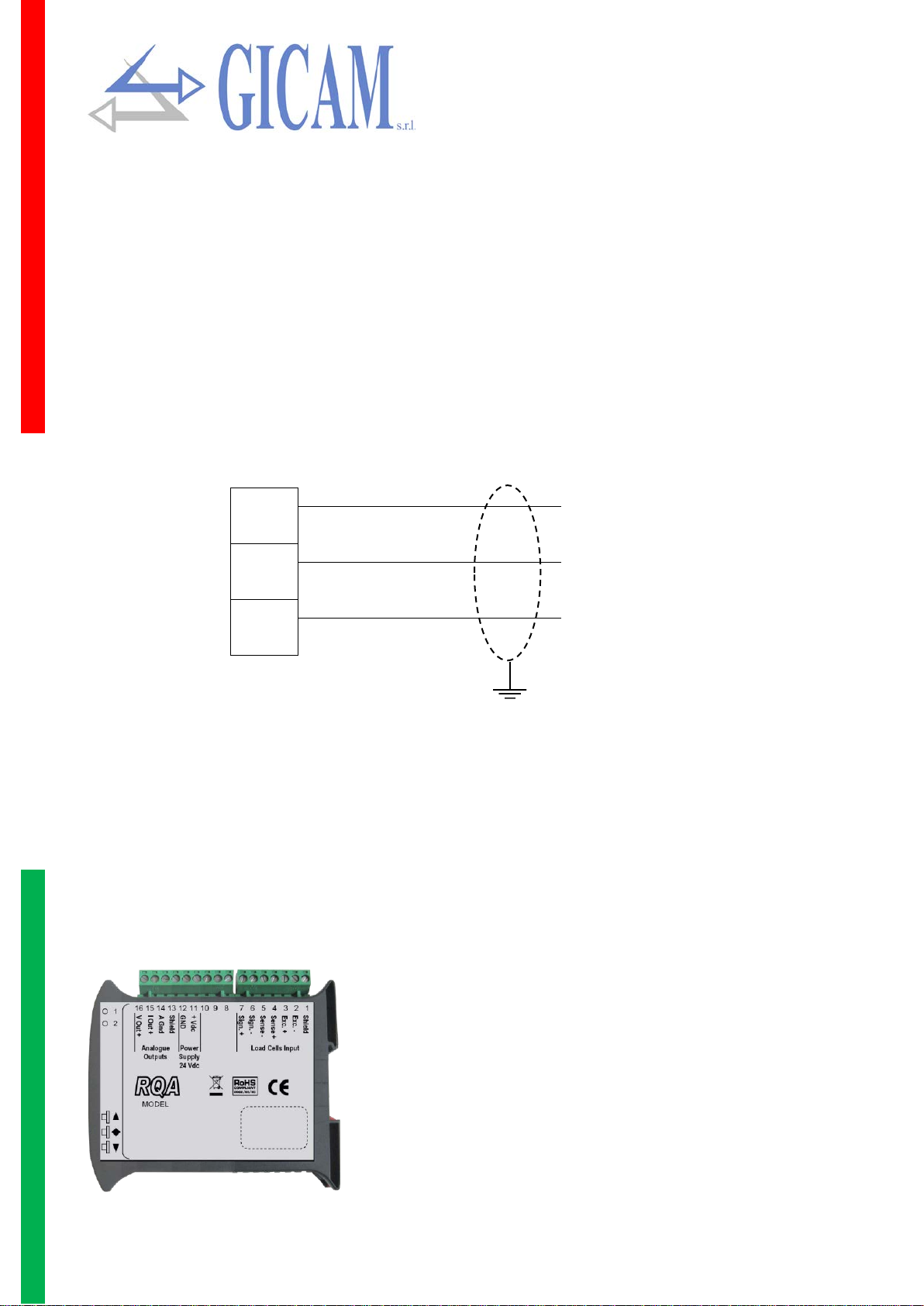
Alimentazione dello strumento....................................................................................................................... 5
Connessione delle celle di carico................................................................................................................... 5
Connessione uscite analogiche ..................................................................................................................... 6
Caratteristiche ............................................................................................................................................ 6
Connessione uscite analogiche ..................................................................................................................... 6
Manuale d’uso...............................................................................................................................7
Principali caratteristiche d’uso ....................................................................................................................... 7
Il panello frontale dello strumento.................................................................................................................. 7
Indicatori LED............................................................................................................................................. 7
Uso della tastiera ........................................................................................................................................... 7
Funzioni operative.......................................................................................................................................... 8
Impostazione filtro digitale.......................................................................................................................... 8
Correzione offset di zero dell’uscita analogica........................................................................................... 8
Correzione offset di span dell’uscita analogica.......................................................................................... 8
Installation manual .......................................................................................................................9
Technical specification................................................................................................................................... 9
Symbology ................................................................................................................................................... 10
Warnings...................................................................................................................................................... 10
Identification plate of the instrument ............................................................................................................ 10
Power supply of the instrument.................................................................................................................... 11
Connection of the load cells......................................................................................................................... 11
Connection of analog outputs...................................................................................................................... 12
Characteristics.......................................................................................................................................... 12
Analog output connection ............................................................................................................................ 12
User manual................................................................................................................................13
Main characteristics of use .......................................................................................................................... 13
Front panel of the instrument....................................................................................................................... 13
LED indicators.......................................................................................................................................... 13
Use of the keyboard..................................................................................................................................... 13
Operational functions................................................................................................................................... 14
Digital filter setting.................................................................................................................................... 14
Span offset correction of the analog output ............................................................................................. 14
Pagina – page – Seite 1

Installationsanleitung.................................................................................................................15
Technische Spezifikation ............................................................................................................................. 15
Symbole ....................................................................................................................................................... 16
Warnungen................................................................................................................................................... 16
Typenschild des Gerätes ............................................................................................................................. 16
Stromversorgung des Instruments............................................................................................................... 17
Anbindung der Wägezellen.......................................................................................................................... 17
Anschluss der analogen Ausgänge ............................................................................................................. 18
Eigenschaften........................................................................................................................................... 18
Anbindungen analoge Ausgänge................................................................................................................. 18
Bedienungsanleitung..................................................................................................................19
Hauptmerkmale der Benutzung ................................................................................................................... 19
Die Frontplatte des Instrumentes................................................................................................................. 19
LED Anzeigen........................................................................................................................................... 19
Benutzung der Tastatur................................................................................................................................ 19
Betriebsfunktionen ....................................................................................................................................... 20
Einstellung Digitalfilter.............................................................................................................................. 20
Nullpunktkorrektur des Analogausganges ............................................................................................... 20
Span-Korrektur des Analogausganges .................................................................................................... 20
Pagina – page – Seite 2

Manuale d’installazione
Caratteristiche tecniche
Alimentazione 24 V dc ± 10 % protetta contro l’inversione di polarità.
Protezione con fusibile ripristinabile
Assorbimento massimo 1 Watt
Isolamento Classe II
Categoria d’installazione Categoria II
Temperatura di stoccaggio - 20 °C / + 60 °C
Temperatura di funzionamento - 10 °C / + 50 °C
Umidità massimo 85% senza condensa
LED 2 LED da 3 mm (stato funzionamento)
Tastiera 3 pulsanti (dietro sportello rosso frontale)
Dimensioni d’ingombro 110 x 120 x 230 mm morsettiere comprese
Montaggio Supporto DIN o barra OMEGA
Materiale contenitore Mescola ABS/PC autoestinguente
Connessioni Morsettiere estraibili i vite, passo 5,08 mm
Ingresso celle di carico Massimo 4 celle di carico da 350 Ω in parallelo (o 8 celle da 700 Ω)
Alimentazione celle di carico 4 Volt corrente continua
Linearità 0,01 % del fondo scala
Risoluzione interna 16 – 24 bit
Deriva in temperatura < 0,001 % del fondo scala/°C
Campo di misura da -2,6 mV7V a +2,6 mV/V
Filtro digitale selezionabile 0,1 – 50 Hz
Numero decimali peso da 0 a 3 cifre decimali
Taratura zero e fondo scala eseguibile da pulsanti
Controllo interruzione cavi cella sempre presente
Uscita analogica in tensione ± 10 V / ± 5 V
Risoluzione 16 bit
Taratura digitale da pulsanti
Impedenza ≥ 10 kΩ
Linearità 0,03 % del fondo scala
Deriva in temperatura < 0,002 % del fondo scala/°C
Uscita analogica in corrente 0 – 20 A / 4 – 20 mA
Risoluzione 16 bit
Taratura digitale da pulsanti
Impedenza ≤ 300 Ω
Linearità 0,03 % del fondo scala
Deriva in temperatura < 0,002 % del fondo scala/°C
Conformità alle Normative EMC EN61000-6-2, EN61000-6-3
Conformità sicurezza elettrica EN61010-1
Pagina – page – Seite 3

Simbologia
Di seguito vengono riportate le simbologie utilizzate nel manuale per richiamare l’attenzione del lettore:
Attenzione! Questa operazione deve essere eseguita da personale specializzato.
Prestare particolare attenzione alle indicazioni seguenti.
Ulteriori informazioni
Avvertenze
Le procedure di seguito riportate, devono essere eseguite da personale specializzato.
Tutte le connessioni vanno eseguite a strumento spento!
Targa identificativa dello strumento
E' importante comunicare questi dati in caso di richiesta di informazioni o indicazioni riguardanti
lo strumento uniti al numero del programma e la versione che sono riportati sulla copertina del
manuale e vengono visualizzati all’accensione dello strumento.
!
i
i
Pagina – page – Seite 4

Alimentazione dello strumento
Lo strumento viene alimentato attraverso i morsetti 11 e 12.
Il cavo di alimentazione deve essere incanalato separatamente da altri cavi di alimentazioni
con tensioni diverse, dai cavi delle celle di carico e degli ingressi/uscite logici.
Il circuito interno è galvanicamente isolato dalla tensione di alimentazione.
Tensione di alimentazione: 24 Volt corrente continua, ± 10%, massimo 1 Watt
Connessione morsettiera: 11 – Alimentazione +
12 – Zero
Connessione delle celle di carico
Il cavo della cella (o delle celle) non deve essere incanalato con altri cavi (per esempio uscite
collegate a teleruttori o cavi di alimentazione), ma deve seguire un proprio percorso.
Eventuali connessioni di prolunga del cavo della devono essere schermate con cura, rispet-
tando il codice colori e utilizzando il cavo del tipo fornito dal costruttore. Le connessioni di
prolunga devono essere eseguite mediante saldatura, o attraverso morsettiere di appoggio
o tramite la cassetta di giunzione fornita a parte.
Il cavo della cella deve avere un numero di conduttori non superiore a quelli utilizzati (4 o 6).
Nel caso di cavo a più conduttori, allacciare i fili rimanenti al – alimentazione cella (morsetto
2)
Allo strumento possono essere collegate fino ad un massimo di 4 celle da 350 ohm in parallelo. La tensione
di alimentazione delle celle è di 4 V corrente continua ed è protetta da corto circuito temporaneo. Il campo di
misura dello strumento prevede l'utilizzo di celle di carico con sensibilità da 1 mV/V a 2.5 mV/V. Il cavo delle
celle di carico va connesso ai morsetti 2 ...7 della morsettiera estraibile a 7 poli. Nel caso di cavo cella a 4
conduttori, collegare i morsetti di alimentazione cella alle rispettive polarità dei morsetti riferimento (2-5 3-4).
Collegare lo schermo del cavo cella al morsetto 1!
Collegamento a 4 fili Collegamento a 6 fili
i
!
Pagina – page – Seite 5

Connessione uscite analogiche
Lo strumento fornisce un’uscita analogica in corrente ed una in tensione.
Caratteristiche
Uscita analogica in tensione: campo da -10 a +10 Volt oppure da -5 a +5 Volt, carico minimo 10 kΩ
Uscita analogica in corrente: campo da 0 a 20 mA oppure da 4 a 20 mA. Il carico massimo è 300Ω
E possibile l’uscita 0-10 Volt oppure 0-5 Volt previa configurazione in fabbrica.
Per realizzare la connessione utilizzare un cavo schermato, avendo cura di collegare a terra
lo schermo a solo una delle due estremità.
La trasmissione analogica è particolarmente sensibile ai disturbi elettromagnetici; si racco-
manda pertanto che i cavi siano il più corto possibile e che seguano un proprio percorso.
15
+ CORRENTE
Uscita analogica
16
+ TENSIONE
14
- COMUNE
Connessione uscite analogiche
Numero Morsettiera 7 punti – cella 6 fili Numero Morsettiera 7 punti – cella 4 fili
1 Schermo 1 Schermo
2 Alimentazione celle - 2 Alimentazione celle –
3 Alimentazione celle + 3 Alimentazione celle +
4 Riferimento + 4 Vuoto
5 Riferimento - 5 Vuoto
6 Segnale - 6 Segnale –
7 Segnale + 7 Segnale +
Numero Morsettiera 6 punti
11 Alimentazione 24 V cc
12 Alimentazione terra
13 Schermo
14 Terra uscite analogiche
15 Uscita analogica 4-20 mA / 0-20 mA
16 Uscita analogica ± 10 Volt / ± 5 Volt
!
Pagina – page – Seite 6

Manuale d’uso
Principali caratteristiche d’uso
Le caratteristiche principali di funzionamento sono la gestione di un’uscita analogica; l’uscita può essere sia
in Volt che in mA.
Il panello frontale dello strumento
Indicatori LED
Lo strumento è provvisto di due indicatori LED:
LED1 LED2 Stato dello strumento
Acceso Spento Normale funzionamento
Lampeggiante Spento Funzione di correzione offset di zero dell’uscita analogica in corso
Spento Lampeggiante Funzione di correzione offset di span dell’uscita analogica in corso
Acceso Acceso Funzione di impostazione filtro digitale in corso
Lampeggio veloce Lampeggio veloce Segnale peso assente o fuori dal campo di lettura
Uso della tastiera
Lo strumento viene programmato e controllato attraverso la tastiera costituita da tre tasti:
Tasto
Funzione tasto
▲
(Pressione lunga) permette di accedere all’impostazione del valore di uscita analogica che si
vuole avere in uscita con il peso presente in bilancia
(Pressione lunga) Accesso alla funzione di impostazione del filtro digitale
▼(Pressione lunga) Ingresso nella funzione di correzione dell’offset di zero dell’uscita analogica
Pagina – page – Seite 7

Funzioni operative
Impostazione filtro digitale
Premere il tasto per 3 secondi per accedere all’impostazione del filtro digitale.
▲incrementa filtro
Conferma e torna al normale funzionamento
▼Decrementa filtro
Quando si è all’interno della funzione di impostazione filtro i LED sono entrambi accesi ●●
Premere il tasto ▲ viene incrementato il filtro peso (selezionabile da 0 a 9).
Premendo il tasto ▼ viene decrementato il filtro peso (selezionabile da 0 a 9).
Quando viene modificato il filtro tramite la pressione di uno di questi due tasti il LED 1 resta acceso fisso,
mentre il LED 2 lampeggia un numero di volte pari al filtro selezionato. In caso di filtro = 0 si ha un lampeggio
di entrambi i LED.
Correzione offset di zero dell’uscita analogica
A bilancia scarica premere ▼ pressione lunga = ingresso nella funzione di correzione zero analogico.
Quando si è al interno della funzione di correzione di zero LED1 è lampeggiante mentre LED2 è spento
Premendo il tasto ▲ viene incrementato l’offset di zero dell’uscita analogica. Con pressione lunga viene ese-
guita una correzione grossolana dell’offset, mentre con pressione corta viene eseguita la correzione fine.
Premendo il tasto (pressione corta) l’uscita analogica si posiziona vicino allo zero.
Premendo il tasto ▼ viene decrementato l’offset di zero dell’uscita analogica. Con pressione lunga viene ese-
guita una correzione grossolana dell’offset, mentre con pressione corta viene eseguita la correzione fine.
Premere il tasto (pressione lunga) per uscire dalla funzione.
Correzione offset di span dell’uscita analogica
Premere ▲ pressione lunga = ingresso nella funzione di correzione span analogico.
Quando si è al interno della funzione il LED1 è spento mentre il LED2 è lampeggiante
Premendo il tasto ▲ viene incrementato l’offset di span dell’uscita analogica. Con pressione lunga viene ese-
guita una correzione grossolana dell’offset, mentre con pressione corta viene eseguita la correzione fine.
Premendo il tasto ▼ viene decrementato l’offset di span dell’uscita analogica. Con pressione lunga viene
eseguita una correzione grossolana dell’offset, mentre con pressione corta viene eseguita la correzione fine.
Premere il tasto (pressione lunga) per uscire dalla funzione.
Pagina – page – Seite 8

Installation manual
Technical specification
Power supply 24 V direct current ± 10 % protected against inversion of polarity.
Protection resettable fuse
Maximum power consumption 1 Watt
Insulation Class II
Installation category Category II
Operating temperature 14 °F / 122 °F
Humidity maximum 85% non-condensing
LED 2 LED with 3 mm (function status)
Keyboard 3 keys (behind red front cover)
Overall dimensions 4.33 x 4.72 x 0.90 in including terminal blocks
Wire connections removable screw terminals pitch 5.08 mm
Installation Support for DIN or OMEGA rail
Material of housing Blend ABS/PC self-extinguishing
Wire connections Removable screw terminals, pitch terminal blocks 5,08 mm
Load cells input Maximum 4 load cells with 350 Ω in parallel (or 8 cells with 700 Ω)
Power supply cells 4 Volt direct current
Linearity 0,01 % of full scale
Internal resolution 16 – 24 bit
Temperature deviation < 0,001 % of full scale/°C
Measuring range From -2,6 mV/V to +2,6 mV/V
Digital filter Selectable 0.1 Hz – 50 Hz
Weight decimals from 0 to 3 decimal numbers
Calibration Zero and full scale executable through buttons
Cell cable break check always present
Analog exit in tension ± 10 V / ± 5 V
Resolution 16 bit
Calibration digital through buttons
Impedance ≥ 10 kΩ
Linearity 0,03 % of full scale
Temperature deviation < 0,002 % of full scale/°C
Analog exit in current 0 – 20 A / 4 – 20 mA
Resolution 16 bit
Calibration digital through buttons
Impedance ≤ 300 Ω
Linearity 0,03 % of full scale
Temperature deviation < 0,002 % of full scale/°C
Compliance to EMC norms EN61000-6-2, EN61000-6-3
Compliance electric safety EN61010-1
Pagina – page – Seite 9

Symbology
Attention! This operation has to be carried out by specialized personnel.
Pay particular attention to the following indications!
Further information
Warnings
The procedures listed below have to be executed by specialized operators!
All connections have to be executed with the instrument shut off!
Identification plate of the instrument
It is important to communicate this data in case of request for information or indications concern-
ing the instrument together with the program number and the version which are shown on the
cover of the manual and are displayed when the instrument is switched on.
!
i
!
Pagina – page – Seite 10

Power supply of the instrument
The instrument is powered through the terminals number 11 and 12
The power supply cable must be routed separately from other power supply cables with dif-
ferent voltages, load cell cables and logic inputs/outputs.
The internal circuit is galvanically isolated from the supply voltage.
Supply voltage: 24 Volt direct current, ± 10%, maximum 1 Watt
Terminal board connection: 11 – Power supply +
12 – Zero
Connection of the load cells
The cable of the load cell (or load cells) must not be channeled with other cables (for example
outputs connected to remote switches or power cables), but must follow its own path.
Any cable extension connections must be carefully shielded, respecting the color code and
using the cable of the type supplied by the manufacturer. The extension connections must
be made by welding, or through support terminal blocks or through the junction box supplied
separately.
The cell cable must have a number of conductors not higher than those used (4 or 6). In the
case of multi-conductor cable, connect the remaining wires to the cell power supply (terminal
2).
Up to a maximum of 4 350 ohm cells in parallel can be connected to the instrument. The cell power supply
voltage is 4 V direct current and is protected against a temporary short circuit. The measuring range of the
instrument involves the use of load cells with sensitivity from 1 mV / V to 2.5 mV / V. The load cell cable must
be connected to terminals 2 ... 7 of the 7-pin removable terminal block. In the case of a 4-wire cell cable,
connect the cell power terminals to the respective polarity of the reference terminals (2-5 3-4).
Connect the shield of the load cell cable to the terminal 1!
Connection with 4 wires Connection with 6 wires
!
!
Pagina – page – Seite 11

Connection of analog outputs
The instrument supplies an analog output in current and one in tension.
Characteristics
Analog output in tension: range from -10 to +10 Volt or from -5 to +5 Volt, minimum load 10 kΩ
Analog output in current: range from 0 to 20 mA or from 4 to 20 mA. The maximum load is 300Ω.
It is possible to have an output 0-10 Volt or 0-5 Volt after previous configuration in the factory.
To make the connection use a shielded cable, making sure to connect the shield to ground
at only one of the two ends.
The analogue transmission is particularly sensitive to electromagnetic disturbances. It is
therefore recommended that the cables be as short as possible and follow their own path.
15
+ CURRENT
Analog output
16
+ TENSION
14
- COMMON
Analog output connection
Number Terminal block 7 points– 6 wires Number Terminal block 7 points – 4 wires
1 Shield 1 Shield
2 Power supply cells - 2 Power supply cells -
3 Power supply cells + 3 Power supply cells +
4 Reference + 4 Empty
5 Reference - 5 Empty
6 Signal - 6 Signal -
7 Signal + 7 Signal +
Number Terminal block 6 points
11 Power supply 24 V direct current
12 Power supply ground
13 Shield
14 Ground analog outputs
15 Analog output 4-20 mA / 0-20 mA
16 Analog output ± 10 Volt / ± 5 Volt
!
Pagina – page – Seite 12

User manual
Main characteristics of use
The main operating features are the management of an analog output, the output can be in Volt or in mA.
Front panel of the instrument
LED indicators
The instrument is equipped with two LED indicators
LED1 LED2 Status of the instrument
ON OFF Normal operation
Flashing OFF Zero offset correction function of the analog output in execution
OFF Flashing Span offset correction function of the analog output in execution
ON ON Digital filter setting function in execution
Flashing fast Flashing fast Weight signal absent or outside the reading range
Use of the keyboard
The instrument is programmed and controlled by the keyboard consisting of three keys:
Key
Key function
▲(Long press) allows access to the setting of the analogue output value to be output with the
weight present on the scale
(Long press) Access to the digital filter setting function
▼(Long press) Entry in the offset correction function of the analog output
Pagina – page – Seite 13

Operational functions
Digital filter setting
Press the key for 3 seconds to access the digital filter settings.
▲Increase filter
Confirm and return to normal functioning
▼Decrease filter
When you are inside the filter setting function, the LEDs are both lit ● ●.
Pressing the key ▲ the weight filter is increased (selectable from 0 to 9).
Pressing the key ▼ the weight filter is decreased (selectable from 0 to 9).
When the filter is changed by pressing one of these two buttons, LED 1 stays on steady, while LED 2 blinks
a number of times equal to the selected filter. In case of filter = 0, both LEDs flash.
Zero offset correction of the analog output
With the scales empty, press▼ long press = access to the analog zero correction.
When you are inside the zero correction function, LED1 is flashing while LED2 is off
Pressing the ▲ key increments the zero offset of the analog output. With a long press, a rough correction of
the offset is performed, while a fine correction is performed with short pressure.
Pressing the key (short press) the analog output is positioned close to zero.
Pressing the ▼ key decrements the zero offset of the analog output. With a long press, a rough correction of
the offset is performed, while a fine correction is performed with short pressure.
Press the key (long press) to exit this function.
Span offset correction of the analog output
Pressing ▲ long press = access to the analog span correction function.
When you are inside the span correction function, the LED1 is off while the LED2 is flashing .
Pressing the ▲ key increments the span offset of the analog output. With a long press, a rough correction of
the offset is performed, while a fine correction is performed with short pressure.
Pressing the ▼ key decrements the span offset of the analog output. With a long press, a rough correction of
the offset is performed, while a fine correction is performed with short pressure.
Press the key (long press) to exit this function.
Pagina – page – Seite 14

Installationsanleitung
Technische Spezifikation
Stromversorgung 24 V Gleichstrom ± 10 % gegen Polaritätsumkehr geschützt.
Schutz durch Sicherung
Maximale Stromaufnahme 1 Watt
Isolierung Klasse II
Installationskategorie Kategorie II
Lagertemperatur - 20 °C / + 60 °C
Betriebstemperatur - 10 °C / + 50 °C
Luftfeuchtigkeit Maximal 85% nicht kondensierend
LED 2 LED mit 3 mm (Funktionsstatus)
Tastatur 3 Tasten (hinter roter Frontklappe)
Abmessungen 110 x 120 x 230 mm inklusive Klemmanschlüsse
Installation DIN Halterung oder OMEGA Leiste
Material Gehäuse Mix ABS/PC selbstverlöschend
Kabelanschlüsse Herausnehmbare Schraubklemmen, 5,08 mm Rastermaß
Eingang Wägezellen Maximal 4 Wägezellen mit 350 Ω parallel geschalten (oder 8 Zellen mit 700 Ω)
Stromversorgung Zellen 4 Volt Gleichstrom
Linearität 0,01 % des Skalenendwertes
Interne Auflösung 16 – 24 bit
Temperaturabweichung < 0,001 % des Skalenendwert/°C
Messbereich Von -2,6 mV/V bis +2,6 mV/V
Digitalfilter Wählbar 0.1 Hz – 50 Hz
Dezimalstellen Gewicht Von 0 bis 3 Dezimalstellen
Kalibrierung Null und Endwert Über Tasten ausführbar
Kabelbruchprüfung Immer aktiv
Analogausgang unter Spannung ± 10 V / ± 5 V
Auflösung 16 bit
Kalibrierung Digital über Tasten
Impedanz ≥ 10 kΩ
Linearität 0,03 % des Skalenendwertes
Temperaturabweichung < 0,002 % des Skalenendwert/°C
Analogausgang unter Strom 0 – 20 A / 4 – 20 mA
Auflösung 16 bit
Kalibrierung Digital über Tasten
Impedanz ≤ 300 Ω
Linearität 0,03 % des Skalenendwertes
Konformität EMC Normen EN61000-6-2, EN61000-6-3
Konformität elektrische Sicherheit EN61010-1
Pagina – page – Seite 15

Symbole
Die nachfolgenden Symbole werden in diesem Handbuch verwendet um die Aufmerksamkeit des Lesers auf
wichtige Punkte zu lenken:
Achtung! Dieser Vorgang muss von Fachpersonal ausgeführt werden!
Beachten Sie besonders die folgenden Hinweise!
Weitergehende Informationen
Warnungen
Die unten aufgeführten Operationen müssen von Fachpersonal ausgeführt werden!
Alle elektrischen Verbindungen müssen bei ausgeschaltetem Gerät ausgeführt werden!
Typenschild des Gerätes
Es ist wichtig, diese Daten mit der Programmnummer und der Version, die auf dem Umschlag
des Handbuchs an-gegeben sind und beim Einschalten des Geräts angezeigt werden mitzutei-
len, wenn Sie Informationen oder Angaben zum Gerät anfordern.
!
i
!
Pagina – page – Seite 16

Stromversorgung des Instruments
Das Gerät wird über die Klemmen 11 und 12 mit Strom versorgt.
Das Stromversorgungskabel muss getrennt von anderen Stromkabeln mit unterschiedli-
chen Spannungen, Kabeln von Wäge-zellen und Logikein- / ausgängen verlegt werden
Der interne Stromkreis ist galvanisch von der Versorgungsspannung getrennt.
Versorgungsspannung: 24 Volt Gleichstrom, ± 10%, maximal 1 Watt
Klemmanschlüsse: 11 – Stromversorgung +
12 – Null-Leiter
Anbindung der Wägezellen
Das Kabel der Wägezelle (oder der Wägezellen) darf nicht mit anderen Kabeln (z. B. mit
Fernschaltern oder Stromkabeln verbundenen Ausgängen) verlegt werden, sondern muss
seinem eigenen Pfad folgen.
Alle Kabelverlängerungen müssen sorgfältig abgeschirmt werden, wobei der Farbcode zu
beachten und das vom Hersteller gelieferte Kabel zu verwenden ist. Die Verlängerungsver-
bindungen müssen durch Löten oder durch Klemmen oder durch die separat mitgelieferte
Anschlussdose hergestellt werden.
Das Zellkabel muss eine Anzahl von Leitern haben, die nicht höher als die verwendeten (4
oder 6) ist. Schließen Sie bei mehradrigen Kabeln die verbleibenden Drähte an die Strom-
versorgung der Zelle (Klemme 2) an.
Es können maximal bis zu 4 Zellen mit 350 Ohm parallel mit dem Gerät verbunden werden. The Versorgungs-
spannung der Zellen beträgt 4 Volt Gleichstrom und ist gegen kurzzeitigen Kurzschluss gesichert. Der Mess-
bereich des Gerätes beinhaltet Zellen mit einer Empfindlichkeit von 1 mV/V bis zu 2,5 mV/V. Das Kabel der
Zelle muss mit den Anschlüssen 2 … 7 der 7-poligen Klemmleiste verbunden werden. Bei Verwendung eines
4-adrigen Kabels, verbinden Sie die Stromversorgungsklemmen der Zelle mit der entsprechenden Polarität
der Referenzklemmen (2-5 3-4).
Verbinden Sie die Abschirmung des Wägezellenkabel mit der Klemme 1.
Verbindung mit 4 Adern Verbindung mit 6 Adern
!
!
Pagina – page – Seite 17

Anschluss der analogen Ausgänge
Das Gerät stellt einen analogen Ausgang in Spannung und einen Ausgang in Strom zur Verfügung.
Eigenschaften
Analogausgang in Spannung: Bereich von -10 bis +10 V oder von -5 bis +5 V, Minimallast 10 kΩ
Analogausgang in Strom: Bereich von 0 bis 20 mA oder von 4 bis 20 mA. Maximallast 300Ω.
Nach der werksseitigen Konfiguration können 0-10 Volt oder 0-5 Volt ausgegeben werden.
Verwenden Sie für die Verbindung ein abgeschirmtes Kabel, und verbinden Sie die Ab-
schirmung nur an einem der beiden Enden mit Masse
Die analoge Übertragung ist besonders empfindlich gegen elektromagnetische Störungen.
Es wird empfohlen, dass die Kabel so kurz wie möglich sind und ihrem eigenen Pfad folgen
15
+ STROM
Analogausgang
16
+ SPANNUNG
14
- COM
Anbindungen analoge Ausgänge
Nummer 7polige Klemmleiste – 6 Adern Nummer 7polige Klemmleiste – 4 Adern
1 Abschirmung 1 Abschirmung
2 Stromversorgung Zellen - 2 Stromversorgung Zellen -
3 Stromversorgung Zellen + 3 Stromversorgung Zellen +
4 Referenz + 4 Leer
5 Referenz - 5 Leer
6 Signal - 6 Signal -
7 Signal + 7 Signal +
Nummer 6polige Klemmleiste
11 Stromversorgung 24 V DC
12 Masse Stromversorgung
13 Abschirmung
14 Masse Analogausgänge
15 Analogausgang 4-20mA / 0-20mA
16 Analogausgang ± 10 Volt / ± 5 Volt
!
Pagina – page – Seite 18
Other manuals for RQA
1
Table of contents
Languages:
Other Gicam Amplifier manuals
Popular Amplifier manuals by other brands

Jensen
Jensen A222HLX Owner's manual and installation instructions

Motorola
Motorola STARLINE SERIES Installation and operation manual

DigitaLinx
DigitaLinx DL-ARK Series Quick install guide

Toa
Toa CA-200 operating instructions

Boston Mobile Audio
Boston Mobile Audio GT-475 owner's manual

Onkyo
Onkyo TX-26 instruction manual