- 10/16 -
I0440001/01-2016
ISTRUZIONI - INSTRUCTIONS - INSTRUCTIONS - ANLEITUNG - INSTRUCCIONES - ИНСТРУКЦИЯ
- 11/16 - I0440001/01-2016
ISTRUZIONI - INSTRUCTIONS - INSTRUCTIONS - ANLEITUNG - INSTRUCCIONES - ИНСТРУКЦИЯ
D
Anweisungen für die Montage
Vor Einbaubeginn sind die Anweisungen sorgfältig durchzulesen.
Befolgen Sie strikt alle Anweisungen. Eine falsche Installation kann
schwerwiegende Unfälle verursachen. Falscher Einbau kann Gefahr
mit sich bringen. Der Einbau ist von Fachpersonal vorzunehmen. Montage,
elektrische Anschlüsse und Regelungen sind auf der Grundlage der
bestehenden Vorschriften nach den Regeln der Technik auszuführen. Der
Hersteller des Antriebs haftet nicht, wenn die Torrahmen oder-pfosten, die für
den Antrieb vorgesehen sind, nicht ordnungsgemäß und fachgerecht erstellt
sind; er haftet ebenfalls nicht für Verformungen im Betrieb.
Der Installateur ist gehalten, zu überprüfen, dass der auf dem Antrieb
angegebene Temperaturbereich für den Installationsort geeignet ist.
Der Hersteller des Antriebs lehnt jede Verantwortung ab, wenn beim Einbau
Teile montiert werden, die weder den Sicherheitsanforderungen noch einem
ordnungsgemäßen Betrieb entsprechen. In explosionsgefährdeten
Bereichen darf das Produkt nicht eingebaut werden: Entzündbare Gase oder
Rauch stellen eine ernsthafte Sicherheitsgefährdung dar. Vor Beginn der
Montage ist der einwandfreie Zustand des Produkts zu überprüfen. Es ist
sicherzustellen, daß die tragende Struktur die erforderlichen
Voraussetzungen an Festigkeit und Stabilität erfüllt. Um die
vorgeschriebenen Sicherheitsabstände zu schaffen und Quetsch-, Scher-,
Einzieh- und sonstige Gefahrbereiche zu vermeiden bezw. abzutrennen, sind
vor Montagebeginn die notwendigen baulichen Veränderungen
vorzunehmen. Die Sicherheitseinrichtungen (Photozellen, Lichtschranken,
Nothalteinrichtungen usw.) sind nach den Regeln der Technik so zu
installieren, daß die geltenden Vorschriften und Richtlinien eingehalten sowie
Einbauort, Betriebsweise des Antriebssystems und die Kräfte, die das Tor
beim Antrieb aufweist, berücksichtigt werden. Die Sicherheitseinrichtungen
dienen dem Schutz vor Quetsch-, Scher-, Ein-zieh- und sonstigen
Gefahrbereichen des Tors nach Montage des Antriebs.
Es ist von Kindern fernzuhalten, da es eine Gefahr für sie bedeutet.
Zur Erkennung der Gefahrenbereiche sind die vorgeschriebenen
Hinweisschilder anzubringen. Bei jeder Anlage sind die technischen Daten
des Torantriebs gut sichtbar anzubringen.
Vor dem Einbau des Antriebs kontrollieren, dass die mechanischen
Eigenschaften des Flügels (Kipp- oder Klappfenster) in gutem Zustand sind,
dass der Flügel ausgewuchtet ist und perfekt öffnet und schließt.
Kontrollieren, dass beim Öffnen und Schließen Flügel und Rahmen nicht
zusammenstoßen und der Flügel nicht am Rahmen klemmt. Der Flügel muss
frei beweglich sein.
Den Öffnungs- und Schließtaster in Sichtweite des Fensters, aber entfernt von
den beweglichen Teilen anbringen. Falls er nicht mit einem Schlüssel betätigt
wird, muss er in einer Mindesthöhe von 1,5 m installiert werden und darf nicht
dem Publikum zugänglich sein.
Wenn die Öffnungs- und Schließbewegung durch ein Brandschutzsystem
geregelt wird, müssen die Fenster mit einer Öffnung über 200 mm (geöffnet)
über Totmannschalter (Schließer) geschlossen werden.
Nach der Installation die Funktionstüchtigkeit des Mechanismus
kontrollieren und sicherstellen, dass die Absicherung des Systems bei jeder
manuellen Auslösung korrekt funktioniert.
Vor dem Netzanschluß ist sicherzustellen, daß die Daten auf dem
Typenschild mit denen des Stromversorgungsnetzes übereinstimmen.
Netzseitig ist ein Allpol-Schalter bezw. -Trennschalter mit Abstand der
Kontakte in geöffneter Stellung > = 3 mm vorzusehen.
Es ist sicherzustellen, daß der Elektroanlage die erforderlichen FI-Schalter
und Überstromschutzschalter vorgeschaltet sind.
Der Torantrieb ist an eine ordnungsgemäße Erdung, die nach den geltenden
Sicherheitsvorschriften ausgeführt ist, anzuschließen.
Das Verpackungsmaterial (Kunststoff, Polystyrol usw.) ist vorschriftsmäßig
zu entsorgen. Der Einbaubetrieb ist verpflichtet, dem Benutzer alle
notwendigen Informationen für Automatik-, Hand- und Notbetrieb des
Torantriebs zu liefern und ihm die Betriebsanleitung auszuhändigen. Bei
Reparatur und Austausch sind ausschließlich Originalersatzteile zu
verwenden.
Hinweise für den Benutzer
Die Hinweise sind sicher aufzubewahren und auch allen weiteren Benutzern
der Anlage zur Verfügung zu stellen. Diese Hinweise sind als wesentlicher
Bestandteil des Produktes dem Benutzer auszuhändigen. Sie sind sorgfältig
durchzulesen, da sie wichtige Angaben für die Sicherheit bei Einbau,
Benutzung und Instandhaltung der Anlage enthalten.
Darauf achten, dass Kinder nicht mit den fixen Bedienelementen spielen
können. Die Fernsteuerungen müssen sich außer Reichweite von Kindern
befinden.
Sich vor der Betätigung des Öffnungs- und Schließtasters vergewissern, dass
sich niemand in der Nähe des Fensters aufhält.
Wenn Sie ein Fenster schließen, das von einer Brandschutzanlage geöffnet
worden ist, sicherstellen, dass alle anderen Personen entfernt worden sind.
Die Anlage häufig und regelmäßig auf Unwuchten, Feuchtigkeit, schadhafte
Kabel und fehlerhafte Ketten kontrollieren. Die Anlage nicht benutzen, wenn
eine Reparatur oder eine Einstellung auszuführen ist.
Immer die Stromversorgung abschalten, wenn das Gerät gereinigt oder
gewartet werden muss.
Funk-Fernsteuerungen oder andere Steuerungen von Kindern fernhalten,
damit der Torantrieb nicht unbeabsichtigt ausgelöst werden kann! Die
Bewegung des elektrisch angetriebenen Tors nicht aufhalten ! Sonst
Gefahrsituationen !
Nicht zulassen, daß Kinder sich im Arbeitsbereich des elektrisch
angetriebenen Tors aufhalten oder dort spielen !
Während des Öffnens und Schließens nicht den Arbeitsbereich des elektrisch
angetriebenen Tors betreten !
Unbedingt vermeiden, sich während des Öffnens und Schließens in der Nähe
der Torangeln oder der Antriebsteile aufzuhalten!
Bei Störungen oder Fehlbetrieb ist der Netzschalter zu betätigen, jeder ei-
gene Versuch von Reparatur oder Eingriff zu unterlassen und ausschließlich
Fachpersonal zu Rate zu ziehen.
Alle Arbeiten zur Reinigung, Instandhaltung bezw. Instandsetzung sind von
Fachpersonal auszuführen.
Zur Sicherstellung der Leistung und Betriebstüchtigkeit der Anlage sind von
Fachpersonal die erforderlichen Wartungsarbeiten in regelmäßigen
Abständen nach Vorgabe des HerstelIers durchzuführen.
Insbesondere ist auf regelmäßige Uberprüfung der Betriebstüchtigkeit aller
Sicherheitseinrichtungen zu achten.
Alle Arbeiten zum Einbau, zur Instandhaltung und Reparatur sind schriftlich
zu dokumentieren und dem Benutzer auf Anfrage zur Verfügung zu stellen.
Das Produkt darf ausschließlich für den vom Hersteller vorgesehenen
Verwendungszweck eingesetzt werden. Jeder andere Einsatz ist als
unsachgemäß und daher gefährlich zu betrachten. Der Hersteller kann nicht
haftbar gemacht werden für Schäden, die auf unsachgemäßer, fehlerhafter
und zweckentfremdeter Benutzung beruhen. Zuwiderhandlungen können
Gefahrsituationen mit sich bringen.
F
1
3
2
4
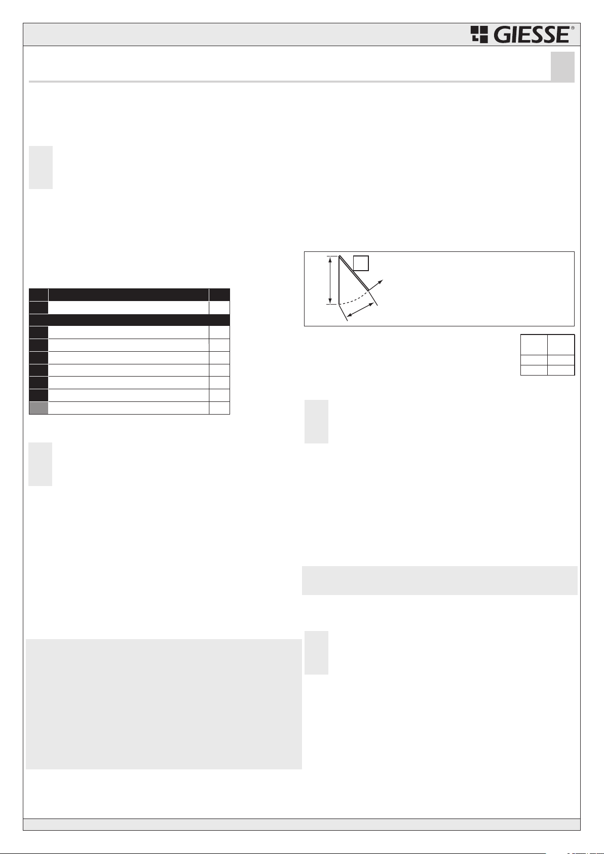
F
H
P
C
H = Höhe fensterflügel (mm)
P = Gewicht des flügels (Kg)
C = Kettenhub (mm)
F = zur öffnung erforderliche kraft (N)
F= P/2 x C/H x 10
Anwendungsbereich
Der Antrieb VARIA LUX ist ausschließlich zum Öffnen und zum Schließen von
Kipp-, Klapp- und Schwingfenstern sowie Dachoberlichtern bestimmt.
Ein davon abweichender Einsatz ist von GIESSE nach vorheriger technischer
Prüfung der Anwendung zu genehmigen.
Produktbeschreibung
Es handelt sich um einen elektrischen Kettenantrieb, bei dem die
Kette in einem Gehäuse aufgerollt wird. Er eignet sich für
Klappfenster und Dachoberlichtern ab einer Höhe von 50 cm.
Der Betrieb des Systems erfolgt bei einer Spannung von 230 Volt Ws.
Die Hübe können eingestellt werden.
Das Modell VARIA LUX ist mit einem Mikroendschalter, mit einer abziehbaren
Klemmleiste und mit einer Kontrolleuchte zur Anzeige der Schließstellung
des Fensters (Pos.9-Abb.1) ausgestattet. Zur Ausstattung gehören ferner
Bohrschablonen zur Montage an das Fenster. Die Antriebskette ist behandelt,
und ist dadurch auch bei schwierigsten Einsatzbedingungen mit einem
zuverlässigen Rostschutz ausgestattet.
Technische Daten
Siehe Tab. A.
Bestandteile
Jede VARIA LUX Packung enthält folgenden Inhalt (Abb. 1):
Installation
●Die Installation muß vom spezialisierten Fachmann ausgeführt
werden.
●Die Montage muß bei geschlossenem Fenster erfolgen.
●Die Spannungsversorgung muß während der Installation getrennt
sein.
●Sicherstellen, daß die verwendeten Lager bzw.
Beschläge den gesamten Öffnungshub des Antriebs zulassen.
Andernfalls könnten die Beschläge durch die Druck- bzw. Zugkraft des
Antriebs beschädigt werden.
a. Die Mittellinie des Fensters anzeichnen. Den Antrieb wie bei Abb.3-Pos.B
dargestellt posizionieren.
Achtung: Der Antrieb muss parallel zum Fesnster sein.
b. Die Bohrloecher mittels der 4 an der Befestigungsplatte des Antriebs
angebrachten Loecher ausfuehren (Abb.3-Pos.C).
c. Falls notwendig den Hub der Kette wie in den entsprechen Abschnitten
beschrieben veraendern.
d. Den Antrieb mittels passender Schrauben befestigen (Abb.3-Pos.C)
Hubeinstellung am Nocken
Hinweis: muß die Einstellung des Hubs vor der Installation erfolgen.
Der Antrieb wird mit der max. Hubeinstellung von 320 mm geliefert.
Zur Reduzierung des Kettenhubs wie folgt vorgehen: elektrischen Anschluß
vornehmen (siehe Paragraph 3), oder das Antriebsabnahmekabel (Code
04793000) verwenden. Danach:
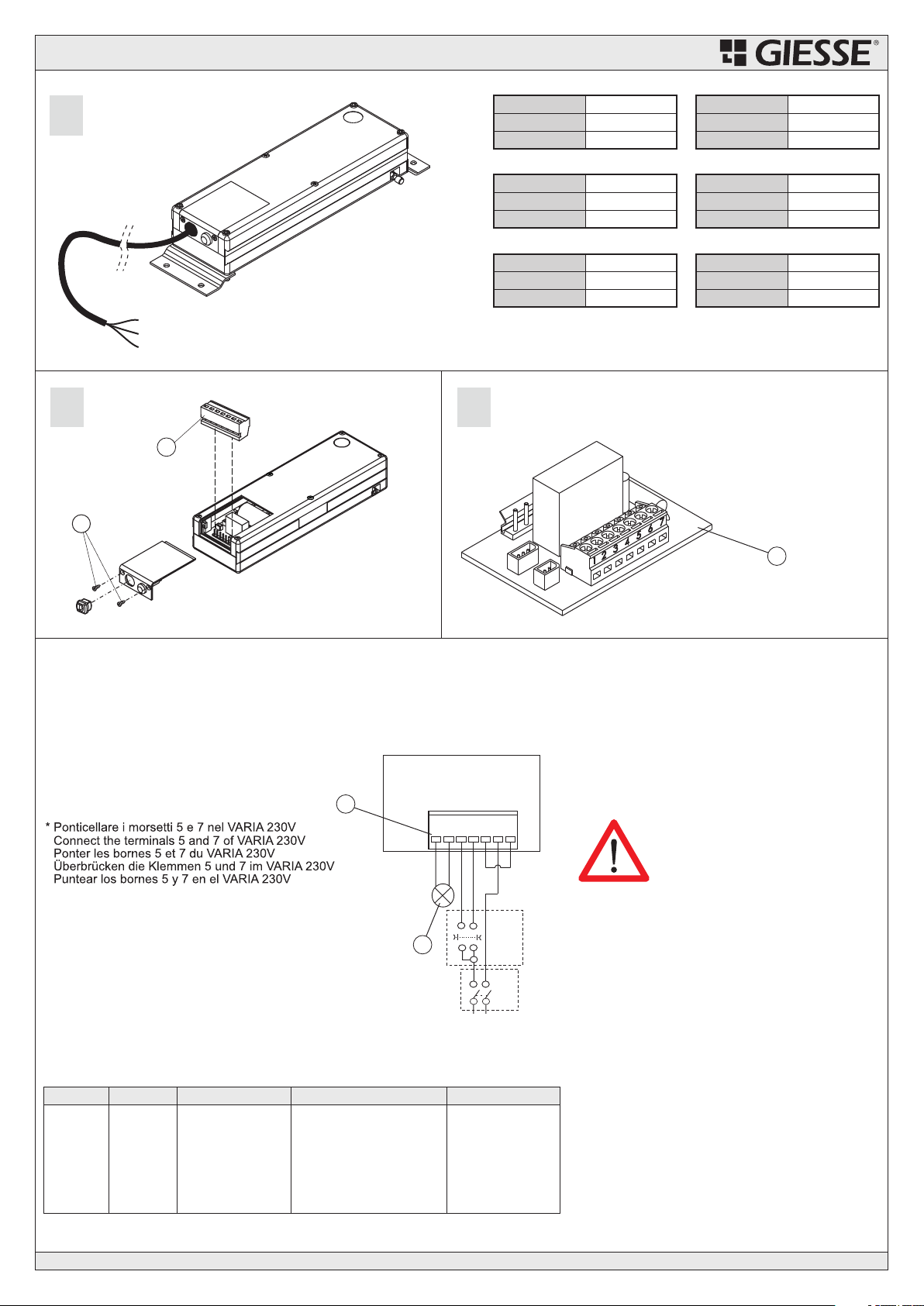
1. Die Abdeckung öffnen (siehe Abb.2-Pos.8).
2. Den Antrieb mit Spannung versorgen, Die Kette um eine gewisse Länge A,
entsprechend des gewünschten Hubs C, herausfahren; siehe Tab. B.
Beispiel: Bei Kette A=0 beträgt der Hub 90 mm.
3. Den mitgelieferten Einsatz zur Hubeinstellung (siehe Abb.2-Pos.7)
einsetzen.
4. Die Abdeckung wieder schließen.
e. Das Fenster schließen und dabei so stark drücken, daß gewährleistet ist,
daß die Dichtungen abdichten. Danach den vorderen Kettenstift (Abb.3-
Pos.4), komplett mit Mutter und Zahnscheibe festschrauben (Abb.3-
Pos.3) und die Position in Übereinstimmung mit dem Bügel einstellen.
f. Den Antrieb mit dem (Abb.3-Pos.5). Sicherstellen, daß
der Antrieb die Ansprechpositionen des Endschalters ohne Hindernisse
erreicht.
Der korrekte Verschluss des Beschlags und der Halt des Motors werden
durch das Aufleuchten der roten Kontrolllampe (9) angezeigt.
Hinweis: Der Antrieb wird in der Position Endschalter geschlossen geliefert.
ACHTUNG! Es ist wichtig den vorderen Stift mit der Mutter und Zahnscheibe
sichern (Abb.3-Pos.3).
Eventuelle Begrenzung des Laufwegs des Klappfensters
Die Werte H, P und C des Fensters ermitteln.
Die zum Bewegen des Flügels erforderliche Kraft F nach der nebenstehenden
Formel berechnen.
Befestigungsfeder
Der berechnete Wert F muss gleich oder kleiner sein als der
nebenstehende Tabellenwert für den zur Berechnung
verwendeten Kettenhub ©.
Wenn der Wert F größer ist, muss der Kettenhub (C) verkürzt
werden, bis ein akzeptabler Wert erreicht ist.
Hinweis: Der Kettenhub kann auch auf Werte zwischen den
in Tabelle angegebenen eingestellt werden.
Elektroanschluß
Achtung: Es besteht Verletzungs- und Lebensgefahr durch
Stromschlag.
Vor dem Anschluß ist die Spannungsversorgung zu unterbrechen.
Warnung: Dem Steuerkreis des Antriebs ist stets ein allpoliger
Hauptschalter mit einer Mindestkontaktöffnung von 3 mm mit einem
Schaltvermögen von 0,030 A vorzuschalten. Den exakten Querschnitt der
Versorgungskabel ermitteln, da für diese Kabel, auf der Grundlage der
Stromaufnahme des Antriebs, der richtige Querschnitt gewählt werden muß.
Stromkabel mit normalem Gummimantel, Durchmesser 7,9 mm
(Bezeichnung 60245 IEC 53).
Die beiden Schrauben (Abb.6-Pos.a) lösen.
Den Stromanschluß gemäß Abb.8 vornehmen.
Die Klemmen dürfen nicht für den Anschluss der biegsamen Kabel mit
Unterlegscheibe verwendet werden, es sei denn, die Enden der Leiter sind mit
einer Vorrichtung für die Verwendung von Schraubklemmen versehen.
Sicherstellen, daß die elektrischen Anschlüsse den einschlägigen
Vorschriften entsprechen.
HINWEIS: Zur Sicherheit der Anlage wird empfohlen, einen nicht rastenden
Taster zu verwenden (Totmannschaltung), oder die Versorgung, gemäß der
für die Betätigung nötigen Zeit, zu takten.
Auf dem Betätigungstaster muss die Stellung geöffnet/geschlossen
angegeben sein. Der Betätigungstaster ist nicht im Lieferumfang
inbegriffen.
Wartung
Einmal jährlich den Zustand der Lager, die Befestigung am Fenster
und den allgemeinen Zustand des Fensters prüfen. Zur
Gewährleistung eines einwandfreien Betriebs wird ferner empfohlen
die Kette mit Silikonspray einzufetten. Eventuell verschlissene Teile
austauschen.
Ferner sollte die Anlage in regelmäßigen Abständen (mindestens einmal
jährlich; bei Spezialanlagen mindestens einmal halbjährlich) überprüft
werden.
Hinweis: Die Wartung von Fachpersonal ausführen lassen.
250
300
200
150
C
(mm)
F
(N)
VARIA UNI LUX
Antrieb
Selbstschneidende Schrauben 4,8x13
UNI 6954
Sechskantmutter mit gezahnter
Unterlegscheibe
Vorderer Kettenstift
Befestigungsfeder
Fensteranschluss
Einsatz zur Hubeinstellung
Handbuch
1
2
1
1
1
1
1
1
Anz.Pos.
Zubehörs Packungsinhalt
1
2
3
4
5
6
7
Beschreibung
Empfehlungen und Sicherheitsnormen:
- Hinweis: Das System wurde bei geöffnetem Fensterflügel für eine maximale Windgeschwindigkeit von 40 km/Stunde getestet. Es wird daher der
Anschluss an eine Regen-/Windkontrolleinheit (Pv1) und die Installation eines Windstärkemessers empfohlen.
- Es wird empfohlen die GIESSE-Produkte vom Fachmann installieren zu lassen, der in der Lage ist eine angemessene technische Kompetenz zu
gewährleisten.
- Alle Eingriffe sind gemäß Herstellerhinweisen auszuführen.
- Der Installateur muß die Installation und die korrekte Funktion der Anlage prüfen.
- Der unsachgemäße Gebrauch bzw. ein nicht vom Hersteller vorgesehener Gebrauch der Anlage ist verboten.
- Originalersatzteile verwenden.
- Die “Totmannschaltung” verwenden, falls das Fenster auf einer Höhe von weniger als 2,5 m vom Boden angeordnet ist.
Hinweise für die Montage:
- Sicherstellen, daß die Lager und Beschläge des Fensters den kompletten Öffnungshub des Antriebs zulassen. Andernfalls könnten Schäden an den
genannten Teilen oder am Antrieb entstehen.
- Ein Klebeschild mit der Aufschrift “ACHTUNG, TEILE IN BEWEGUNG” muß neben der Einfassung angebracht werden.
- Es besteht Quetsch bzw. Einzugsgefahr! Der Antrieb hat eine Zug- und Druckkraft von 300N/150N. Die Befestigungen und Befestigungsstellen des
Zubehörs müssen diesen Kräften standhalten.
- Das Fenster muß mit angemessenen Stützen und Sicherheitssystemen ausgestattet sein. Der Antrieb kann nicht als dergleichen betrachtet werden.
- Die Kette nicht berühren, wenn sie in Bewegung ist.
- Das sich in Bewegung befindliche Fenster weder berühren, noch in dessen Bewegungsradius greifen.
- Achtung: Das Fenster muß mit auf das Gewicht abgestimmten Sicherheitsscheren ausgestattet sein.
- Während der Installation und der Wartung muß die Spannungsversorgung getrennt werden.