GETTING STARTED
NI SMD-7611/7612 Stepper Drives
and NI 9512 C Series Modules
Note If you are a new user of LabVIEW or are unfamiliar with LabVIEW, refer to
the Getting Started with LabVIEW manual for information about LabVIEW and
LabVIEW terminology.
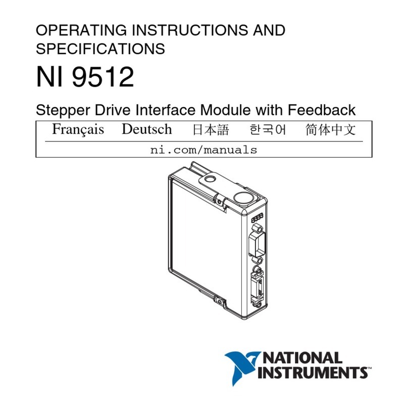
This document explains how to install and configure the NI SMD-7611/7612 stepper drives for
use with the NI 9512 C Series drive interface module.
Contents
What You Need to Get Started ................................................................................................. 2
Hardware .......................................................................................................................... 2
Software............................................................................................................................ 2
Related Documentation .................................................................................................... 3
Hardware Installation and Configuration ................................................................................. 4
Step 1: Set Up the CompactRIO System .......................................................................... 4
Step 2: Connect the NI 9512 to the 37-Pin Terminal Block............................................. 5
Step 3: Connect the 37-Pin Terminal Block to the +24 V Power Supply ........................ 6
Step 4: Connect the Drive Command Signals .................................................................. 6
Step 5: Connect the Drive Enable Signal ......................................................................... 7
Step 6: (Optional) Connect the Drive Fault Signal........................................................... 7
Step 7: (Optional) Connect the Encoder Signals .............................................................. 7
Step 8: Connect the NI PS-12/13 Power Supply to the NI SMD-7611/7612................... 8
Step 9: Connect the SMD-7611/7612 to the Motor.......................................................... 9
Step 10: Configure the NI SMD-7611/7612 DIP Switches.............................................. 10
Step 11: Set the Motor Selection Switch .......................................................................... 11
Step 12: Power on the Drive and Verify Connections...................................................... 13
Software Installation and Configuration................................................................................... 14
Step 1: Install Software on and Configure the NI RT Controller..................................... 14
Step 2: Create a Project in Scan Interface Mode .............................................................. 15
Step 3: Add Resources to the Project ............................................................................... 16
Step 4: Configure the NI 9512 Axis ................................................................................. 18
Step 5: Enable and Test the Drive Using LabVIEW ........................................................ 21
Worldwide Support and Services ............................................................................................. 22
