Giga-tronics 2400 series Owner's manual

Giga-tronics 2400 and 2500 Series Microwave Signal Generators
Programming Manual, Part Number 347 3, Rev A, July 2009
Programming Manual
2400 and 2500 Series
Microwave Signal Generators

Giga-tronics 2400 and 2500 Series Microwave Signal Generators
Programming Manual, Part Number 347 3, Rev A, July 2009
All technical data and specifications in this publication are subject to change without prior notice and do
not represent a commitment on the part of Giga-tronics, Incorporated.
© 2009 Giga-tronics Incorporated. All rights reserved. Printed in the U.S.A.
CONTACT INFORMATION
Giga-tronics, Incorporated
4650 Norris Canyon Road
San Ramon, California 945 3
Telephone: 00.726.4442 (only within the United States)
925.32 .4650
Fax: 925.32 .4700
On the Internet: www.gigatronics.com
Warranty
Giga-
tronics 2400/2500 Series instruments are warranted
against defective materials a
nd workmanship for one year from
date of shipment. Giga-
tronics will at its option repair or replace
products that are proven defective during the warranty period.
This warranty DOES NOT cover damage resulting from improper
use, nor workmanship other than Giga-
tronics service. There is
no implied warranty of fitness for a particular purpose, nor is
Giga-
tronics liable for any consequential damages. Specification
and price change privileges are reserved by Giga-tronics.

Giga-tronics 2400 and 2500 Series Microwave Signal Generators
Programming Manual, Part Number 347 3, Rev A, July 2009
Regulatory Compliance Information
This product complies with the essential requirements of the following applicable European
Directives, and carries the CE mark accordingly.
8 /336/EEC and 73/23/EEC EMC Directive and Low Voltage Directive
EN61010-1 (1 3) Electrical Safety
EN61326-1 (1 7) EMC – Emissions and Immunity
Manufacturer’s Name: Manufacturer’s Address
Giga-tronics, Incorporated 4650 Norris Canyon Road
San Ramon, California 4583
U.S.A.
Type of Equipment: Model Series Number
Microwave Signal Generator 2400 Series
2500 Series
Model Numbers:
2408C, 2420C, 2426C,
2440C
2508B, 2520B, 2526B,
2540B, 2550B
Declaration of Conformity on file. Contact Giga-tronics at the follo ing;
Giga-tronics, Incorporated
4650 Norris Canyon Road
San Ramon, California 945 3
Telephone: 00.726.4442 (only within the United States)
925.32 .4650
Fax: 925.32 .4700

Giga-tronics 2400 and 2500 Series Microwave Signal Generators
Programming Manual, Part Number 347 3, Rev A, July 2009
Record of changes to this Manual
Use the table below to maintain a permanent record of changes to this document. Replacement pages
will be issued as a TPCI (Technical Publication Change Instruction), and will be inserted at the front of
the binder. Remove the corresponding old pages, insert the new pages, and record the changes here. Do
the same thing with TCPI pages that are issued after you have received this manual.
TPCI Number TPCI Issue Date Date Entered Comments

Giga-tronics 2400 and 2500 Series Microwave Signal Generators
Programming Manual, Part Number 347 3, Rev A, July 2009 i
Table of Contents
Table of Contents........................................................................................................................................... i
Chapter 1. Safety ....................................................................................................................................1
1.1 Unsafe Operating Conditions........................................................................................................1
1.2 Safety Warnings Used in This Manual ..........................................................................................1
1.2.1 Personal Safety Alert.............................................................................................................1
1.2.2 Equipment Safety Alert.........................................................................................................1
1.2.3 Notes.....................................................................................................................................1
Chapter 2. Introduction ..........................................................................................................................3
2.1 Overview .......................................................................................................................................3
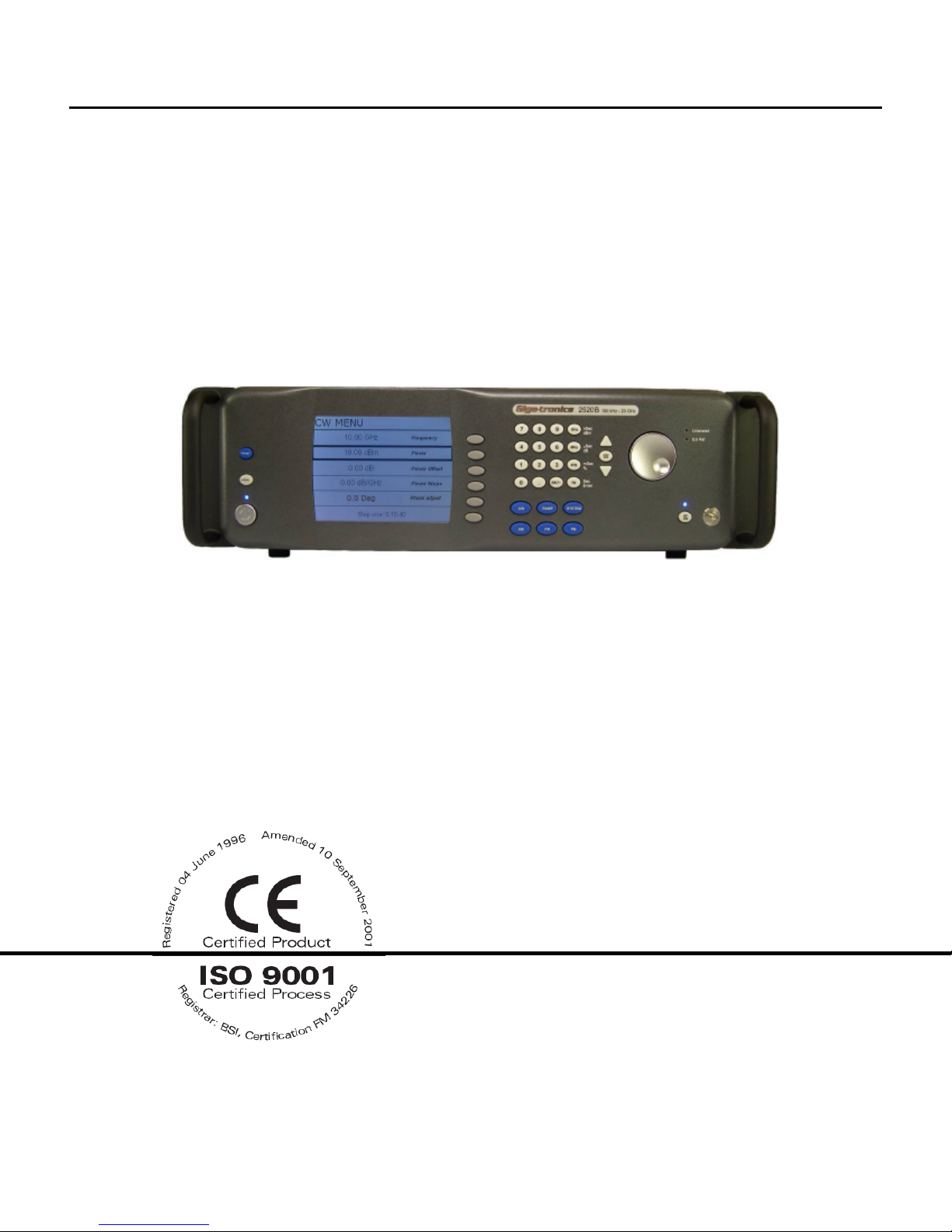
2.2 Physical Description of the 2400/2500.........................................................................................4
Chapter 3. Hardware Interfaces .............................................................................................................5
3.1 Introduction ..................................................................................................................................5
3.2 Configure the 2400/2500 Hardware Interface .............................................................................6
3.2.1 Using the Included USB Cable...............................................................................................6
3.2.2 Assign a GPIB Address to the 2400/2500..............................................................................6
3.2.3 Configure the Computer’s RS-232 for Remote Operation....................................................6
3.2.4 Configure the 2400/2500 Ethernet Connection ...................................................................7
Chapter 4. Programming Interfaces .......................................................................................................9
4.1 Introduction ..................................................................................................................................9
4.2 Select the Remote Programming Language..................................................................................9
4.3 Dynamic Link Library (DLL)..........................................................................................................10
4.3.1 Adding the DLL to Programming Projects...........................................................................10
4.3.2 Programming Examples Using the DLL ...............................................................................11
4.3.3 DLL Functions ......................................................................................................................17
4.4 SCPI Command Set......................................................................................................................96
4.4.1 SCPI Command Format .......................................................................................................96
4.4.2 SCPI Commands ..................................................................................................................97
4.5 IEEE 4 .2 Common Commands...............................................................................................120
4.6 GT-12000 Native Commands ....................................................................................................122
4.6.1 GT-12000 Native Commands: CW and System.................................................................122
4.6.2 GT-12000 Native Commands: List Mode ..........................................................................123
4.6.3 GT-12000 Native Commands: Amplitude Modulation .....................................................125
4.6.4 GT-12000 Native Commands: Frequency Modulation .....................................................126
4.6.5 GT-12000 Native Commands: Phase Modulation.............................................................127
4.6.6 GT-12000 Native Commands: Pulse Modulation..............................................................12
4.7 Emulation..................................................................................................................................129
4.7.1 HP 34X Emulation Commands ........................................................................................129

Giga-tronics 2400 and 2500 Series Microwave Signal Generators
ii Programming Manual, Part Number 347 3, Rev A, July 2009
4.7.2 HP 663 Emulation Commands ........................................................................................132
4.7.3 HP 673 Emulation Commands ........................................................................................134
4.7.4 HP 360 Emulation Commands ........................................................................................13
4.7.5 HP 370 Emulation Commands ........................................................................................139
4.7.6 GT900 Emulation Commands ...........................................................................................140
4.7.7 Option 55F: Wavetek 90X Emulation Commands.............................................................142
4.7. Systron Donner 16XX Emulation Commands....................................................................143
Chapter 5. Automation Xpress............................................................................................................149
5.1 Introduction ..............................................................................................................................149
5.1.1 Benefits of Using Automation Xpress ...............................................................................149
5.2 Install Automation Xpress.........................................................................................................150
5.3 Start Automation Xpress...........................................................................................................152
5.4 Automation Xpress GUI Description .........................................................................................154
5.4.1 Tool Bar .............................................................................................................................155
5.4.2 Indicators and RF Button...................................................................................................165
5.5 Auto Programmer .....................................................................................................................167
5.5.1 Introduction ......................................................................................................................167
5.5.2 Auto Programmer Examples .............................................................................................16
Chapter 6. Status Register System......................................................................................................171
6.1 Introduction ..............................................................................................................................171
6.2 Status Byte and Service Request Enable Registers ...................................................................173
6.3 Standard Event Status and Standard Event Status Enable Registers........................................174
6.4 Questionable Status Condition and Enable Registers...............................................................175
Chapter 7. 2400/2500 Specific Commands ........................................................................................177
Chapter . List Mode Operation .........................................................................................................179
Chapter 9. LabVIEW Drivers................................................................................................................1 1
9.1 Overview ...................................................................................................................................1 1
9.2 LabVIEW Drivers........................................................................................................................1 3
9.2.1 LabVIEW Drivers for DLL Functions...................................................................................1 3
9.2.2 Non-DLL LabVIEW Drivers.................................................................................................1 7
Appendix A. Remote Error Messages....................................................................................................1 9
Appendix B. DLL Error Messages...........................................................................................................193
Appendix C. FM Sensitivity/Deviation RangeTable ...............................................................................197

Giga-tronics 2400 and 2500 Series Microwave Signal Generators 1. Safety
Programming Manual, Part umber 34783, Rev A, July 2009 1
Chapter 1. Safety
1.1 Unsafe Operating Conditions
If you notice any of the following conditions while operating electronics equipment, IMMEDIATELY
de-energize the equipment.
• The instrument fails to operate normally, or operates erratically.
• The power cable, receptacle, or plug on the instrument is damaged
• The instrument causes electrical shock or operates at abnormally high temperature.
• A liquid or foreign substance falls into the instrument
• The instrument generates an abnormal sound, smell, smoke, or sparking light.
If any of the above conditions occurs, contact Giga-tronics to get the instrument repaired.
Continuing to operate the instrument with any of the above conditions could
cause death or serious damage to the instrument and any equipment connected to it.
1.2 Safety Warnings Used in This Manual
1.2.1 Personal Safety Alert
WARNING: Indicates a hazardous situation which, if not avoided, could result in
death or serious injury.
1.2.2 Equip ent Safety Alert
CAUTION: Indicates a situation which can damage or adversely affect the 2400 and 2500
or associated equipment.
1.2.3 Notes
otes are denoted and used as follows:
NOTE: Highlights or amplifies an essential operating or maintenance procedure, practice,
condition or statement.
WARNING
!
WARNING
!
CAUTION

1. Safety Giga-tronics 2400 and 2500 Series Microwave Signal Generators
2 Programming Manual, Part umber 34783, Rev A, July 2009
This page is intentionally blank

Giga-tronics 2400 and 2500 Series Microwave Signal Generators 2. Introduction
Programming Manual, Part Number 478 , Rev A, July 2009
Chapter 2. Introduction
2.1 Overview
Manual Convention:
• For simplicity, when generically referring to Giga-tronics Microwave Signal Generators in the
2400 and 2500 Series, the term “2400 2500” may be used. Specific models within either series
are referred to when necessary.
This manual describes how to program and remotely control the 2400/2500 and 2500B Series
Microwave Signal Generators for automated testing.
Giga-tronics designed the 2400/2500 for high performance and flexibility, and accordingly, there are
different ways to set up the instrument for automated testing. All methods for setting up the 2400/2500
for automated testing are described in this manual.
However, the easiest and most effective way to use the 2400/2500 for automated testing is through
Automation Xpress, an automated testing application developed by Giga-tronics that is included on the
CD-ROM that shipped with the 2400/2500.
Automation Xpress provides the fastest switching of power and frequency during automated testing.
This maximizes device throughput, keeping your testing costs as low as possible.
Features of Automation Xpress:
• 1.0 ms frequency and power switching during testing
• Eliminate the need to learn GPIB or other native language commands by using the Auto
Programming feature, which automatically records a sequence of actions and converts those
actions into program code. You can then import this code into the program environment of your
choice, such as Visual C++ or Visual Basic.
• The Xpress Auto-programming feature virtually eliminates training time by providing scripts and
sequences guaranteed for accuracy.
• Transit and execution times for single-function calls such as changing CW frequency are ten
times faster using Automation Xpress compared to standard message-based commands.
• Automation Xpress sends large amounts of data (i.e., large lists) more than 100 times faster than
SCPI commands.

2. Introduction Giga-tronics 2400 and 2500 Series Microwave Signal Generators
4 Programming Manual, Part Number 478 , Rev A, July 2009
2.2 Physical Description of the 2400/2500
If you need information about the controls, indicators, display, or any other physical aspects of the
2400/2500, refer to the Operation Manual for the series you are interested in:
2400/2500 Operation Manual part number: 4802
2500B Operation Manual part number: 47 7

Giga-tronics 2400/2500 Series Microwave Signal Generators 3. Hardware Interfaces
Programming Man al, Part N mber 34783, Rev A, J ly 2009 5
Chapter 3. Hardware Interfaces
3.1 Introduction
The 2400/2500 has fo r connectors to choose from for connecting to a comp ter:
• GPIB
• LAN (Ethernet)
• RS-232
• USB
Fig re 1 below shows the locations of the connectors on the 2400/2500 rear panel. Descriptions of the
connectors are given in Table 1 below.
NOTE: Yo r 2400/2500 may look slightly different, depending on series and model.
Figure 1. 2400/2500 Rear Panel
Table 1 2400/2500 Hardware Interfaces Descripti n
Name Descripti n
GPIB A 24-pin IEEE STD 488.2 connector for control of the instr ment d ring remote
operation sing GPIB.
RS-232 A DB-9 connector for control of the instr ment d ring remote operation sing
RS-232 serial comm nications. A USB to Serial Cable Port Adapter is incl ded
with the 2400/2500 for controlling the instr ment via the USB port on a host
comp ter.
USB A USB connector for control of the instr ment d ring remote operation sing
USB 2.0 (f ll speed) comm nications
Ethernet An Ethernet connector for control of the instr ment d ring remote operation
sing LAN interface comm nications.
GPIB
RS
-
232
USB
LAN

3. Hardware Interfaces Giga-tronics 2400/2500 Series Microwave Signal Generators
6 Programming Man al, Part N mber 34783, Rev A, J ly 2009
3.2 Configure the 2400/2500 Hardware Interface
3.2.1 Using the Included USB Ca le
A USB 2.0 Type A Male to Type B Male cable shipped with the 2400/2500, and provides yo with the
simplest way to connect a comp ter to the 2400/2500. The cable connects between a USB port on the
comp ter, and the USB port on the 2400/2500.
To se this cable, yo m st first install A tomation Xpress and the USB driver on the comp ter. See
Table 40 on page 150.
3.2.2 Assign a GPIB Address to the 2400/2500
To connect a comp ter to the 2400/2500 via GPIB, the 2400/2500 m st be assigned a GPIB address. The
proced re below describes how to assign a GPIB address to a 2400/2500.
Table 2 Setup GPIB Address
Step Acti n
1.
On the front panel of the 2400/2500, press to display the System men s, and if the
SYSTEM 2 men does not appear in the display, press the bottom-most interactive softkey ntil it
does.
2.
Enter the desired GPIB address sing either the n meric keypad or .
End f Pr cedure
3.2.3 Configure the Computer’s RS-232 for Remote Operation
Table 3 below gives information for config ring an RS-232 port on a comp ter to comm nicate with the
2400/2500.
Table 3 RS-232 C mmunicati n Settings
Ba d rate 115200
Data Bits 8
Parity None
Stop bits 1
Handshake None
SYSTEM

Giga-tronics 2400/2500 Series Microwave Signal Generators 3. Hardware Interfaces
Programming Man al, Part N mber 34783, Rev A, J ly 2009 7
3.2.4 Configure the 2400/2500 Ethernet Connection
The following proced re explains how to set the DHCP, IP Address, and S bnet Mask of the 2400/2500
when sing the Ethernet (LAN) connector on the rear of the 2400/2500. The instr ment is identified via
Ethernet connection d ring remote operations sing the IP address set in this proced re. Each nit on
the network m st have a niq e IP address.
Table 4 C nfigure Rem te Operati n Using the LAN
Step Acti n
1.
Press to invoke the System men s, and if the SYSTEM 4 men does not appear in
the display, press the bottom-most interactive softkey ntil it does.
2.
Are yo going to connect the LAN sing Dynamic Host Config ration Protocol (DHCP), or
config re the LAN connection man ally?
If the LAN c nnecti n will be d ne by DHCP: go to the next step.
If the LAN c nnecti n will be c nfigured manually: go to Step 4.
3.
Press the DHCP softkey and set DCHP to On sing the keys. The instr ment will try to
connect to the DCHP server and the IP address and S bnet Mask will be set a tomatically from
the first server that establishes comm nication via the LAN connection.
Go to Step 7.
NOTE: If the 2400/2500 fails to connect to the DCHP server, the nit will attempt to reconnect
again. If it fails to connect to the DCHP server a second time, the 2400/2500 will attempt to
reconnect once every ho r. D ring this period, the IP address and s bnet mask val es will be
zero.
4.
Press the DHCP softkey and set DCHP to Off sing the keys.
5.
Press the IP Address softkey to highlight the IP Address men item. Enter the IP address sing the
n meric keypad.
NOTE: An IP address consists of fo r sets of three-digit n mbers, separated by decimal points.
The following example demonstrates how to properly enter an IP address:
190.165.001.034
An invalid IP entry will be displayed as Invalid IP Inp t in the Step Size/Error Message section of
the display. Examples of invalid addresses are val es greater than 255, less than zero (negative
sign), val es greater than three digits per set or more or less than 4 sets of three-digit val es.
6.
Press the S bnet Mask softkey to highlight the S bnet Mask men item. Enter the s bnet mask
n mber sing the seq ence defined in the previo s step.
7.
Confirm that the server has connected to 2400/2500 by observing the Link Stat s men item.
This men item is an indicator only. No entry key f nctions are processed.
End f Pr cedure
SYSTEM

3. Hardware Interfaces Giga-tronics 2400/2500 Series Microwave Signal Generators
8 Programming Man al, Part N mber 34783, Rev A, J ly 2009
This page is intenti nally blank

Giga-tronics 2400/2500 Microwave Synthesizer Series 4. Programming Interfaces
Programming Manua , Part Number 34783, Rev A, Ju y 2009 9
Chapter 4. Programming Interfaces
4.1 Introduction
This chapter describes the different programming interfaces and methods for remote y contro ing a
2400/2500.
4.2 Select the Remote Programming Language
The 2400/2500 can communicate using a variety of anguages. Every 2400/2500 is capab e of
communications using the SCPI (Standard Commands for Programmab e Instruments) anguage or any
Giga-tronics native command set. Optiona Command Sets are avai ab e as we .
Tab e 5 be ow describes how to use the 2400/2500 front pane in oca operating mode to se ect a
anguage from the Language Menu.
Table 5 Select the Remote Language
Step Action
1.
• If the instrument IS NOT in remote operating mode, press the LOCAL button once to invoke
the Language menus in the disp ay.
• If the instrument IS IN remote operating mode, press the LOCAL button twice - once to take
it out of remote operating mode, then again to invoke the Language menus in the disp ay.
2.
If the desired anguage does not appear in the parameter area of the disp ay, press the bottom-
most interactive softkey to go to the next menu. There are three screens for the Language
menus. Use the bottom softkey to go through the screens unti you find the anguage you want
to use.
3.
If the message “Option not insta ed” appears next to a given anguage in the menu area of the
disp ay, that anguage is optiona and not current y avai ab e in the instrument. Contact Giga-
tronics customer support to inquire about purchasing additiona anguage options.
4.
Once you have ocated the desired anguage, press the associated interactive softkey in the
disp ay to se ect it.
End of Procedure

4. Programming Interfaces Giga-tronics 2400/2500 Microwave Synthesizer Series
10 Programming Manua , Part Number 34783, Rev A, Ju y 2009
4.3 Dynamic Link Library (DLL)
A DLL is a co ection of routines that can be used by app ications or other DLLs. A DLL is provided on the
CD-ROM that is inc uded with the 2400/2500 Microwave Signa Generator. When you insta Automation
Xpress from the CD-ROM onto your computer, the DLL is oaded onto your computer. The routines in
the DLL can be used in Visua C++, Visua Basic, and other app ications.
4.3.1 dding the DLL to Programming Projects
The fo owing procedures describe how to inc ude the DLL into Visua C++ and Visua Basic projects.
4.3.1.1 dd the DLL to a Visual C++ Project
Table 6 Add the DLL to a isual C++ Project
Step Action
1.
Create a Visua C++ project.
2.
Copy GT2400.d from C:\Program Fi es\Giga-tronics\AX\bin into your project’s executab e fo der
for run time ca s. (e.g. fo der named “Debug”)
3.
Copy GT2400. ib from C:\Program Fi es\Giga-tronics\AX\ ib into your project.
4.
Copy a fi es from C:\Program Fi es\Giga-tronics\AX\inc ude into your project.
5.
Copy the fo owing ine into your app ication C/C++ fi es:
“#inc ude “GT2400.h”
6.
Make DLL function ca s as needed from any .cpp fi es where GT2400.h fi e is inc uded.
7.
Bui d your app ication.
End of Procedure
4.3.1.2 dd the DLL to a Visual Basic Project
Table 7 Add the DLL to a isual Basic Project
Step Action
1.
Create a Visua Basic project.
2.
Copy GT2400.d from C:\Program Fi es\Giga-tronics\AX\bin into your project’s executab e fo der
for run time ca s.
3.
Copy DLLDec are.bas from C:\Program Fi es\Giga-tronics\AX\VBModu e to the project fo der.
4.
Make DLL function ca s as needed from any fi es in the project.
5.
Bui d the app ication.
End of Procedure

Giga-tronics 2400/2500 Microwave Synthesizer Series 4. Programming Interfaces
Programming Manua , Part Number 34783, Rev A, Ju y 2009 11
4.3.2 Programming Examples Using the DLL
4.3.2.1 CW Operation Using Visual C++
NOTE: On y bo d faced code ines are unique to a specific operation mode. A other ines are supporting
ines shared by both CW and List modes.
Step Description
1.
Perform steps 1 through 5 in Tab e 6 on page 10 to add the DLL to a Visua C++ project.
2.
Write the fo owing code:
#include "GT2400.h"
#include "stdio.h"
#define SUCCESS 0
//This routine sets CW frequency and power of a 2400/2500
synthesizer
//at your choice through GPIB at address 6.
void main(void)
{
STATUS status;
unsigned long instrumentHandle;
double Frequency =1000;
double Power =0;
status =GT2400_OpenConnection(0,6,0,&instrumentHandle);
if(status <SUCCESS )
{
char statusText[256];
GT2400_GetErrorMessage(status, statusText);
printf("Status Message %s\n",statusText);
}
status =GT2400_SetRF(instrumentHandle, 1);
printf("Frequency (MHz) =");
scanf("%lf",&Frequency);
printf("Power (dBm) =");
scanf("%lf",&Power);
status =GT2400_SetCW(instrumentHandle,Frequency,Power,0,0);
status =GT2400_CloseAllConnections();
}
3.
Bui d the project.
4.
Run the program.
End of Example

4. Programming Interfaces Giga-tronics 2400/2500 Microwave Synthesizer Series
12 Programming Manua , Part Number 34783, Rev A, Ju y 2009
4.3.2.2 Programming Example; CW Operation Using Visual Basic
Step Description
1.
Perform steps 1 through 3 of Tab e 7 on page 10 to create a Visua Basic project.
2.
Write the fo owing
‘This routine sets CW frequency and power of a 2400/2500
synthesizer
‘through GPIB at address 6.
Dim status As Long
Dim instrumentHandle As Long
Dim Frequency As Double
Dim Power As Double
Dim statusText As String
statusText = Space(100)
status =GT2400_OpenConnection(0,6,0,instrumentHandle)
If status <SUCCESS Then
GT2400_GetErrorMessage(status, statusText)
MsgBox statusText
End If
status =GT2400_SetRF(instrumentHandle, 1)
Frequency = 20000 ‘MHz
Power = 10
status =GT2400_SetCW(instrumentHandle,Frequency,Power,0,0)
status =GT2400_CloseAllConnections()
3.
Bui d the project.
4.
Run the program.
End of example

Giga-tronics 2400/2500 Microwave Synthesizer Series 4. Programming Interfaces
Programming Manua , Part Number 34783, Rev A, Ju y 2009 13
4.3.2.3 Programming Example; List Operation Using Visual C++
Step Description
1.
Perform steps 1 through 5 of Tab e 6 to create a Visua C++ project.
2.
Write the fo owing code:
#inc ude <windows.h>
#inc ude <stdio.h>
#inc ude "gt2400.h"
#define SUCCESS 0
//This routine can oad any ist fi e to 2400/2500 synthesizer
//and set up repeat type and trigger type at user choice.
void main(void)
{
ong status;
char istFi eName[80];
char statusText[256];
unsigned ong instrumentHand e;
short tmp;
status = GT2400_OpenConnection(0, 6, 0, &instrumentHand e);
if(status < SUCCESS )
{
GT2400_GetErrorMessage(status, statusText);
printf("Status Message %s\n",statusText);
}
printf("P ease enter the fi e name to be oaded:\n ");
scanf("%s",& istFi eName);
status = GT2400_LoadListFromFi e( istFi eName, statusText);
if ( status < SUCCESS ) //Error during oading
{
GT2400_GetErrorMessage(status, statusText);
printf("Status Message %s\n",statusText);
}
status = GT2400_Down oadList(instrumentHand e, istFi eName);
printf("Enter Repeat Type (0 = sing e step; 1 = sing e sweep; 2 = continuous) =");
scanf("%d",&tmp);
status = GT2400_SetRepeatType(instrumentHand e, tmp);
printf("Enter Trigger Type (0 = Externa trigger; 1 = Software trigger or GET) =");
scanf("%d",&tmp);
status = GT2400_SetTriggerType(instrumentHand e, tmp);
status = GT2400_SetRF(instrumentHand e, 1);
status = GT2400_C oseA Connections();
}
Continued next page

4. Programming Interfaces Giga-tronics 2400/2500 Microwave Synthesizer Series
14 Programming Manua , Part Number 34783, Rev A, Ju y 2009
Step Description
3.
Bui d the project.
4.
Run the program.
5.
Send trigger.
End of example
Other manuals for 2400 series
1
This manual suits for next models
10
Popular Inverter manuals by other brands

C.E. Nierhoff & Co
C.E. Nierhoff & Co C524 troubleshooting guide

sylber
sylber SOL R-7,5M Installation and maintenance manual

maximo
maximo PV2024 HM user manual

Base aire
Base aire O-UVC2 Pro Installation & operation manual

NEP
NEP BDM-300X2-240A-D Installation and operation manual

RND power
RND power RND 320-00134 user manual