Gigawave INCAM-G User manual

CABK-ASOM-735x-01
INCAM-G Operator’s Manual Page 1 of 25
The information contained in this manual remains the property of Gigawave and may not be used,
disclosed or reproduced in any other form whatsoever without the prior written permission of
Gigawave.
Gigawave reserves the right to alter the equipment and specification appertaining to the equipment
described in this manual without notification.
INCAM-G
Wireless Camera Transmitter
OPERATOR’S MANUAL
Copyright © 2014 Vislink International Limited

CABK-ASOM-735x-01
INCAM-G Operator’s Manual Page 2 of 25
CONTENTS
1 General information ................................................................................................................. 3
1.1 General Safety Information .............................................................................................. 3
1.2 Disposal Instructions ....................................................................................................... 3
1.3 Environmental ................................................................................................................. 3
1.4 Health & Safety................................................................................................................ 4
1.5 Maximum RF Power Density Limits ................................................................................. 5
1.6 Document Issue Status.................................................................................................... 5
2 Introduction ............................................................................................................................. 6
3 Specifications .......................................................................................................................... 8
4 Installing the INCAM-G onto the camera ............................................................................... 10
5 INCAM-G operation ............................................................................................................... 11
5.1 On / Standby / Off switch ............................................................................................... 11
5.2 Connectors and Pin outs ............................................................................................... 11
5.2.1 Rear Connectors........................................................................................................ 11
5.2.1.1 Telemetry Antenna (1) ....................................................................................... 11
5.2.1.2 Video Out (2) ..................................................................................................... 12
5.2.1.3 Power In (3) ....................................................................................................... 12
5.2.1.4 Power Switch (4) ................................................................................................ 12
5.2.1.5 Steadicam Tally (5) ............................................................................................ 12
5.2.1.6 Return Data (6) .................................................................................................. 12
5.2.1.7 External Audio (7) .............................................................................................. 12
5.2.1.8 Remote Configuration (8) ................................................................................... 13
5.2.1.9 RF Antenna (9) .................................................................................................. 13
5.2.2 Side Connectors ........................................................................................................ 14
5.2.2.1 Return In (1) ....................................................................................................... 14
5.2.2.2 SDI Out (2) ......................................................................................................... 14
5.2.3 Transmitter Configuration via Windows PC application .............................................. 15
6 Camera control ...................................................................................................................... 17
6.1 Associated documentation ............................................................................................. 17
6.2 Typical block diagrams .................................................................................................. 17
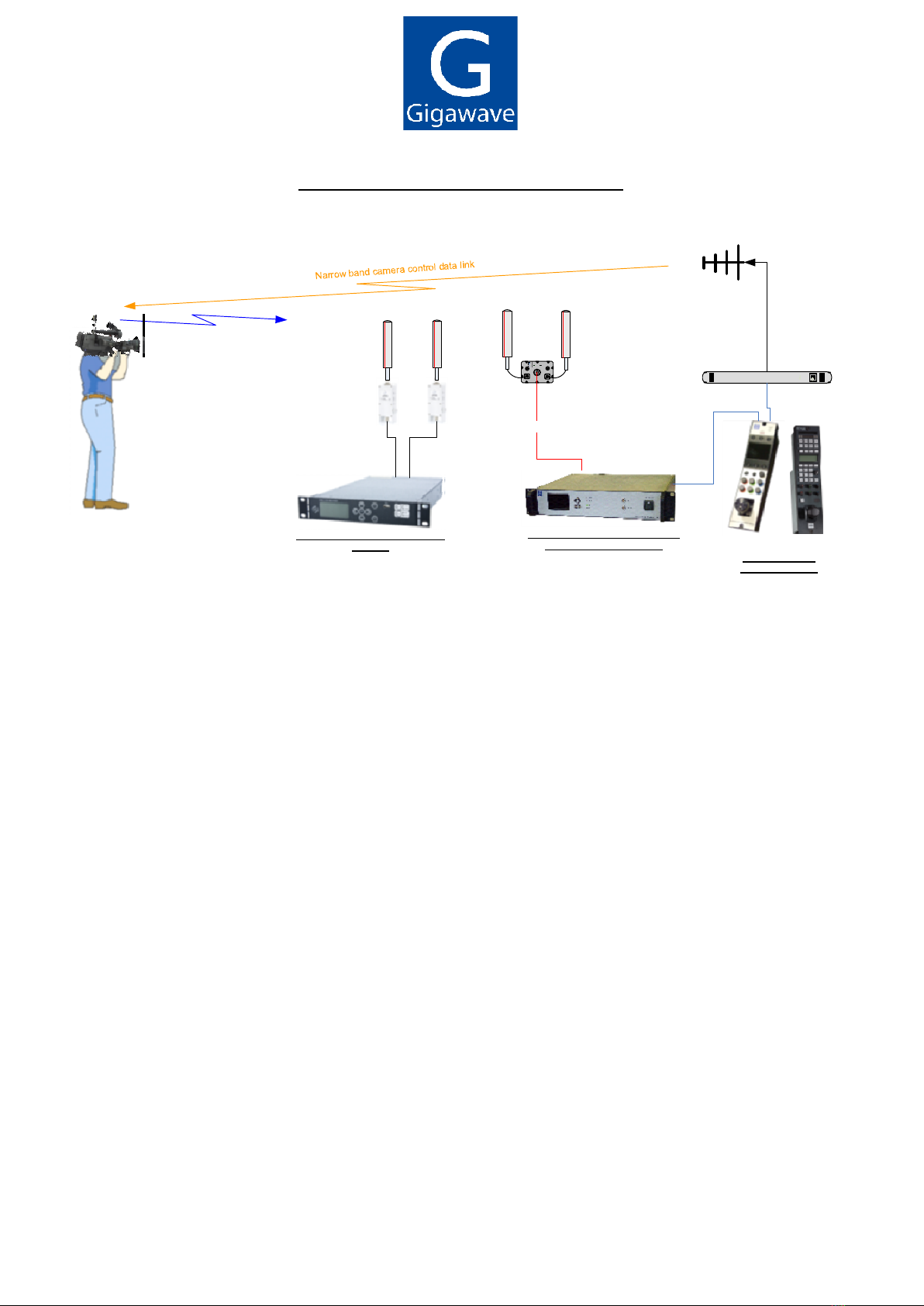
6.2.1 MVL-HD3 receiver with built in Camera control TX .................................................... 17
6.2.2 MVL-HD3 receiver with separate Camera control TX ................................................. 18
6.2.3 MTV-HD3 receiver ..................................................................................................... 19
6.2.4 Interconnection details, when Interface Unit............................................................... 20
6.2.5 Arrangement for multiple OCPs and Cameras, using a single Data TX ...................... 21
7 Preparing for operation .......................................................................................................... 22
7.1 The INCAM-G transmitter .............................................................................................. 22
7.2 The Receiving Equipment .............................................................................................. 22
8 Table of COFDM bit rates...................................................................................................... 23
8.1 DVB-T bit rates .............................................................................................................. 23
8.2 LMS-T Bit rates.............................................................................................................. 24
9 Internal Architecture Block Diagram ...................................................................................... 25

CABK-ASOM-735x-01
INCAM-G Operator’s Manual Page 3 of 25
1 General information
1.1 General Safety Information
The information that follows, together with local site regulations, must be studied by
personnel concerned with the operation or maintenance of the equipment, to ensure
awareness of potential hazards.
WARNING - RF Power Hazard : High levels of RF power are present in the unit. Exposure to RF
or microwave power can cause burns and may be harmful to health.
Switch off supplies before removing covers or disconnecting any RF cables, and before inspecting
damaged cables or antennas.
Avoid standing in front of high gain antennas (such as a dish) and never look into the open end of
a waveguide or cable where RF power may be present.
Users are strongly recommended to return any equipment that requires RF servicing to Gigawave.
WARNING - GaAs / BeO Hazard : Certain components inside the equipment contain Gallium
Arsenide and Beryllium Oxide that are toxic substances. Whilst safe to handle under normal
circumstances, individual components must not be cut, broken apart, incinerated or chemically
processed. In the case of Beryllium Oxide, a white ceramic material, the principal hazard is from
the dust or fumes, which are carcinogenic if ingested, inhaled or entering damaged skin.
Please consult your local authority before disposing of these components.
CAUTION - Tantalum Capacitors: When subjected to reverse or excess forward voltage, ripple
current or temperature these components may rupture and could potentially cause personal injury.
CAUTION: This system contains MOS devices. Electro-Static Discharge (ESD) precautions should
be employed to prevent accidental damage.
1.2 Disposal Instructions
All equipment, including batteries where applicable, should NOT be disposed of with household
waste as they are not bio-degradable in landfill sites. They should NOT be incinerated.
For safe disposal take to:
The local (council/authority) environmental waste site, (in Europe in accordance with the
European Environmental directive).
For details contact your local authority/recycling centre.
1.3 Environmental
The INCAM-G is IPxx rated and it must be protected from dripping or splashing water/fluids. When
installed in a camera and used outdoors the unit should be protected by the rain cover which is
normally used to protect the camera.

CABK-ASOM-735x-01
INCAM-G Operator’s Manual Page 4 of 25
1.4 Health & Safety
Exposure to Non Ionising (RF) Radiation/Safe Working Distances
The safe working distance from a transmitting antenna may be calculated from the relationship:
D =
in which D = safe working distance (meters)
PT = transmitter or combiner power output (watts)
GR = antenna gain ratio = anti log (gain dBi 10)
w = maximum allowed power density (watts/square meter)
The RF power density value is determined by reference to safety guidelines for exposure of the
human body to non-ionising radiation. It is important to note that the guidelines adopted differ
throughout the world and are from time-to-time re-issued with revised guidelines. For Gigawave
use, a maximum power density limit (w) of 1w/m² is to be applied when calculating minimum safe
working distances. Appendix A refers.
Important Note: It must be remembered that any transmitting equipment radiating power at
frequencies of 100 kHz and higher, has the potential to produce thermal and athermal effects upon
the human body.
To be safe:
a) Operators should not stand or walk in front of any antenna, nor should they allow anyone
else to do so.
b) Operators should not operate any RF transmitter or power amplifier with any of its covers
removed, nor should they allow anyone else to do so.
Worked examples
Antenna
Transmitter Power
Type
Gain (dBi)
Gain Ratio
2W
4W
10W
30W
OMNI
4 2.5 1 1 1.5 2.5
HELIX
20 100 4 5.6 9 15.5
PARABOLIC
DISH
35 3,162 22.5 32 50 87
MINIMUM SAFE DISTANCE (METRES)
PT. GR
4.w

CABK-ASOM-735x-01
INCAM-G Operator’s Manual Page 5 of 25
1.5 Maximum RF Power Density Limits
The RF Radiation Power Density limit figure recommended by Gigawave is based upon guideline
levels published in:
a. IEEE standard C95.1 1999 - IEEE Standard for Safety Levels with respect to Human
Exposure to Radio Frequency Electromagnetic Fields, 3 kHz to 300 GHz.
b. Guidelines for Limiting Exposure to Time-varying Electric, Magnetic & Electromagnetic
Fields (up to 300 GHz) published in 1998 by the Secretariat of the International Commission on
Non-Ionising Radiation Protection (ICNIRP).
Both documents define guideline RF power density limits for "Controlled" and "Uncontrolled"
environments. An uncontrolled environment is defined as one in which the person subjected to the
RF radiation may be unaware of and has no control over the radiation energy received. The
uncontrolled environment conditions can arise, even in the best regulated operations and for this
reason the limits defined for the uncontrolled environment have been assumed for the Gigawave
recommended limit.
Documents a) and b) also show the RF power density guidelines to be frequency dependent.
Different power density / frequency characteristics are presented in the two documents. To avoid
complexity and to avoid areas of uncertainty, Gigawave recommends the use of a single power
density limit across the frequency range 100 kHz to 300 GHz. The 1w/m² power density limit we
recommend satisfies the most stringent of the guidelines published to date.
Footnote: The IICNIRP document may be freely downloaded from the internet at
www.icnirp.de/emfgdl (PDF file), the IEEE standard is available on loan from Essex County Library
on payment of a search fee.
1.6 Document Issue Status
Issue
Date
Changes
1 11/12/2014 First issue

CABK-ASOM-735x-01
INCAM-G Operator’s Manual Page 6 of 25
2 Introduction
The INCAM-G is a Wireless Camera Transmitter built into the rear housing of the Grass Valley
LDX series cameras. The system includes a UHF data receiver unit for camera.
Features include:
Includes built in wireless camera control receiver module.
Full HD, 3G SDI
Superb and exclusive broadcast quality 1080p, 1080i, 720p H.264 encoding.
Ultra Low Delay down to 20ms H.264, plus Low and Standard Delay, with adjustable GOP (4
to 30).
Data rates up to 39Mbit/s,
Available for either COFDM DVB-T or LMS-T - factory options.
Linear distortion pre-correction of COFDM RF carrier for improved spectral re-growth and co-
channel performance (option).
Add on PA Barrel Booster option.
Camera control compatible with Grass Valley OCP 400 and Gigawave OCP5.
Control via USB connection with Windows™ PC Software
Fully compatible with Vislink’s Gigawave and Link receivers

CABK-ASOM-735x-01
INCAM-G Operator’s Manual Page 7 of 25
Typical INCAM-G system configurations
COFDM video link
triax
MVL-HD3 series 2/4 way diversity
Dual RF head, single triax
Choice of OCPs
OCP5 or OCP400
L2174 series 2 or 4 way diversity
receiver

CABK-ASOM-735x-01
INCAM-G Operator’s Manual Page 8 of 25
3 Specifications
Frequency bands 1.5 to 7GHz in bands
Tuning range 500MHz standard bandwidth.
1.95 to 2.7GHz factory option
Frequency Selection Up to 16 pre-set channels or tuning in 500kHz steps.
Transmit Power Switchable in steps 10 to 200mW (frequency band dependant)
Linear distortion pre-correction of RF COFDM carrier, for improved
spectral re-growth.
Transmit Antenna Gigawave Omni Directional 4dBi gain (nom.)
Modulation Switchable
DVB-T 2K
LMS-T, single and double COFDM carriers (factory option)
Modulation Modes QPSK, 16QAM, 64QAM
FEC: Viterbi 1/2 2/3 3/4 5/6 7/8
LDPC – (LMS-T)
Guard interval: 1/32 1/16 1/8 1/4
RF Bandwidths
DVB-T selectable 6, 7, 8MHz
Encoding Video H.264/MPEG-4 level 4.1
Profile selectable 4.2.0 / 4.2.2
H.264 Level selectable 3.0, 3.1, 3.2, 4.0, 4.1
Video GOP selectable, GOP M, GOP GN
Audio MPEG1 Layer 2 or Layer 1 selectable
Audio encoding rate selectable 128, 256, 384kBit/s
PIDs: User adjustable
Latency Selectable Standard, Low and Ultra Low delay (sub one frame, 20ms)
Video Input HD SDI 1080i, 1080p, 720p as defined by the camera
Audio Input Audio encoding rate selectable 128, 256, 384kBit/s
ASI connector Dual purpose connector, ASI output or input
DVB ASI transport stream 188/204
Internal ASI MUX

CABK-ASOM-735x-01
INCAM-G Operator’s Manual Page 9 of 25
User data 9600 baud
Remote control via USB connection with Windows PC Software
Camera Control RX
Operating bands UHF 430 to 470MHz or 450 to 490MHz
Tuning step size 12.5kHz or 6.25kHz
Modulation GMSK
Power Requirements
12 - 16VDC, 18 Watts
Mechanical Interface
Mounts inside the camera rear housing
Weight Rear housing weight with transmitter fitted 2.3kg
Environmental Temperature: -20o to +50oC
Altitude: 4500m
Humidity: 95% humidity long term

CABK-ASOM-735x-01
INCAM-G Operator’s Manual Page 10 of 25
4 Installing the INCAM-G onto the camera
To install the Incam-G rear housing to the LDX series camera, join the two parts together with the
Mating Plugs (5) inserting into the Mating Holes (3).
Next fasten the Retaining Screws (1) at the top of the camera into the Retaining Screw Holes (2).
Finally, fasten the Tightening Screws (4) at the bottom of the camera on both sides, which are
used to hold the Mating Plugs in place.
5. Mating Plugs
4. Tightening Screws 3. Mating Holes
2. Retaining Screw Holes
1. Retaining Screws

CABK-ASOM-735x-01
INCAM-G Operator’s Manual Page 11 of 25
5 INCAM-G operation
5.1 On / Standby / Off switch
The integral transmitter is independently powered form the camera, and is turned on using the
three-way switch at the back of the camera (as shown below for item 4 in section 5.2.1). The
switch can be set to off (no power to transmitter), standby (power to transmitter but not
transmitting) and on (powered and transmitting).
5.2 Connectors and Pin outs
5.2.1 Rear Connectors
5.2.1.1 Telemetry Antenna (1)
9. RF
Antenna
1. Telemetry
Antenna
2. Video Out
3. Power In
4. Power Switch
5. Steadicam Tally
6. Return Data
7. External Audio
8. Remote Configuration

CABK-ASOM-735x-01
INCAM-G Operator’s Manual Page 12 of 25
5.2.1.2 Video Out (2)
This connector provides video out for a steadicam monitor which is switchable between HD-
SDI/SDI and Composite.
Connector type: 75Ω BNC
5.2.1.3 Power In (3)
This connector provides an alternative method to power the camera to attaching a battery.
Connector type:
Pin
Function
1 GND
2 N/C
3 N/C
4 +Vin 11 to 17Vdc
5.2.1.4 Power Switch (4)
This switch powers the integral transmitter (see section 5.1 above)
5.2.1.5 Steadicam Tally (5)
This connector provides CVBS and Tally drive levels for an external tally box when used in
steadicam configuration (Gigawave part number UNGA-CATA-7001).
Connector type: 5 pin Lemo
Pin
Function
1 GND
2 +Vbatt Protected with 0.5A Polyfuse
3 Tally Low Side FET Driver
4 CVBS GND
5 CVBS OUT
5.2.1.6 Return Data (6)
This is the camera control return data path from the camera to the OCP400
Connector type: Binder 719 3 Sockets
Pin
Function
1 RS232 Data Out 9600 Baud
2 N/C
3 GND
5.2.1.7 External Audio (7)
For connection of an external microphone or radio mic. Configuration via PC GUI
Connector type: XLR 3 Pins
Pin
Function
1 Screen
2 Hot

CABK-ASOM-735x-01
INCAM-G Operator’s Manual Page 13 of 25
3 Cold
5.2.1.8 Remote Configuration (8)
Used to connect to PC for configuration using a TTL to USB converter cable (Gigawave part
number CABK-ASSY-2205 and CABK-ASSY-2207)
Connector type: Binder 719 Sockets
Pin
Function
1 TTL RXd
2 TTL TXd
3 GND
4 nENABLE
5.2.1.9 RF Antenna (9)
RF antenna connection for use with Vislink antenna range
Connector type: 50Ohm “N” Type

CABK-ASOM-735x-01
INCAM-G Operator’s Manual Page 14 of 25
5.2.2 Side Connectors
5.2.2.1 Return In (1)
SDI Input from an external return video receiver
Connector type: 75Ω BNC
5.2.2.2 SDI Out (2)
This connector provide HD-SDI/SDI video out.
Connector type: 75Ω BNC
1. Return In
2. SDI Out

CABK-ASOM-735x-01
INCAM-G Operator’s Manual Page 15 of 25
5.2.3 Transmitter Configuration via Windows PC application
Comprehensive monitoring and control of all the parameters of the INCAM-G is available
from a Windows PC using the “INCAM Programmer” application which is supplied as an
installation executable.
To set up the GUI on a PC
Save the installation file to a suitable point on the hard drive and double click the file to run
the setup routine.
Connect the INCAM-G to a USB port on the PC using the communication cable provided.
On the PC select the COM port that is being used and click “connect” on the task bar’; “unit

CABK-ASOM-735x-01
INCAM-G Operator’s Manual Page 16 of 25
detected” at the top right should show green
The current configuration of the INCAM-G will now show in the lower part of the window as
illustrated above
To make a change, click on the drop-down “setting” list, change the value using the
up/down arrows, and click “set”
Note that the installation file will also install a comprehensive user manual for the PC application
during setup, which may be accessed via the Help menu in the application.

CABK-ASOM-735x-01
INCAM-G Operator’s Manual Page 17 of 25
6 Camera control
6.1 Associated documentation
For full details of the setup camera control and the associated receivers please see the following
Operator’s manuals
SYUM-CRRK-0101-xx Camera Control (Racking, Camera control system, including OCP5
operator’s control panel.
OCP4-UNUM-7001-02 Grass Valley OCP Interface Unit Supplement, Camera control
supplement for Grass Valley OCP.
Video Receiver manual, as appropriate (e.g. MVL-HD3, MTV-HD3, L2174)
6.2 Typical block diagrams
6.2.1 MVL-HD3 receiver with built in Camera control TX
MVL-HD3 2 or 4 way diversity
Dual RF heads
Triax,
Up to 600m
Triax,
Up to 600m
data
Choice of OCPs
Grass Valley or Gigawave OCP5
Optional 2
nd
dual RF head
for 4 way diversity
Note: In this system the Interface Unit shown in section 6.2.4 is not required. The function of the
Interface Unit is built into the MVL-HD3 receiver control unit

CABK-ASOM-735x-01
INCAM-G Operator’s Manual Page 18 of 25
6.2.2 MVL-HD3 receiver with separate Camera control TX
Note: In this system the Interface Unit shown in section 6.2.4 is required only when a Grass Valley
OCP is in use. It is not required for the Gigawave OCP5.
triax
triax
RS485
RS232
Video and
audio out
Receiver control unit
Grass Valley
OCP unit
OCP Interface
unit
UHF or VHF TX for camera control
INCAM-G camera control system
General arrangement – MVL-HD3 receiver
Tally
Diversity
receiver head
units

CABK-ASOM-735x-01
INCAM-G Operator’s Manual Page 19 of 25
6.2.3 MTV-HD3 receiver
Note: In this system the Interface Unit shown in section 6.2.4 is required only when a Grass Valley
OCP is in use. It is not required for the Gigawave OCP5.
RS485
RS232
Video and
audio out
MTV-HD3
receiver
Grass Valley
OCP unit
OCP Interface
unit
UHF or VHF TX for camera control
INCAM-G camera control system
General arrangement – MTV-HD3 receiver
Tally
Camera Control Data Link

CABK-ASOM-735x-01
INCAM-G Operator’s Manual Page 20 of 25
6.2.4 Interconnection details, when Interface Unit
Note: Grass Valley OCP only, not required for Gigawave OCP5
Table of contents