Vivax Metrotech FLS-2 Instruction Manual

Fiber Optic Locate System 2
(FLS-2) User Handbook
(English Edition)
Version 1.6
P/N:4.04.000052


The information contained in this document is for informational purposes only and is subject to change
without notice. Vivax-metrotech corporation makes no warranty of any kind regarding the information
contained in this manual, including but not limited to the implied warranties of merchantability and fitness
for a particular purpose. Vivax-metrotech shall not be liable for errors contained herein nor for incidental or
consequential damages from the furnishing of this information.
This manual contains proprietary information that is protected by copyright. No part of this manual may
be photocopied, reproduced, magnetically or electronically stored, transmitted, or translated into another
language without the prior written consent of vivax-metrotech corporation.
There are no warranties, expressed or implied, including any warranty of merchantability, beyond those
stated herein.
Vivax-Metrotech warrants its equipment to be free from defects in workmanship and material under normal
and proper use and service for one year from the date of purchase by the original user but not to exceed
eighteen months after the original shipment date from the factory. Vivax-Metrotech assumes no obligation
to repair or replace equipment that has been altered or repaired by other than Vivax-Metrotech approved
procedure; been subject to misuse, misapplication, improper maintenance, negligence or accident; had its
serial number or any part thereof altered, defaced or removed; or been used with parts other than those
approved by Vivax-Metrotech. The warranty does not include batteries, and expendable items such as
fuses and lamps are excluded.
Any detection product proved defective under this warranty will be repaired or replaced free of charge at
the Vivax-Metrotech Corporation factory or approved Vivax-Metrotech repair station. The equipment should
be returned to our factory by prepaid transportation after requesting and receiving return authorization
from our Customer Service Department. Vivax-Metrotech obligations are limited to repairing or replacing
broken or defective parts that have not been abused, misused, altered or accidentally damaged, or at the
option of Vivax-Metrotech, to refund the purchase price. Vivax-Metrotech assumes no liability for removal
or installation costs, consequential damages, or contingent expenses of any other nature.
When hooking to live power through an inductive clamp, ensure the clamp connects around the power
line, not directly onto the power line. Please follow your own company’s safety standards and OSHA
requirements.
This product complies with the Class A emission requirements of the FCC Part 15 and standard EN 55011.
This product complies with the EMC requirements of standard EN 61000-6-2.
Metrotech has received ISO 9001:2015 Quality Management System Certification. Metrotech adheres
to the quality standard guidelines of ISO 9001:2015 and ensures quality in its design/development,
production, installation, and service disciplines.
FLS-2, vLocPro, MMS, and Signal Select are trademarks of Vivax-Metrotech Corporation. Other
trademarks stated in this document are the property of their respective owners.
© 2014 by Vivax-Metrotech Corporation. All rights are reserved.


™
Table of Content
1. General Safety........................................................................................................ 1
2. Service and Support ............................................................................................... 3
2.1 Serial Number and Software Revision Number.............................................. 3
2.2 Distributors and Service Centers Closest to You:........................................... 4
3. Document Conventions........................................................................................... 5
4. Introduction ............................................................................................................. 7
4.1 System Overview............................................................................................ 7
4.2 Transmitter Signals......................................................................................... 7
4.3 What’s in the Box............................................................................................ 8
4.4 Modular Design .............................................................................................. 8
5. Overview............................................................................................................... 10
5.1 Operating Modes.......................................................................................... 10
5.2 Controlling the Transmitter ........................................................................... 10
5.3 Hand-Held Display Unit .................................................................................11
5.4 Overview of the Modules...............................................................................11
5.4.1 Main Control Module .........................................................................11
5.4.2 Power Supply Module........................................................................11
5.4.3 Rear Module ..................................................................................... 12
5.5 LED Status Indicators................................................................................... 12
6. Rack Installation of the Transmitter....................................................................... 13
6.1 Installation Site ............................................................................................. 13
6.2 Required Tools and Test Equipment............................................................. 13
6.3 Output Connector Pin-Out............................................................................ 14
6.4 Attaching the Rock Mounting Brackets......................................................... 14
6.5 Installing or Replacing the Transmitter ......................................................... 15
6.5.1 Installing the Transmitter .................................................................. 15
6.5.2 Replacing a Rack Mounted Transmitter ........................................... 16
6.6 NEBS Specific Installation............................................................................ 16
6.6.1 NEBS Installing the Transmitter with grounding ............................... 17
6.6.2 NEBS Requirements ........................................................................ 17
7. First Time Installation and Setup........................................................................... 18
7.1 Installation Types.......................................................................................... 18
7.2 Performing a New Installation....................................................................... 18
7.3 Performing a Reinstall Installation................................................................ 21
7.3.1 Update the installed line frequencies (Reinstall) .............................. 21
7.4 Reboot and Turn Off ..................................................................................... 22
7.5 Testing the Transmitter ................................................................................. 22

8. The Hand-Held Display......................................................................................... 23
8.1 Setup using the Hand-Held Display Unit ...................................................... 23
8.2 The Settings Menu ....................................................................................... 23
8.2.1 Network Configuration ...................................................................... 24
8.2.2 Factory Menu.................................................................................... 25
8.2.3 Factory Reset ................................................................................... 25
8.2.4 Output Control .................................................................................. 26
8.2.5 Utilities Menu .................................................................................... 26
8.2.5.1 Install and Reinstall ............................................................ 27
8.2.5.2 Log Info............................................................................... 27
8.2.5.3 The Edit Menu .................................................................... 27
8.2.6 Login Setup ...................................................................................... 29
8.2.7 Software Updates ............................................................................. 31
8.2.8 About ................................................................................................ 32
9. Operating the FLS-2 Transmitter .......................................................................... 33
9.1 The Main Screen .......................................................................................... 33
9.2 Select an Operation Mode............................................................................ 33
9.2.1 Standby and Active Operation Modes .............................................. 33
9.2.2 Main Screen Alarm Status................................................................ 34
9.3 Operating Mode Menu.................................................................................. 34
9.3.1 Selecting Lines ................................................................................. 34
9.3.2 Selecting Modes (line frequency) ..................................................... 34
9.3.3 Setting a Timer ................................................................................. 35
9.3.4 Setting Alarm Levels......................................................................... 35
10. Remote Transmitter Control by Ethernet ............................................................... 36
11. Remote Transmitter Control by Telephone Line .................................................... 37
11.1 FLS-2-TX2W Telephone Remote Control..................................................... 37
11.2 FLS-2-TX4W Telephone Remote Control..................................................... 39
11.3 FLS-2-TX16W Telephone Remote Control................................................... 40
12. Alarm Messages.................................................................................................... 43
13. Troubleshooting..................................................................................................... 44
14. Maintenance.......................................................................................................... 46
14.1 Calibration.................................................................................................... 46
14.2 Removing or Installing Modules................................................................... 46
14.3 Cleaning....................................................................................................... 46
15. Acronyms .............................................................................................................. 47
16. Glossary ................................................................................................................ 48
™

™
Page 1 of 49
1 General Safety
1. General Safety
This document contains essential advice for installing and operating the Vivax-
Metrotech FLS-2 transmitter. Follow these safety instructions when handling the
transmitter, its modules, or troubleshooting.
NOTE
The manufacturer is not liable for damages to materials or harm
to humans due to the non-observance of the instructions and
safety advice provided in this document. Therefore, this document
should be provided and reviewed by all personnel associated with
its installation and use.
• Intended personnel
Vivax-Metrotech utility line locators are intended for use by utility
and contractor professionals. Safety hazards for underground utility
access areas include electrical shock, explosive gases, toxic fumes,
and a potential influence on communications and control systems
such as traffic control and railroad crossings.
• Intended application
A safe operation is only achieved by using the transmitter for its
intended purpose. Using the transmitter for other purposes may
lead to human danger and equipment damage. Do not exceed the
limits described in this document.
• Output Signal and fiber optic cables
The transmitter output signal is high voltage. When the transmitter
sends a signal, the fiber optic cable sheath and connections may be
energized up to 300V AC TO 450V DC. Keep a safe distance from
these cables and connections.
• Lightning strikes
The transmitter must be installed with proper lightning protection.
Damage to the transmitter may occur if it is not correctly installed
and protected from lightning strikes. We do not recommend that
you operate or perform maintenance on the transmitter if there is a
pending electrical storm near the transmitter or the buried cable.
• Modules
Before removing any modules, turn the rear power switch off. The
modules were not designed to be hot-swappable.

™
Page 2 of 49
1 General Safety
• Malfunctioning behavior
Use the transmitter only when it is working correctly. When
irregularities or malfunctions appear that this document cannot
resolve, the transmitter must immediately be put out of operation
and marked as not functional. Contact technical support. Only
operate the transmitter after resolving the malfunction.
• Repair and maintenance
Service and repairs can be performed only by Vivax-Metrotech
Corporation.

™
Page 3 of 49
2 Service and Support
2. Service and Support
2.1 Serial Number and Software Revision Number
Serial Number: The transmitter serial number can be found on a label fitted on the
lower-left corner of the top of the chassis. The serial number for the hand-held unit is
found on its back.
Software Revision Number: The firmware revision of the transmitters and hand-held
units can be found in the About section of the hand-held unit.
Before contacting Vivax-Metrotech technical support, have the following information:
station ID, station name, and chassis serial number (optional).
1
1 Serial number

™
Page 4 of 49
2 Service and Support
2.2 Distributors and Service Centers Closest to You:

™
Page 5 of 49
3 Document Conventions
3. Document Conventions
This section describes the document text conventions, document icons, symbols, and
the icons and symbols on the hand-held display screens.
Document Convention Description
Bold type Command names, keywords, and button names
Table 3-1 Document Convention Description
Several symbols are used in this document that highlights important notes, functional
purposes, or potential hazards that could cause severe injury or death. Please pay
attention to these symbols when you see them.
Symbol Meaning Descriptions
Caution and
Warnings
This symbol appears next to important information,
indicating a potentially hazardous situation for you
or the system if ignored.
Take every precaution to follow these statements.
Note This symbol appears next to useful or important
information.
Table 3-2 Symbol Descriptions Used
The hand-held display unit shows graphic icons and symbols on several screens. For
your convenience, they are summarized here.
Symbol Meaning Descriptions
Mode selected
When a mode or option is selected or
available to be selected, it will have a
black background.
Modes or options that are not available
will have a grey background.
ACTIVE
STANDBY
Status
When the transmitter is in active mode,
the word ACTIVE will be shown green
in the Status field.
When the transmitter is in Standby
mode, the word STANDBY will be
shown in black in the Status field.

™
Page 6 of 49
3 Document Conventions
Reinstall Option enabled
The button for an enabled option
appears with white text over a black
background.
Next Command
unavailable
The button for an unavailable command
appears dimmed, having white text over
grey background.
Next Command
available
The button for an available command
appears with white text over a black
background.
Clear Clear Clear the entire entry.
Delete Delete one character at a time.
Large number
adjustments
Large adjustments up or down for the
programmable number.
Small number
adjustments
Small adjustments up or down for the
programmable number.
ShDn Shut down When selected, the options to restart or
power off the unit are shown.
Table 3-3 Symbol Descriptions in Hand-Held Screen Display
™
Page 7 of 49
4 Introduction
4. Introduction
This chapter contains the following sections:
• System Overview
• Features
• Transmitter Signals
• Modular Design
• Specifications
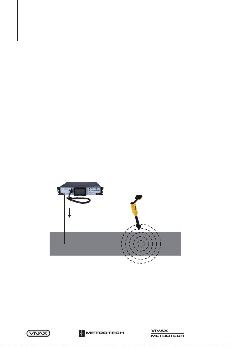
4.1 System Overview
The Vivax-Metrotech FLS-2 transmitter and vLoc series receivers locate underground
fiber optic cables. This user manual covers the FLS-2 transmitter. For instructions
about using the vLoc series receivers, see their instruction manuals.
The FLS-2 transmitter sends a predefined signal lower than 10 kHz along the metallic
sheath surrounding the fiber optic cable, generating an electromagnetic field for the
length of the cable.
The receiver is outside to locate the electromagnetic field around the underground
cable. When using one of the predefined transmitter signals, the receiver can estimate
the relative position and path of the cable.
Figure 4-1 FLS-2 Transmitter and Receiver
4.2 Transmitter Signals
The transmitter is a signal generator that consists of one or more programmed
frequencies that allow you to locate and trace the fiber optic cable. The predefined
frequencies are:
™
Page 8 of 49
4 Introduction
Signal Direction (SD): SD512 (256 Hz and 512 Hz)
Locate Signal (LS): LF512 (512 Hz)
Extremely Low Frequencies (ELF): • ELF10
• Other ELFs available upon request
Note: Other frequencies may be available upon request.
Table 4-1 Predefined Transmitter Frequencies
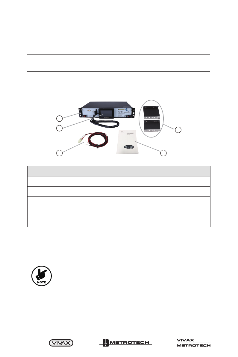
4.3 What’s in the Box
1
2
3
4
5
Figure 4-2 FLS-2 Transmitter – What’s in the box
No. Description
1 FLS-2 transmitter (with 19-inch brackets installed)
2 Hand-held Control Unit
3 AC or DC power cord, per order
4 Mounting bracket sets for 23-inch or 24-inch installation (with hardware)
5 Operating manual
4.4 Modular Design
The transmitter is a 2U chassis that contains removable front and rear modules. Figure
4-3 shows the locations of the front-accessible module and where to store the hand-
held display unit when not being used.
NOTE
See section 5.4, “Overview of the Modules for information about
the modules.”

™
Page 9 of 49
4 Introduction
1
2
345
6
Figure 4-3 FLS-2 Transmitter – Front and Side View
No. Description No. Description
1RS232 Connector (for factory
use) 4 Hand-Held display unit
2 USB port for software updates 5 Main control module
3 USB Host connector cover 6
LED
• Fail (Red)
• Status (Yellow)
• Power (Green)
Figure 4-4 shows the locations of the rear-accessible modules.
21
43 8 9 1110 10
65 7 21
43 8 9 11
65 7
Figure 4-4 FLS-2 Transmitter Rear View (AC-Left Figure., DC-Right Figure.)
No. Description No. Description
1
Power Module (AC or DC,
depending on the configured
system)
7 RJ-45 Network Connector
2 Power On/Off Switch 8 Signal Output Connector
3 Ground Stud 9 Relay interface for 2-way or 4-way
4 Power Input Connector
10 Telemetry Interface
5 Rear Module
6 Relay Interface for 16-ways 11 RJ-11 Phone Line Connector

™
Page 10 of 49
5 Overview
5. Overview
This chapter contains the following sections:
• Operating Modes
• Methods for Controlling the Transmitter
• Hand-Held Display Unit
• Overview of the Modules
• LED Status Indicators
5.1 Operating Modes
Table 5-1 list the transmitter’s operating modes. You can trigger the modes locally and
remotely.
NOTE
The term “local control” refers to the hand-held display unit in
this document. “Remote control” refers to using a touch-tone
telephone, mobile device or Ethernet.
Mode Description
Active Normal operation
Standby In Standby mode, the high-voltage circuit on the Power
Amplifier module and the output signal is off.
Table 5-1 FLS-2 Transmitter Operating Modes
5.2 Controlling the Transmitter
Figure 5-1 shows the various methods for controlling the transmitter. See Chapter 7,
“Local Transmitter Control,” and Chapter 8, “Remote Transmitter Control, for details.”
FLS
Transmitter Display
RJ11 (Modem)
Hand-held
Display Unit
Touch-tone
Telephone
RJ45 (Ethernet) PC or smart-phone
browser
Figure 5-1 Method of Controlling the Transmitter

™
Page 11 of 49
5 Overview
5.3 Hand-Held Display Unit
The hand-held display unit controls the transmitter through its touch screen. The
display unit’s coiled cord plugs into the “Display” RJ11 connector on the front of the
control module, as shown in Figures 5-2. When not in use, store the display unit on the
bar in front of the Main Control module.
NOTE
For information about using the attached hand-held display unit,
see section 7.1, “Using the Hand-Held Display Unit.”
5.4 Overview of the Modules
This section briefly describes the transmitter modules, including differences between
the AC and DC systems. For information about removing or installing the modules, see
section 11.2, “Removing or Installing Modules.”
5.4.1 Main Control Module
The transmitter has a main control module installed horizontally in the front of FLS-2. Two
screws and two ejector handles secure it, figure 5-2 shows the main control module.
This module mainly controls the transmitter. It contains the firmware, memory, and
modem circuit. The front connectors are for an optional computer and the hand-held
display unit. The modem circuit connects to the telephone line through the rear RJ11
connector.
Figure 5-2 Main Control Module
5.4.2 Power Supply Module
The FLS-2 provides the flexibility to choose either AC or DC power supply. It is located
at the back of the transmitter and secured by screws.
Figure 5-3 AC and DC Power Supply Module

™
Page 12 of 49
5 Overview
5.4.3 Rear Module
The FLS transmitter has the option of 2-way, 4-way, or 16-way transmissions. This
module has the RJ-11 phone line connector for the modem, an RJ-45 network
connector for local area network (LAN) connection, a connector for 2-way or 4-way
relays, and the connector for the 16-way relay interface.
This module also contains the high-voltage output connector and the telemetry
connector.
WARNING
Turn the rear power switch off before handling this module’s
connectors. The high-voltage output may be at 300V AC or 450V
DC.
Figure 5-4 Rear Module
5.5 LED Status Indicators
Table 5-2 Describes the module status indicated by the displayed LEDs. Before
removing any module, turn the rear power switch off.
LED LED Colors Description
Power
None The module is off.
Solid green The module is on.
Status
Solid yellow
An alarm was triggered.
NOTE: For detail, see Chapter 6, “Alarm
Messages.”
Blinking yellow Software is updating or flash programming, the
phone ringing.
Fail Solid red System failure – over current or temperature, etc.
Table 5-2 LED Status Indicator
The LED colors shown are after the system boot up, which takes approximately 30 to
60 seconds. There may be some flashing or changing LEDs during the system boot-up.

™
Page 13 of 49
6 Rack Installation of the Transmitter
6. Rack Installation of the Transmitter
This chapter contains the following sections:
• Installation Site
• Required Tools and Test Equipment
• Output Connector Pin-Out
• Attaching the Rack Mounting Brackets
• Installing or Replacing the Transmitter
• Testing the Transmitter.
• Telemetry Interface
NOTE
Read the General Safety instructions and this entire chapter
before installing the transmitter.
6.1 Installation Site
The installation site for the transmitter should meet the environmental and power
requirements for the transmitter. Follow the customer's specific company policies and
procedures.
6.2 Required Tools and Test Equipment
We recommend that the tools below be available during the transmitter installation.
Name Image
Crescent wrench, or 7/16 open-end
wrench or nut drive
Cutters
#2 Philips-head Screwdriver
Voltmeter
Table 6-1 Tool and Test Equipment

™
Page 14 of 49
6 Rack Installation of the Transmitter
6.3 Output Connector Pin-Out
Table 6-1 shows the high-voltage output jack's pin-out and mating connector.
Determine the conductor length needed to connect the transmitter output to the
external signal protection relay and ground control unit assemblies. Use a minimum of
18 AWG conductors rated minimum 600 V, minimum 80ºC, and the colors specified in
Figure 6-1.
NOTE
Discharge the above if the relay box is installed.
WARNING
Turn the rear power switch off before handling this module’s
connectors. The high-voltage output may be at 300V AC or 450V
DC.
Output Jack
Pin
1
2
3
Connection
Signal High
Signal Low
N.C.
Wire color
Blue
White
----
12 2
3 3
1
Mating Connector
Figure 6-1 Pin-Out for the Output Jack and Mating Connector
6.4 Attaching the Rock Mounting Brackets
The transmitter ships with three sizes of standard and adjustable mounting brackets,
allowing for installation in 19, 23, or 24-inch racks. The FLS-2 transmitter ships with
the 19-inch standard rack mounting brackets already attached. The adjustable rack
mounting bracket kit allows you to adjust the horizontal front-to-back position of the
transmitter up to 5.25-inches (133.4mm). Figure 6-2 shows the left bracket for the
adjustable brackets.
Measure the rack width and use the following instructions if you need to change the
bracket size.
To remove and install the rack mounting brackets:
1. Remove the attached mounting brackets using the Philips-head screwdriver and
save the flat-head screws.
2. Attach the new brackets to the same place with the flat-head screws.
This manual suits for next models
3
Table of contents
Other Vivax Metrotech Transmitter manuals


