Hycontrol VF05 Owner's manual

Issue 3
AH0123
1 / 41
VF05
VF05 2-WIRE GUIDED (TDR)
LEVEL TRANSMITTERS
USER AND PROGRAMMING MANUAL
(INCLUDES ATEX OPTION)
Hycontrol Ltd, Larchwood House, Orchard Street,
Redditch, Worcestershire, UK. B98 7DP
Tel: +44 (0)1527 406800 Fax: +44 (0) 1527 406810
Company registered in England No: 1755684

2 / 41
LEVEL MEASUREMENT TECHNICAL CONCEPTS

3 / 41
CONTENTS
1. INTRODUCTION ...........................................................................................................................................................4
2. ORDER CODES (NOT ALL COMBINATIONS POSSIBLE) ...................................................................................................4
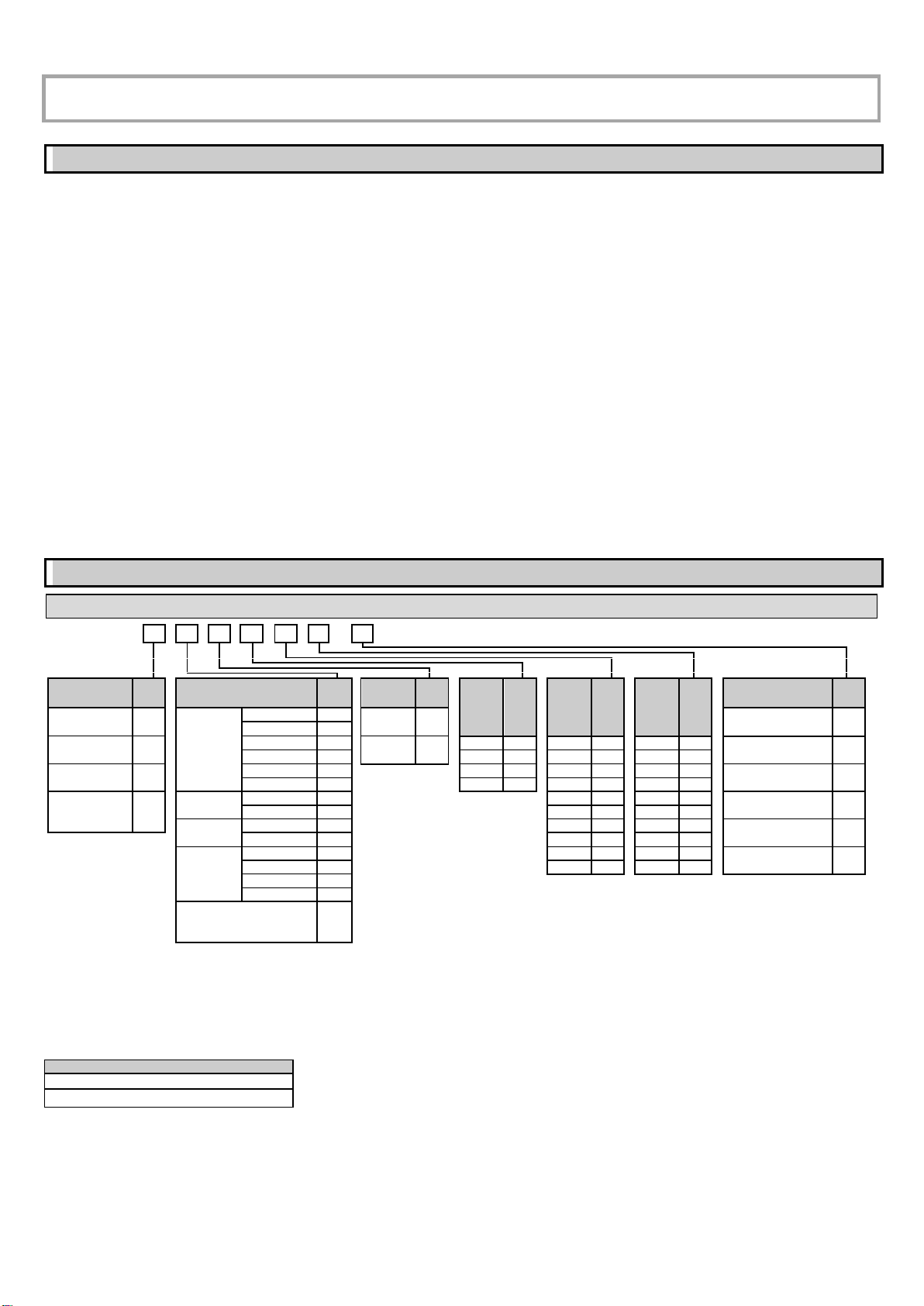
2.1. VF05 -WITH CABLE PROBE .....................................................................................................................................................4
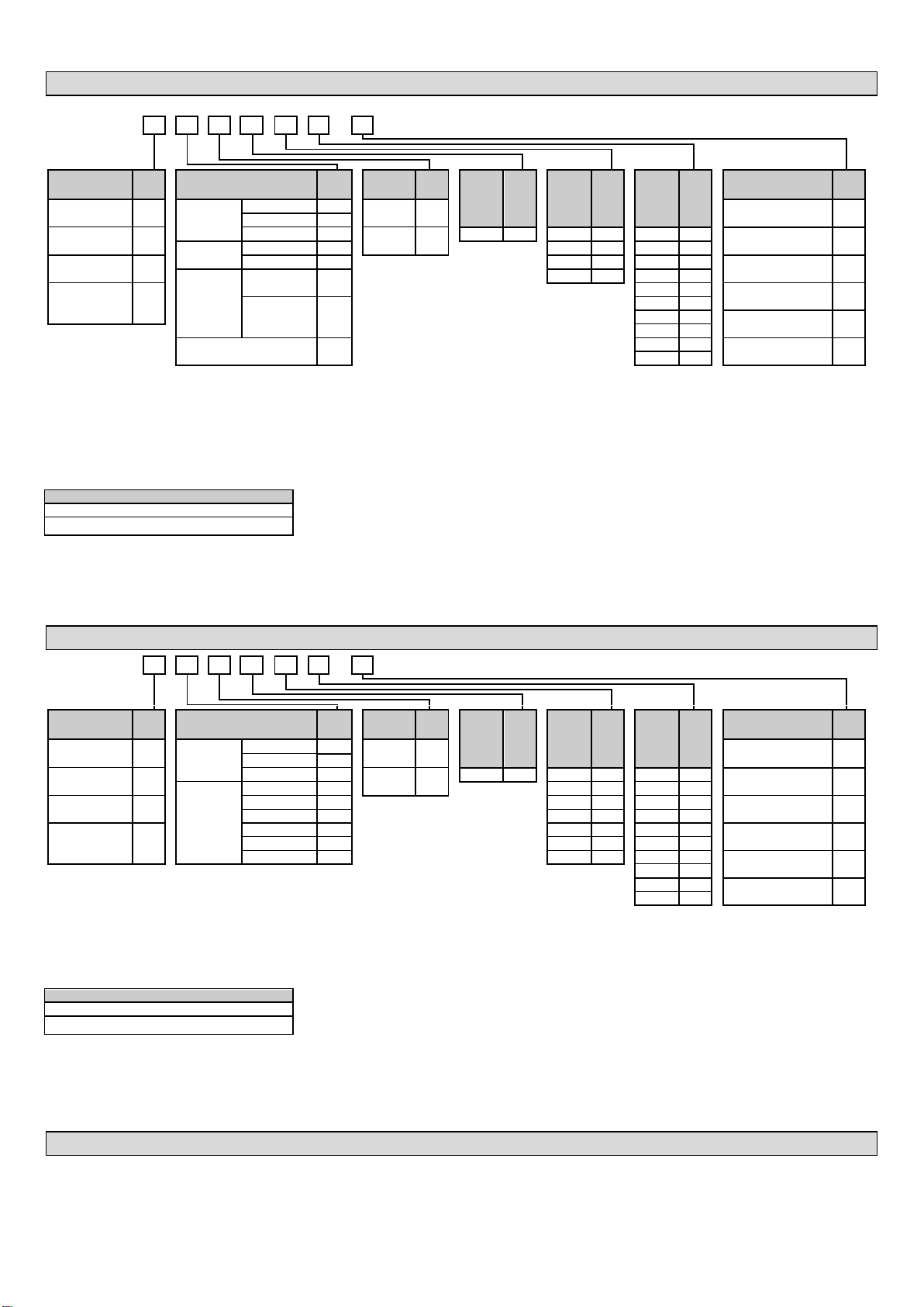
2.2. VF05 -WITH ROD PROBE .......................................................................................................................................................5
2.3. VF05 –WITH ROD PROBE OR COAXIAL ROD PROBE ......................................................................................................................5
2.4. ACCESSORIES........................................................................................................................................................................5
3. TECHNICAL DATA.........................................................................................................................................................6
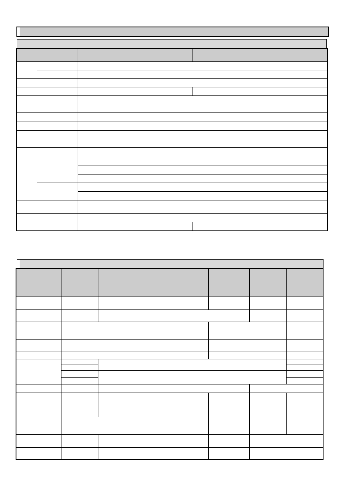
3.1. GENERAL.............................................................................................................................................................................6
3.2. PROBE PROPERTIES................................................................................................................................................................6
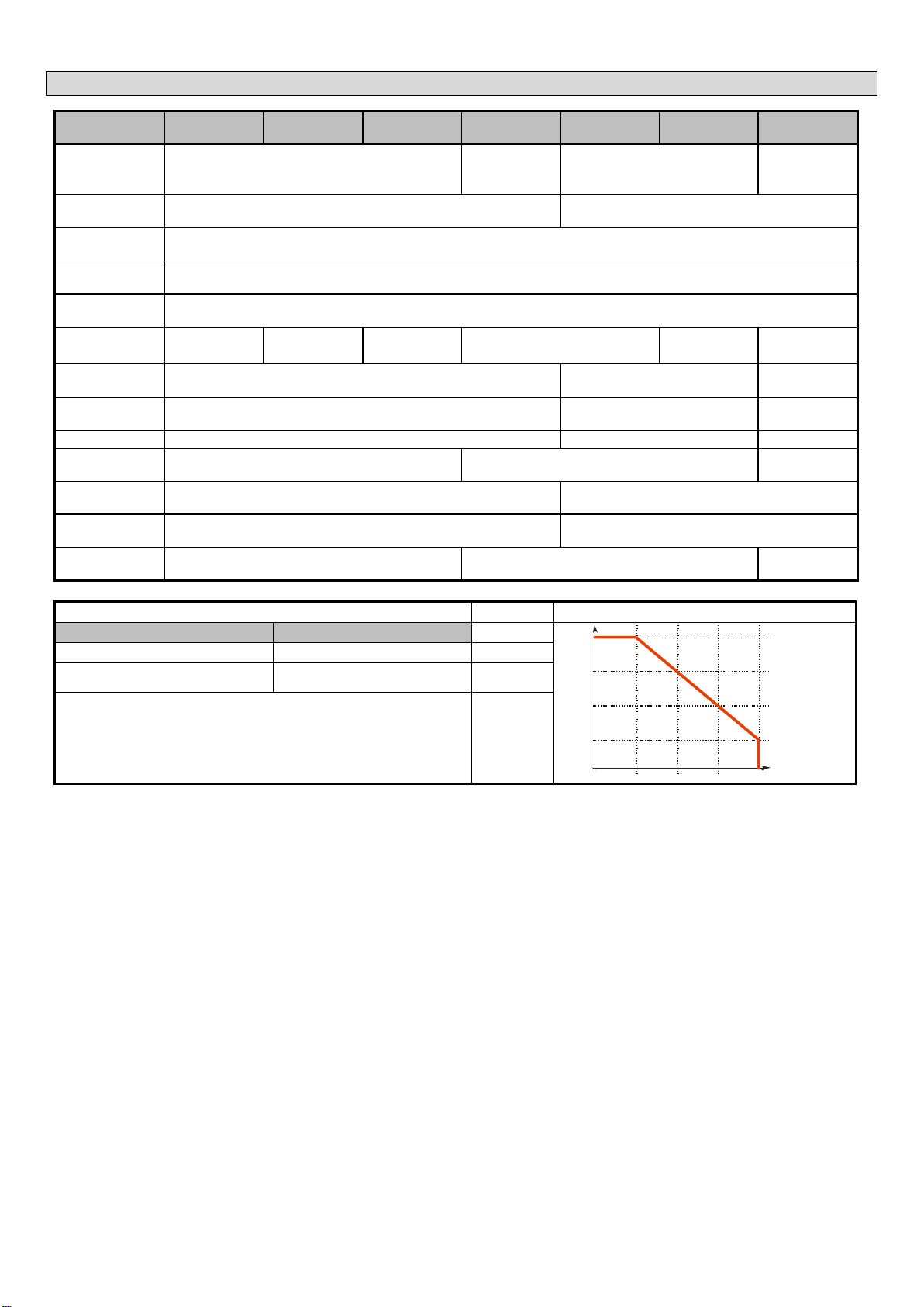
3.3. COATED PROBE PROPERTIES ....................................................................................................................................................7
3.4. DIMENSIONS........................................................................................................................................................................8
3.5. ATEX INFORMATION (FOR PRODUCTS CODES ENDING WITH EX).....................................................................................................9
3.5.1. ATEX General ............................................................................................................................................................9
3.5.2. ATEX nameplate........................................................................................................................................................9
3.5.3. ATEX Intrinsically safe protection (Ex ia)...................................................................................................................9
3.5.4. Temperature limit data for ATEX (Ex ia) approved models.....................................................................................10
3.5.5. ATEX explosive dust protection (Ex t)......................................................................................................................10
3.5.6. Temperature limit data for ATEX (Ex t) approved models ......................................................................................10
3.6. CONDITIONS FOR SAFE USE (INCLUDES ATEX)..........................................................................................................................11
3.7. MAINTENANCE AND REPAIR..................................................................................................................................................11
4. INSTALLING ...............................................................................................................................................................12
4.1. HANDLING AND STORAGE.....................................................................................................................................................12
4.2. MOUNTING ON CONTAINERS.................................................................................................................................................12
4.2.1. General mounting instructions ...............................................................................................................................12
4.2.2. Installing the Device for Measuring Solids ..............................................................................................................14
4.3. WIRING ............................................................................................................................................................................15
4.3.1. Design of the measuring network in non-explosive environments .........................................................................15
4.3.2. Connection in explosive environment .....................................................................................................................16
4.3.3. BUS (HART®) communication ..................................................................................................................................16
4.4. SWITCHING ON AND COMMISSIONING ....................................................................................................................................16
4.5. AVAILABLE USER INTERFACES ................................................................................................................................................16
5. PROGRAMMING........................................................................................................................................................17
5.1. PROGRAMMING WITH HYVIEW..............................................................................................................................................17
5.1.1. Installing and Running HyView ...............................................................................................................................17
5.1.2. Programming and Configuring the Device..............................................................................................................21
5.1.3. Programming Examples using HyView ...................................................................................................................32
5.2. PROGRAMMING WITH THE VGF-DISPLAY UNIT.......................................................................................................................33
5.2.1. VGF-DISPLAY Unit ...................................................................................................................................................33
5.2.2. The Behaviour of the VF05 while Programmed Manually ......................................................................................33
5.2.3. Manual Programming.............................................................................................................................................33
5.3. PROPERTIES OF VF05 TWO-WIRE MICROWAVE LEVEL TRANSMITTER ...........................................................................................35
5.3.1. Level Measurement –Level reflection, Threshold Line and Automatic Gain Adjustment.......................................35
5.3.2. To illustrate the five possible configurations, the following fluid level measurement settings are assumed .........36
5.3.3. Echo Loss Handling .................................................................................................................................................36
5.3.4. Typical Signal Forms ...............................................................................................................................................38
5.4. TROUBLESHOOTING.............................................................................................................................................................39

4 / 41
Thank you for choosing a HYCONTROL instrument.
We are sure that you will be satisfied throughout its use!
1. INTRODUCTION
Application
The VF05 two-wire guided microwave level transmitter measures the distance to the surface of liquids, solids and granules, from which the device calculates and
transmits the level, volume, or weight values as required.
The device can be used in storage and reaction tanks, rigid pipelines of suitable diameter and level reference vessels. The device can also be used with HART®
compliant HyView software or PACTware.
Operating Principle
The VF05 measurement method is based on TDR (Time Domain Reflectometry) analysis of the electromagnetic pulse travelling along the probe. The device sends
nanosecond-wide, low-power pulses along an electrically conductive rod, cable, or coaxial supply line at a known rate of light propagation speed. If the electromagnetic
pulse propagating along the conductor reaches a medium boundary with a different (r) dielectric constant (the surface of the measured medium or the phase boundary
of two liquids), some of the energy is reflected from there. The larger and sharper the (r) dielectric constant change at the boundary of the media, the better the
efficiency of the reflection (e.g., 80% of the energy is reflected from a flat air-water boundary).
The pulse is detected and processed by the device as a voltage signal. Since the propagation speed is known, the distance of the reflecting surface can be determined
by measuring the travel time of the pulse. The travel time is the time taken between sending the start of the pulse and the arrival of the reflected pulse which is
equivalent to twice the distance from the probe to the target. The device calculates the distance from the measured time and converts it into an electric signal
proportional to the distance, an output current of 4…20 mA, and provides a HARToutput signal and displays it on the optional display. Other derived quantities
(volume, weight, etc.) can also be obtained from the distance data using the device software. The advantage of the described measurement technology compared to
other level measurement methods is that dust, foam, steam or surface turbulence have no disturbing effect.
2. ORDER CODES (NOT ALL COMBINATIONS POSSIBLE)
2.1. VF05 -WITH CABLE PROBE
VF05
-
-
Ex*
2-wire guided microwave level transmitter
Version /
Temperature
Code
Probe / Process connection
Code
Housing
Code
Probe
length (4)
(x 10m)
Code
Probe
length (4)
(x 1m)
Code
Probe
length (4)
(x 0.1m)
Code
Output
Code
Transmitter (1)
T
Mono cable,
4 mm, 316
1" BSPP (G1)
K
Aluminium
7
4…20 mA + HART®
4
1" NPT
L
High-temperature
transmitter (2)
H
1½" BSPP (G1½)
V
Stainless
steel
9
0 m
0
0 m
0
0 m
0
4…20 mA + HART® /
Ex ta/tb IIIC (ATEX)
5
1½" NPT
W
10 m
1
1 m
1
0.1 m
1
Transmitter +
display(1)
B
1½" TriClamp
1
20 m
2
2 m
2
0.2 m
2
4…20 mA + HART® /
Ex ia IIIC (ATEX)
6
2" TriClamp
2
30 m
3
3 m
3
0.3 m
3
High-temperature
transmitter + display
(2)
P
Mono cable,
8 mm, 316
1½" BSPP (G1½)
N
4 m
4
0.4 m
4
4…20 mA + HART® /
Ex ia IIC/IIB (ATEX)
8
1½" NPT
J
5 m
5
0.5 m
5
Twin cable, 2x
4 mm, 316
1½" BSPP (G1½)
T
6 m
6
0.6 m
6
4…20 mA + HART® /
Ex ta IIIC (ATEX)
9
1½" NPT
U
7 m
7
0.7 m
7
Mono cable,
Ø4 mm, FEP-
coated (3)
1" BSPP (G1)
F
8 m
8
0.8 m
8
4…20 mA + HART®
+ Relay
H
1" NPT
G
9 m
9
0.9 m
9
TriClamp 1½"
X
Sanitary DN40
Y
Mono cable, Ø4 mm, + PFA/FEP
fully coated / DN50, PN25, 316Ti
+ PFA/FEP lining
M
* Ex versions are marked "Ex" right after the type designation on the label.
(1) Flange temperature max. +90 °C (+194 °F)
(2) Flange temp. max. +200 °C (+392 °F) (“M” type only up to +150 °C [+302 °F])
(3) Only the cable probe is coated
(4) Max. cable length is 30 m (100 ft)
Standard seal material is FPM (Viton) up to 200°C
Special seals (5)
EPDM up to 150°C
FFKM Perfluoroelastomer (Kalrez6375) up to 275°C
(5) The above special seals are ordered separately and must be specified in the text part of the order.
ATEX Note: - Devices with a display must NOT be operated in an “Ex ia IIC” environment
Devices with Plastic coated probes must NOT be operated in an “Ex ia IIC” environment
Refer to pages 10 & 11 for ATEX temperature limits

5 / 41
2.2. VF05 -WITH ROD PROBE
VF05
-
-
Ex*
2-wire guided microwave level transmitter
Version /
Temperature
Code
Probe / Process connection
Code
Housing
Code
Probe
length (4)
(x 10m)
Code
Probe
length (4)
(x 1m)
Code
Probe
length (4)
(x 0.1m)
Code
Output
Code
Transmitter (1)
T
Mono rod, ∅8
mm, 316Ti
1" BSPP (G1)
R
Aluminium
7
4…20 mA + HART®
4
1" NPT
P
High-temperature
transmitter (2)
H
1½" TriClamp
3
Stainless
steel
9
0 m
0
0 m
0
0 m
0
4…20 mA + HART® /
Ex ta/tb IIIC (ATEX)
5
Twin rod, 316Ti
1½" BSPP (G1½)
D
1 m
1
0.1 m
1
Transmitter +
display(1)
B
1½" NPT
E
2 m
2
0.2 m
2
4…20 mA + HART® /
Ex ia IIIC (ATEX)
6
Mono rod
PFA-coated
1½" TriClamp
PFA-coated
O
3 m
3
0.3 m
3
High-temperature
transmitter + display
(2)
P
0.4 m
4
4…20 mA + HART® /
Ex ia IIC/IIB (ATEX)
8
DN50, PN25,
316Ti flange,
PFA-coated
Q
0.5 m
5
0.6 m
6
4…20 mA + HART® /
Ex ta IIIC (ATEX)
9
0.7 m
7
Mono rod + PP-coated / DN50,
PN25, 316Ti + PP lining (3)
I
0.8 m
8
4…20 mA + HART®
+ Relay
H
0.9 m
9
* Ex versions are marked "Ex" right after the type designation on the label.
(1) Flange temperature max. +90 °C (+194 °F)
(2) Flange temp. max. +200 °C (+392 °F) (up to +150°C [+302 °F] with plastic-coated probes)
(3) High-temperature version not available
(4) Max. probe length is 3 m (10 ft)
Standard seal material is FPM (Viton) up to 200°C
Special seals (5)
EPDM up to 150°C
FFKM Perfluoroelastomer (Kalrez6375) up to 275°C
(5) The above special seals are ordered separately and must be specified in the text part of the order.
ATEX Note: - Devices with a display must NOT be operated in an “Ex ia IIC” environment
Devices with Plastic coated probes must NOT be operated in an “Ex ia IIC” environment
Refer to pages 10 & 11 for ATEX temperature limits
2.3. VF05 –WITH ROD PROBE OR COAXIAL ROD PROBE
VF05
-
-
Ex*
2-wire guided microwave level transmitter
Version /
Temperature
Code
Probe / Process connection
Code
Housing
Code
Probe
length (4)
(x 10m)
Code
Probe
length (4)
(x 1m)
Code
Probe
length (4)
(x 0.1m)
Code
Output
Code
Transmitter (1)
T
Mono rod (3),
14 mm,
316Ti
1½" BSPP (G1½)
S
Aluminium
7
4…20 mA + HART®
4
1½" NPT
Z
High-temperature
transmitter (2)
H
2" TriClamp
4
Stainless
steel
9
0 m
0
0 m
0
0 m
0
4…20 mA + HART® /
Ex ta/tb IIIC (ATEX)
5
Coaxial (3),
316Ti
1" BSPP (G1)
A
1 m
1
0.1 m
1
Transmitter +
display(1)
B
1" NPT
B
2 m
2
0.2 m
2
4…20 mA + HART® /
Ex ia IIIC (ATEX)
6
1½" BSPP (G1½)
C
3 m
3
0.3 m
3
High-temperature
transmitter + display
(2)
P
1½" NPT
H
4 m
4
0.4 m
4
4…20 mA + HART® /
Ex ia IIC/IIB (ATEX)
8
1½" TriClamp
5
5 m
5
0.5 m
5
2" TriClamp
6
6 m
6
0.6 m
6
4…20 mA + HART® /
Ex ta IIIC (ATEX)
9
0.7 m
7
0.8 m
8
4…20 mA + HART®
+ Relay
H
0.9 m
9
* Ex versions are marked "Ex" right after the type designation on the label.
(1) Flange temperature max. +90 °C (+194 °F)
(2) Flange temp. max. +200 °C (+392 °F)
(3) Can be ordered with segmented probe which must be specified in the text of the order. The length of the probe section is 1 m.
(4) Max. probe length is 6 m (20 ft)
Standard seal material is FPM (Viton) up to 200°C
Special seals (5)
EPDM up to 150°C
FFKM Perfluoroelastomer (Kalrez6375) up to 275°C
(5) The above special seals are ordered separately and must be specified in the text part of the order.
ATEX Note: - Devices with a display must NOT be operated in an “Ex ia IIC” environment
Devices with Plastic coated probes must NOT be operated in an “Ex ia IIC” environment
Refer to pages 10 & 11 for ATEX temperature limits
2.4. ACCESSORIES
•Hyview software –requires PC (Available as download) •2 x M20x1.5 cable gland
•User and Programming manual (Available as download) •VGF-DISPLAY unit (plug-in option)
•HARTUSB modem (sold separately).

6 / 41
3. TECHNICAL DATA
3.1. GENERAL
With aluminium housing
VF05–7–4, 5, 6, 8
With stainless steel housing
VF05–9–4, 5, 6, 8
Input
data
Measured values
Distance between the reference point and the plane of the reflection (surface of the material); derived values: level, volume or weight
Measuring range
Depends on the probe and the measured medium (refer to section 3.2 Probe properties or 3.3 Coated probe properties)
Probe types and technical data
Coaxial rod, dual cable, cable, dual rod, and rod probes (for technical data refer to the Technical Data of Probes table)
Housing
Cast aluminium with epoxy finish
Stainless steel
Process temperature
–30…+200 °C (–22…+392 °F) (for technical data refer to –MEDIUM TEMPERATURE table –Page 7)
Process pressure
–1…40 bar (–0.1…4 MPa [–14…580 psig]) (for technical data refer to –MEDIUM PRESSURE DIAGRAM –Page 7)
Ambient temperature
–30…+65 °C (–22…+149 °F), with display: –20…+65 °C (–4…+149 °F)
Seal
Standard temperature: FPM (Viton)Optional EPDM (150°C) or FFKM (275°C)
Ingress protection
IP67
Supply voltage
12(1)…36V DC, nominal 24V DC, Ex version: 12(1)…30V DC, transient overvoltage protection(2)
Output
data
Output signal
Analog: 4…20 mA; (3.9…20.5 mA) passive output; error signal 3.8 or 22 mA
BUS: serial, HARTinterface, termination resistor maximum 750 Ω
Display (optional): VGF-DISPLAY LCD dot-matrix
Relay (optional): SPDT 30V / 1A DC; 48V / 0.5A AC
Accuracy (2)
Liquids: 5 mm (0.2"). If probe length is ≥ 10 m (L ≥ 33 ft); 0.05% of probe length
Solids: 20 mm (0.8"). If probe length is ≥ 10 m (L ≥ 33 ft); 0.2% of probe length
Wiring
2× M20×1.5 cable glands, cable outer diameter: Ø6…Ø12 mm (Ø0.23…Ø0.47") (metal for Ex version, otherwise plastic) + 2× internally threaded ½" NPT
connection for protective pipes, wire cross-section: 0.5…1.5 mm2 (20 AWG…15 AWG) (shielded cable recommended)
Electrical protection
Class III
Weight (housing)
2.2kg (4.9 lbs)
3.9kg (8.6 lbs)
(1) Reliable operation in industrial environments can be guaranteed for terminal voltages > 13 V.
(2) The device has been tested and complies with EN IEC 61326-1: 2021 Table 2. I/O signal/control with (e) remark, Surge test.
(3) With ideal reflective surfaces and constant temperatures.
3.2. PROBE PROPERTIES
Type
VF05K––
VF05L––
VF05V––
VF05W––
VF05R––
VF05P––
VF05S––
VF05Z––
VF05N––
VF05J––
VF05T––
VF05U––
VF05D––
VF05E––
VF05A––
VF05B––
VF05C––
VF05H––
Version
4 mm cable
(0.15")
Rod
8 mm cable
(0.3")
4mm dual cable
(0.15")
Dual rod
Coaxial rod
Maximum measuring
range
30 m (100 ft)
3 m (10 ft)
6 m (20 ft)
30 m (100 ft)
3 m (10 ft)
6 m (20 ft)
Minimum measuring
range
r= 80 / 2.4
0.25 m / 0.35 m (0.82 ft / 1.15 ft)
0.15 m / 0.3 m (0.5 ft / 1 ft)
0 m (0 ft)
Min. distance to
objects
600 mm (Ø2 ft)
200 mm (Ø 0.65 ft)
0 mm (0 ft)
Minimum rof medium
2.1
1.8
1.4
Process connection
1" BSPP (G1)
1" BSPP (G1)
1½" BSPP (G1½)
1" BSPP (G1)
1" NPT
1" NPT
1½" BSPP (G1½)
1" NPT
1½" NPT
1½" BSPP (G1½)
1½" NPT
1½" NPT
Material of probe
316 (1.4401)
316Ti (1.4571)
316 (1.4401)
316Ti (1.4571)
Nominal diameter of
probe
4 mm (0.15")
8 mm (0.3")
14 mm (0.55")
8 mm (0.3")
4 mm (0.15")
8 mm (0.3")
28 mm (1.1")
Weight
0.12 kg/m
(0.08 lb/ft)
0.4 kg/m
(0.25 lb/ft)
1.2 kg/m
(0.8 lb/ft)
0.4 kg/m
(0.25 lb/ft)
0.24 kg/m
(0.16 lb/ft)
0.8 kg/m
(0.5 lb/ft)
1.3 kg/m
(0.85 lb/ft)
Separator material
–
PFA,
welded onto cable
PTFE-GF25
if length is
>1.5 m (5 ft)
PTFE,
if length is
>1.5 m (5 ft)
Tensioning weight
dimensions
Ø25 x 100 mm
(Ø1 x 4")
–
Ø40 x 260 mm
(Ø1.5 x 10")
Ø40 x 80 mm
(Ø1.5 x 3")
–
Material of tensioning
weight
316Ti (1.4571)
–
316Ti (1.4571)
316Ti (1.4571)
–

7 / 41
3.3. COATED PROBE PROPERTIES
Type
VF05F––
VF05G––
VF05X––
VF05Y––
VF05M––
VF05Q––
VF05O––
VF05I--
Version
∅4 mm (0.15") FEP-coated cable
∅4 mm (0.15")
fully FEP / PFA-
coated cable
Fully PFA-coated rod
Fully PP-coated
rod
Maximum
measuring range
30 m (100 ft)
3 m (10 ft)
Minimum measuring
range r = 80 / 2,4
0.25 m / 0.35 m (0.82 ft / 1.15ft)
Free space
requirement
600 mm (Ø2 ft)
Minimum rof
medium
2.1
Process connection
1” BSPP (G1)
/ 1” NPT
1½" Triclamp
DN 40 Sanitary
DN 50
1½" TriClamp
DN 50
Material of probe
316 (1.4401) / FEP
316Ti (1.4571) / PFA
316Ti (1.4571) /
PP
Nominal diameter of
probe
6 mm (0.23")
12 mm (0.5")
16 mm (0.62")
Mass
0.16 kg/m (0.1 lb/ft)
0.5 kg/m (0.33 lb/ft)
0.6 kg/m (0.4 lb/ft)
Coating of fillet and
tension weight
–
PFA
PP
Tensioning weight
dimensions
Ø25 x 100 mm (Ø1 x 4")
–
Material of
tensioning weight
316Ti (1.4571)
–
Maximum medium
temperature
+200 °C (+392 °F)
+150 °C (+302 °F)
+60 °C (+140 °F)
MEDIUM TEMPERATURE
MEDIUM PRESSURE DIAGRAM
Type
FLANGE TEMPERATURE
200°C
140°C
80°C
20°C
-30°C -1 bar 16 bar 24 bar 32 bar 40 bar
Base model
–30…+90 °C (–22…+194 °F)
High-temperature VF05Hor VF05P
transmitter
–30…+200 °C (–22…+392 °F)*
*Limited for coated probes, see Coated probe properties table above.
ATEX Note: The units with plastic coating cannot be used in group IIC class hazardous area.

8 / 41
3.4. DIMENSIONS
L = Probe (Insertion) length as specified in tables 2.1 –2.3.
VF05TK––
VF05TL––
VF05TV––
VF05TW––
VF05TR––
VF05TP––
VF05TS––
VF05TZ––
VF05TN––
VF05TJ––
VF05TT––
VF05TU––
VF05TD––
VF05TE––
VF05TA––
VF05TB––
VF05TC––
VF05TH––
VF05TF––
VF05TG––
VF05TX––
VF05TY––
VF05TM––
VF05TQ––
VF05TI––
Sanitary

9 / 41
3.5. ATEX INFORMATION (FOR PRODUCTS CODES ENDING WITH EX)
3.5.1. ATEX General
Instruments with the code VF05-7-5Ex, VF05-7-6Ex, VF05-7-8Ex, VF05-7-9Ex, VF05-9-5Ex, VF05-9-6Ex,
VF05-9-8Ex or VF05-9-9Ex are designated as ATEX instruments according to ATEX directive 2014/34/EU.See Ex markings and Maximum surface
temperature data for group, category and temperature classification data on pages 9 - 11.
3.5.2. ATEX nameplate
Example marking of approved instrument according to directive 2014/34/EU:
Example of a VF05 ATEX Ex ia nameplate Example of a VF05 ATEX Ex t nameplate
Guidance for installation, setup and repair
Installation, setup and maintenance must be in accordance with the applicable codes of practice and harmonised standards for Ex ia (intrinsic safe) equipment and
by qualified technical personnel only.
User repairs are not permitted; in case of faults return the unit to Hycontrol. See section 3.7 Maintenance and Repair for further information.
The level transmitter must be operated in an intrinsically safe circuit only.
The metal enclosure of the unit must be connected to the EP (Equipotential) circuit.
3.5.3. ATEX Intrinsically safe protection (Ex ia)
VARIANT WITH METAL HOUSING AND
VGF DISPLAY
VARIANT WITH METAL HOUSING
WITHOUT VGF DISPLAY
VARIANT WITH METAL HOUSING
NORMAL TEMPERATURE TYPES
VF05B--8 EX
VF05T--8 Ex
VF05B/T--6 EX
Ex marking (ATEX)
II 1G Ex ia IIB T6…T4 Ga
II 1G Ex ia IIC T6…T4 Ga
II 1D Ex ia IIIC T85°C…T110°C Da
HIGH-TEMPERATURE TYPES
VF05P--8 Ex
VF05H--8 EX
VF05H/P--6 EX
Ex marking (ATEX)
II 1G Ex ia IIB T6…T3 Ga
II 1G Ex ia IIC T6…T3 Ga
II 1D Ex ia IIIC T85°C…T180°C Da
Ex power supply data
Ui = 30 V, Ii = 140 mA, Pi = 1 W
Ci ≤25 nF, Li ≤300 H
Ui = 30 V, Ii = 100 mA, Pi = 0.75 W
Ci ≤25 nF, Li ≤300 H
Ui = 30 V, Ii = 140 mA, Pi = 1 W
Ci ≤25 nF, Li ≤300 H
Supply voltage range
12…30V DC
Electrical connection
Cable entry
M20x1.5 cable gland
Cable outer diameter
Ø6…12 mm
Wire cross section
0.5…1.5 mm2
Temperature limits
See tables in section 3.5.4.

10 / 41
3.5.4. Temperature limit data for ATEX (Ex ia) approved models
3.5.4.1 For standard temperature transmitters
Temperature data
Hazardous gas atmospheres
VF05T/B–7–8 Ex
VF05T/B–9–8 Ex
Explosive dust atmospheres
VF05T/B–7–6 Ex
VF05T/B–9–6 Ex
Ex ia IIC, Ex ia IIB
Ex ia IIIC
Maximum process temperature
+80 °C (+176 °F)
+90 °C (+194 °F)
+100 °C (+212 °F)
+80 °C (+176 °F)
+90 °C (+194 °F)
+100 °C (+212 °F)
Maximum surface temperature at
the process connection
+70 °C (+158 °F)
+90 °C (+194 °F)
+100 °C (+212 °F)
+75 °C (+167 °F)
+90 °C (+194 °F)
+100 °C (+212 °F)
Maximum ambient temperature
+65 °C (149 °F)
+65 °C (149 °F)
Temperature class
T6
T5
T4
T85°C
T100°C
T110°C
3.5.4.2 For high- temperature transmitters
Temperature data
Hazardous gas atmospheres
VF05H/P–7–8 Ex
VF05H/P–9–8 Ex
Explosive dust atmospheres
VF05H/P–7–6 Ex
VF05H/P–9–6 Ex
Ex ia IIC, Ex ia IIB
Ex ia IIIC
Maximum process
temperature
+80 °C
(+176 °F)
+90 °C
(+194 °F)
+100 °C
(+212 °F)
+180 °C
(356 °F)
+80 °C
(+176 °F)
+90 °C
(+194 °F)
+100 °C
(+212 °F)
+180 °C
(356 °F)
Maximum surface temperature
at the process connection
+70 °C
(+158 °F)
+90 °C
(+194 °F)
+100 °C
(+212 °F)
+175 °C
(347 °F)
+75 °C
(+167 °F)
+90 °C
(+194 °F)
+100 °C
(+212 °F)
+175 °C
(347 °F)
Maximum ambient temperature
+65 °C (149 °F)
+65 °C (149 °F)
Temperature class
T6
T5
T4
T3
T85°C
T100°C
T110°C
T180°C
3.5.5. ATEX explosive dust protection (Ex t)
Metal housing
High-temperature version with metal housing
VF05H/P–7–5 Ex
VF05H/P–9–5 Ex
VF05T/B–7–9 Ex
VF05T/B–9–9 Ex
VF05T/B–7–5 Ex
VF05T/B–9–5 Ex
Ex marking (ATEX)
II 1 D Ex ta IIIC T105°C Da
II 1/2 D Ex ta/tb IIIC T85°C…T110°C Da/Db
II 1/2 D Ex ta/tb IIIC T85°C…T180°C Da/Db
Waiting time for opening the
cover
0 min
30 min
30 min
Ex power supply*
Ui = 30 V DC Ii = 1 A
Supply voltage
12…30 V DC
Temperature limit data
See tables in section 3.5.6.
Cable entry
M20x1.5 cable glands with “Ex ta” protection
Cable outer diameter
Ø6…Ø12 mm (Ø0.23…Ø0.47")
Electrical connection
Wire cross-section: 0.5…1.5 mm2(20 AWG…15 AWG)
* Maximum supply voltage and current to the product while maintaining Ex protection.
3.5.6. Temperature limit data for ATEX (Ex t) approved models
3.5.6.1 For standard temperature transmitters
Temperature data
Explosive dust atmospheres
VF05T/B–7–9 Ex
VF05T/B–9–9 Ex
VF05T/B–7–5 Ex
VF05T/B–9–5 Ex
Ex ta IIIC
Ex ta/tb IIIC
Maximum process temperature
+65 °C (149 °F)
+80 °C (+176 °F)
+90 °C (+194 °F)
+100 °C (+212 °F)
Maximum surface temperature
at the process connection
+65 °C (149 °F)
+75 °C (+167 °F)
+90 °C (+194 °F)
+100 °C (+212 °F)
Maximum ambient temperature
+65 °C (149 °F)
+65 °C (149 °F)
Temperature class
T105°C
T85°C
T100°C
T110°C

11 / 41
3.5.6.2 For high-temperature transmitters
Temperature data
Explosive dust atmospheres
VF05H/P–7–5 Ex
VF05H/P–9–5 Ex
Ex ta/tb IIIC
Maximum process temperature
+80 °C (+176 °F)
+90 °C (+194 °F)
+100 °C (+212 °F)
+180 °C (356 °F)
Maximum surface temperature
at the process connection
+75 °C (+167 °F)
+90 °C (+194 °F)
+100 °C (+212 °F)
+175 °C (347 °F)
Maximum ambient temperature
+65 °C (149 °F)
Temperature class
T85°C
T100°C
T110°C
T180°C
3.6. CONDITIONS FOR SAFE USE (INCLUDES ATEX)
•Devices with an VGF-DISPLAY may NOT be operated in an “Ex ia IIC” environment.
•Intrinsically save devices may only be operated from a circuit that complies with the technical data of the device and is marked [Ex ia IIC] or [Ex ia IIB].
•Devices with a plastic-coated sensor may only be installed in an “Ex ia IIB” environment free of direct airflow causing charge transfer.
•The device may contain components capable of being electrostatically charged. The presence of electrostatic charges can cause sparks and ignition, so
electrostatic charges must be prevented entirely in potentially explosive (Ex) atmospheres.
oTo avoid static charge build-up on versions with a plastic-coated sensor, the following safety regulations must be observed:
oThe specific resistance of the medium to be measured shall be ≤ 104 Ωm.
oThe speed of the filling and emptying process must be chosen according to the medium.
oAvoid all mechanical contact with the plastic-coated probe.
oExtreme care must be taken during maintenance when there may be explosive residue in the process tank. The device may only be touched in
an explosive (Ex) environment with a wet antistatic cloth.
•Devices protected against dust ignition may only be operated in a circuit with the parameters specified in the technical data.
•With "Ex ta/tb IIIC" protection, the device cover may only be removed after a minimum waiting time of 30 minutes after de-energizing the device.
•Dust accumulation must be prevented on the housing of devices with "Ex ta/tb IIIC" protection.
•The aluminium content of the aluminium alloy housing exceeds the limit value, so the device must be protected against impact and friction in potentially
explosive (Ex) environments.
•If the device is installed in a place subject to overvoltage, the device must be equipped with overvoltage protection of at least overvoltage Class II
•The device must be earthed to the EP (Equipotential) system at the earthing screw point of the device.
3.7. MAINTENANCE AND REPAIR
For ATEX instruments refer to section 3.6 Conditions for Safe Use (Includes ATEX) as shown above.
User repairs are not permitted; in case of faults return the unit to Hycontrol.
VF05 does not require maintenance on a regular basis. In some very rare instances, however, the probe may need cleaning to remove deposited material.
This must be carried out gently, without damaging the probe.
Repairs during or after the warranty period are carried out exclusively at the Manufacturer. The equipment sent back for repair should be cleaned or disinfected by
the User prior to return. To arrange for return or repair fill in the online Return and Repairs form found at https://www.hycontrol.com/services/returns-and-repairs and
follow the instructions in the email acknowledgment or alternatively contact the service department.

12 / 41
4. INSTALLING
4.1. HANDLING AND STORAGE
Lift the instrument using both hands, or if necessary, use a hoist. Do not lift the instrument
by the probe. It is a critically sensitive part.
Protect the instrument from mechanical impacts and falling. The electronics
is a sensitive and fragile unit.
Do not bend coaxial or rod probes.
The device must be supported in the marked places.
The cable probe must not be looped, broken, or frayed.
The minimum bending diameter is 0.4 m (16″).
All these may cause a measurement error.
Storage temperature:
4.2. MOUNTING ON CONTAINERS
4.2.1. General mounting instructions
The size and position of fittings on the top of the tank (and the distance from the wall), the internal anti-reflection fittings, the rough joints, the welds and the shape and
design of the top and bottom of the tank are very important for the correct operation of the device. Any factor that affects the formation of the electromagnetic field of
the probe also significantly impairs the measurement accuracy. The coaxial probe is an exception because it has no external electromagnetic field.
Threaded process connection
Nozzle height
Nozzles penetrating into the tank
The easiest way to mount onto the tank is with a
device screwed into a 1" BSPP (G1), 1" NPT,
1½ " BSPP (G1½) or 1½" NPT threaded hole.
Do not use a nozzle longer than its diameter,
especially for single probes and powder applications.
h ≤ Ød, where
h = nozzle height
Ød = nozzle diameter
Consult HYCONTROL if the above condition cannot
be met.
The nozzle must not extend into the tank,
as the protruding part interferes with the
measurement.

13 / 41
Mounting two devices
Effects of material influx
Using a protective tube
If two devices have to be mounted
on one tank, they must be spaced at
least 2 m
(6.5 ft) apart to eliminate
interference and measurement
inaccuracies resulting from the
interaction of the two
electromagnetic fields.
Devices equipped with coaxial
probes are not subject to the above
warning because there is no
electromagnetic field outside the
probe's outer sheath.
Do not place the nozzle near the material inlet pipe
connector.
Material flowing onto the sensor probe causes incorrect
level indication. If there is not enough space, it is
recommended to install a baffle plate.
The floating lid is a common solution for petrochemicals. In
such cases, the use of a damping tube is recommended.
Straightness and contact of measuring probes
with other fittings and distance from the bottom of the tank.
Using a stirrer
After installation, the cable probes and the associated tensile
weight must be straight, tensioned, and away from other fittings
(e.g., mixer). They must not come into contact with the tank wall,
bottom, or other objects.
The installation space requirements of the different measuring
probes must be taken into account according to the data of the
measuring probes (see Technical Data).
There is no radiation cone along the probe.
When measuring liquids, the use of a reference chamber or damping tube is recommended,
since it provides mechanical and electromagnetic protection for accurate measurement.
Protect the device from direct sunlight
Attaching the probe to the bottom of the tank.
Flexible cable probes can be anchored to the bottom of the tank with a
fastener or loop.
Installing and shortening the cable probes
If necessary, the probe can be shortened.
Steps:
1. Loosen the grub screws (hexagon) with an Allen key.
2. Pull the cable out of the tension weight and cut to the desired size.
3. Insert the cable back into the weight as shown and tighten the screws.
4. Modify the configuration parameters to the new length, the reference
point being the upper edge of the weight.

14 / 41
4.2.2. Installing the Device for Measuring Solids
False readings
Coning and strong tensile force on the probe
The probe must not touch the side of the
nozzle.
Strong tensile force. The rope must not be
anchored when measuring solids.
The device is mounted at a distance of half the
radius of the tank from the top of the tank with a
minimum lift nozzle height.
It prevents excessive mechanical stress when
emptying the tank.
The tensile force of the probe cable depends on the height and shape of
the tank, the fragmentation of the material, the density, and the speed of
discharge.
The following table gives the tensile load values for the different materials
(approximate data in tons).
Probe type
Material
Probe length
6 m
(20 ft)
12 m
(40 ft)
24 m
(80 ft)
Single cable, Ø8 mm (Ø0.31″), max. load: 3.0 T
Cement
0.6 T
1.2 T
2.4 T
Ash
0.3 T
0.6 T
1.2 T
The measured process material can accumulate on the probe and nozzle, which reduces the energy of the measuring pulse.
Avoid creating cavities within the material.
Observe the load capacity of the tank top, which must support the maximum tensile force of the probe.

15 / 41
4.3. WIRING
Wiring in non-explosive environments
1. Take the device’s lid off.
2. Put the cable through the cable gland to the terminal block.
3. Remove the outer insulation for ~80 mm (~3.15″) from the cable so the wires can be accessed, then strip the
wires for 4 mm. Strip the shielding from the signal cable.
4. Connect the cable to terminal 2 and 3 (polarity is irrelevant).
5. Retract the cable so the cable’s outer insulation runs through the cable gland for about 10 mm (0.4″). Then
tighten the cable gland’s nuts with two wrenches.
6. Organize the wires in the compartment.
7. Put the lid back on.
Do not perform high voltage insulation test on the device due to the internal electronic surge protection.
Connecting (grounding) to equipotential network (EP)
Electrostatic discharge (E.S.D.)
Threaded earth connection (EP) on the side of the housing,
maximum wire cross-section: 4 mm² (12 AWG). The housing of
the device must be earthed to ground with a resistance of
R1 Ω.
The shield of the test lead if connected must be earthed at the
instrument panel. Do not run the test lead near high-current
cables, as shielding does not provide protection against
switching harmonics.
The device is protected against 4 kV ESD.
Warning: Electrostatic discharge in the measuring system
cannot be solved by only the device’s internal ESD
protection. It is the user's responsibility to ensure that the
tank, measured material and probe are grounded.
Risk of injury.
The probe may accumulate an electrostatic charge during
regular operation, so discharge it to the ground by touching
it (tank side) when installing.
Ground the inlet and the measured medium.
4.3.1. Design of the measuring network in non-explosive environments
Power supply
Nominal voltage
24 V DC
Maximum voltage (Uin):
36 V DC
Minimal voltage (Uin):
Depends on the impedance. (See diagram)
Loop resistance, Rloop
RHART + Rcable + Rammeter
Minimum RHART
0 Ω
Maximum RHART
750 Ω
RHART resistance for HART®communication
250 Ω (recommended)
Line A: minimum voltage on the device’s input terminals
Line B: minimum supply voltage (voltage drop on the device and the 250 Ω loop
resistance)
An example for calculating the supply voltage:
The minimum supply voltage at Imin = 4 mA current:
Usupply min.= Uin min.+ (Imin * loop resistance) = 12 V + (4 mA * 0.25 kΩ) = 13 V
The minimum supply voltage at Imax = 22 mA current:
Usupply min.= Uin min.+ (Imin * loop resistance) = 11.5 V + (22 mA * 0.25 kΩ) = 17 V
Therefore, if the loop resistance is 250 Ω, 17 V is just enough for the entire 4…20 mA
measuring range.

16 / 41
4.3.2. Connection in explosive environment
The intrinsically safe certified VF05 device may only be used in conjunction with other intrinsically safe certified equipment.
All the allowed electrical safety data indicated on the nameplate must be observed.
An ’Ex’ repeater power supply unit must be used.
For calculation of the supply voltage the same applies as for the
standard non-’Ex’ version.
The connected Ex repeater must be HART®-compatible so that
it can be operated with the HyView communication software.
The HART adapter, if connected, must be connected to the safe
area input of the intrinsically safe Ex repeater.
The units with plastic coating can only be used in an Ex ia IIB
environment free of direct airflow causing charge transfer.
4.3.3. BUS (HART®) communication
The output of the device can be used in two ways: 1. Current loop output and HART®2. Passive, HART®protocol
The HyView program supports the use of both modes.
According to the HART®communication standard it can be used as a point-to-point connection between a VF05 as a “slave” and a HART®“master”.
There are two modes of communication:
•If the device (HART®short address 0) is set to current loop transmission (4…20 mA), only one device can be in the HART®communication loop.
•For multidrop operation (4mA), several devices (max. 15) can be connected to one HART®communication loop. In this case, a short address other than 0
must be set for each device with each address unique.
4.4. SWITCHING ON AND COMMISSIONING
Measuring starts less than 20 seconds after switching on. Attention! The initial current consumption of the device is 3.5 mA right after switching on. If there is
a change in the installation data due to shortening a cable probe, the set parameters must be changed according to the application before starting the measurement.
4.5. AVAILABLE USER INTERFACES
The instrument can be programmed by using the following devices / accessories:
VGF-DISPLAY unit
See ”5.2. Programming with the VGF-DISPLAY unit.”
HyView software (PC needed)
Available as download
HART®Microlink USB modem
Ordered separately. See ”5.1. Programming with HyView”

17 / 41
5. PROGRAMMING
There are two ways to program the VF05.
−Programming with the HyView software
−Programming with the VGF-DISPLAY unit
5.1. PROGRAMMING WITH HYVIEW
5.1.1. Installing and Running HyView
The “HyView HART Configuration Software” (hereafter HyView) does not require installation, however prior to running the application, we recommend installing the
FTDI Driver (Virtual COM-PORT), available to download from the website of FTDI (http://www.ftdichip.com/Drivers/VCP.htm).
Electrical connections: Connect the transmitter to a PC using a HARTUSB modem (sold separately).
All the necessary parameters and function settings can be performed with HyView.
5.1.1.1 Running HyView
Run the HyView.exe application.
The above splash screen will appear.
5.1.1.2 Adding a Network
Click “Network” from the menu then click the Add Network button.
Choose the communication port.
Click the Ok button.

18 / 41
5.1.1.3 Detecting a device
Click the Detect button to start the device selection on the selected communication port.
The above Scanning network window appears when the detection starts
A device has been detected.

19 / 41
To select the detected devices tick the checkbox and click Detect settings button.
Parameter reading is in progress.
Device has been detected and settings are being read.

20 / 41
Settings have been read.
Other manuals for VF05
1
Table of contents
Other Hycontrol Transmitter manuals
Popular Transmitter manuals by other brands

Harris
Harris ATLAS ANALOGUE manual

Garrett
Garrett WT-1 user guide

VPG
VPG BLH NOBEL PS1010T Operator's manual

Clas Ohlson
Clas Ohlson F-164A instruction manual

HumanTechnik
HumanTechnik Lisa RF infrared motion transmitter operating instructions

HK Instruments
HK Instruments AVT Series installation instructions

FISCHER
FISCHER MS13 operating manual

M-system
M-system 10VF instruction manual

La Crosse Technology
La Crosse Technology TX38U-IT quick start guide

SpreadNet
SpreadNet SN935-DT installation instructions

Carson
Carson Reflex Wheel Pro 2 Telemetry 500500038 instruction manual

Williams Sound
Williams Sound WIR TX75/b user guide