Gigo TERRAIN WALKERS 7427 User manual

# 7427
EXPERIMENTS
134
PIECES
6+
AGES
8
MODELS
134
PIECES
6+
AGES
8
MODELS

Table of Contents ...........................1
Safety Information .........................2
Kit Contents
.....................................3
Tips for Assembly ..........................4
Overview .........................................5
Check It Out: Legged Robots .......7
Check It Out: Intro to Gears ..........8
1. Terrain Walker .............................9
Check It Out: Gear Ratios ............15
2. RoBoar ......................................16
3. RoboMouse ...............................21
Check It Out: Special Gears........ 24
4. Leopard Crawler........................25
5. Water Bear Robot..................... 28
6. Fairy Shrimp Bot...................... 33
7. Kangaroo Bot.............................37
8. Monkey Bot................................41
Check It Out: Linkages................ 45
TABLE OF CONTENTS
Learn more about the special,
noncircular gears that make these
models walk on page 24.
On pages 5–6 you can see all the
models at a glance.
1

SAFETY INFORMATION
Warning! Not suitable for children under 3
years. Choking hazard — small parts may
be swallowed or inhaled. Strangulation
hazard — long string may become
wrapped around the neck.
Keep the packaging and the instructions as
they contain important information.
Store the experiment materials and
assembled models out of the reach of
small children.
The models are intended for indoor use.
Do not use your models in a sandbox or in
water.
The electronic components of this product are recyclable. For the sake of the
environment, do not throw them into the household trash at the end of their
lifespan.
They must be delivered to a collection location for electronic waste, as
indicated by the following symbol:
Please contact your local authorities for the appropriate disposal location.
Notes on Disposal of Electrical and Electronic Components
Before starting the experiments,
read through the instruction manual
together with your child and discuss
the safety information. Check to make
sure the models have been assembled
correctly, and assist your child with the
experiments.
We hope you and your child have a lot
of fun with the experiments!
Dear Parents and Adults,
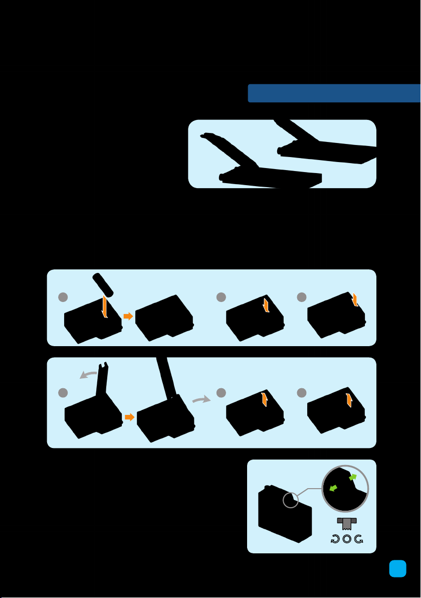
››› Three AA batteries (1.5-volt, type LR6)
are required for operation.
››› The supply terminals are not to be
short-circuited. A short circuit can cause
the wires to overheat and the batteries
to explode.
››› Dierent types of batteries (e.g.,
rechargeable and standard) or new and
used batteries are not to be mixed.
››› Do not mix old and new batteries.
››› Do not mix alkaline, standard (carbon-
zinc), or rechargeable (nickel-cadmium)
batteries.
››› Batteries are to be inserted with the
correct polarity. Press them gently into
the battery compartment. See page 4.
››› Always close the battery compartment
with the lid.
››› Non-rechargeable batteries are not to be
recharged. They could explode!
››› Rechargeable batteries are only to be
charged under adult supervision.
››› Rechargeable batteries are to be removed
from the toy before being charged.
››› Exhausted batteries are to be removed
from the toy.
››› Dispose of used batteries in accordance
with environmental provisions, not in the
household trash.
››› Be sure not to bring batteries into contact
with coins, keys, or other metal objects.
››› Avoid deforming the batteries.
››› Please remove the batteries if the toy is
likely to be unused for a long time.
Safety Advice for Batteries
2

What’s inside your experiment kit:
Checklist: Find – Inspect – Check o
No. Description Qty. Item No.
1B-SHORT PEG 30 7344-W10-C2D
2C-20mm AXLE CONNECTOR 20 7413-W10-T1P2
3C-30mm AXLE CONNECTOR 8 7413-W10-U1S
4C-1 HOLE CONNECTOR 6 7430-W10-B1D
5C-OD8x30mm TUBE 2 7400-W10-G1D
6C-MOTOR AXLE 2 7026-W10-L1S1
7C-30mm AXLE II 4 7413-W10-N1D
8C-NONCIRCULAR GEAR 6 7427-W10-E1P
9B-4-SIDED PYRAMID PIECE 2 7128-W10-E4G
10 C-BENDED ROD 5 7061-W10-V1P
11 C-3 HOLE ROD 2 7026-W10-Q2D
12 C-3 HOLE ROD FRONT CLOSED 3 7026-W10-X1D
13 C-5 HOLE ROD FRONT CLOSED 3 7413-W10-R1S3
14 C-2 HOLE ROUND ROD FOR AXLE 4 7427-W10-A1S
15 C-5 HOLE ARCH ROD 8 7427-W10-D1S
No. Description Qty. Item No.
16 C-6 HOLE ARCH ROD 8 7427-W10-D2S
17 C-5 HOLE PROLATE ROD 1 7443-W10-C1S
18 C-5X5 FRAME 1 7413-W10-Q1S2
19 C-HEXAGONAL BODY PLATE 1 2 7427-W10-F2P
20 C-HEXAGONAL BODY PLATE 2 6 7427-W10-F1P
21 C-10HOLE60°ARCH ELBOW,LEFT 2 7427-W10-B1S
22 C-10HOLE60°ARCH ELBOW,RIGHT 2 7427-W10-B2S
23 C-7 HOLE 120°ARCH ELBOW,LEFT 2 7427-W10-C1S
24 C-7 HOLE 120°ARCH ELBOW,RIGHT 2 7427-W10-C2S
25 C-100X MOTOR WITH SWITCH 1 7427-W85-A
26 C-700mm STRING 1 R39-W85-70
27 B-PEG REMOVER 1 7061-W10-B1Y
KIT CONTENTS
You will also need: 3 X AA batteries
(1.5 Volt, type LR6)
3
1 2 3 4 5
10 11 12
6789
13 14 15 16 17
18 19 20 21 22
23 24
25
26 27

TIPS FOR ASSEMBLY
Insert
Remove
4
PEG REMOVER
Side A of the peg remover can be
used to easily remove pegs.
Side B can be used to loosen firmly
inserted parts, such as axle.
BATTERIES How to insert and remove the batteries
Insert: Insert three new AA batteries. Make sure you fit the positive and negative ends into
the compartment in the direction indicated (with the correct polarity).
Remove: When it is time to replace the batteries, remove the old batteries by prying the
first battery gently out of the compartment with the peg remover. Then, it is easier to re-
move the other batteries with your fingers.
100X MOTOR WITH SWITCH
How to use
Inside the 100X motor with switch, there is an electric
motor, a gear train, and batteries. The batteries power
the electric motor, which turns the gears and the axle
shaft. Axles on your models are connected to the axle
shaft. The motor can be run in two directions. A three-
way switch allows you to choose between clockwise,
off, and counterclockwise motion. After playing with
your model, please turn off the switch. When storing,
remove the batteries and store in a clean, dry place.
ON
ON
ON ONOFF

OVERVIEW
5
RoBoar
Terrain Walker
Water Bear Robot
Fairy Shrimp Bot
Build these
functional models
one at a time!

OVERVIEW
6
Leopard Crawler
RoboMouse
Kangaroo Bot
Monkey Bot

CHECK IT OUT
7
These old wind-up
toy robots walked
on two legs.
This diagram shows a Klann linkage, a
type of multi-leg walking mechanism.
Learn about linkages on page 45.
This four-legged
robot is called the
SpotMini and is
made by a company
called Boston
Dynamics.
Boston
Dynamics also
designed Atlas,
this two-legged,
or bipedal, robot
that mimics the
way a human
walks. This
robot can walk,
run, jump, and
even pick things
up and carry
them in its arms.
LEGGED ROBOTS
Legged robots are robots that
walk on mechanical limbs. While
many robots roll around on wheels
— which are mechanically very
ecient — legged robots have the
ability to walk over obstacles and
surfaces that wheeled robots cannot
move over. Legged robots can go
places that wheeled robots cannot.
Designing a robot to walk on legs is
more complicated than designing
one that rolls on wheels. The ability
for various animals, humans includ-
ed, to walk on legs is actually quite
a feat of nature. Robot engineers
often look to nature for inspiration
when it comes to designing legged
robots.
Legged robots must keep their
balance while shifting from one leg
to another. They use sensors like
gyroscopes and accelerometers
to tell their motors how to move in
order to stay balanced. It takes a lot
of power to move a robot’s legs, and
when that power comes from heavy
battery packs inside the robot’s
body, it can pose quite a challenge.
As batteries get lighter, and sensor
systems get more advanced, it is
becoming increasingly popular for
robots to mimic human and animal
walking motion.
Legged robots can have any num-
ber of legs. The more legs, the more
stable the robot is. But robots with
fewer legs are more maneuverable.

CHECK IT OUT
8
The
Antikythera
mechanism
››› Build the first models and
look for gears in them.
GEAR WHEELS AND GEAR
TRAINS
If you look at the complicated machines
that exist today, it’s hard to imagine
that gears and gear trains have been
around for such a long time. In fact,
they have been in use for thousands of
years. One impressive example is the
mysterious “Antikythera mechanism,”
built over 2,000 years ago in Greece. It
is a geared machine that was used to
perform automatic calculations of the
position of the sun and the moon. Even
back then, gears were hard at work.
Gears are simply wheels with teeth on
them that mesh with the teeth on other
gears. There is no point to having just
one gear all by itself. But as soon as you
have two of them, you have a system
that transmits force and rotating motion.
This kind of transmission system is
called a gear train.
Of course, there are also transmission
systems without gears. Pulley blocks,
used for lifting loads, are a good ex-
ample. They are made of pulleys and
a rope. But most transmission systems
work with gears. Sometimes, chains
interlock with the gears as well. If you
have a bicycle with a derailleur system
for shifting gears, you have seen this
before.
Some gear trains use gears that aren’t
round. In a rack and pinion, a round
gear called the pinion engages with
the teeth on a linear bar called the
rack. In this way,
rotating motion
is converted into
linear motion.
Gears also come
in spiral, oval, and
ring shapes. And
the gears in this
kit have a very
unique shape
that enables the
walking motion of
the models.

Terrain Walker 1
Model
Make sure there are batteries in
the 100X motor with switch first.
Important! Check both sides and make sure the parts are oriented exactly as shown:
9
3 4
12
Inner side Outer side
1 2
1. The gears must
mesh together.
Turn one of the
gears all the way
around and make
sure all of the gears
turn smoothly.
2. The middle tooth
of the middle gear
must be pointing
straight up.

Terrain Walker
1
Model
10
5
7
6
1. The gears must
mesh together.
Turn one of the
gears all the way
around and make
sure all of the gears
turn smoothly.
2. The middle tooth
of the middle gear
must be pointing
straight down.
Important! Check both sides and make sure the parts are oriented exactly as shown:
12
Inner side Outer side

Terrain Walker 1
Model
Important! Check both sides again.
The middle tooth of the middle gear is
pointing straight up.
The 2 hole round rods for axle are
aligned with the green arrows as shown.
11
9
8
The middle tooth of the middle gear is
pointing straight down.
The 2 hole round rods for axle are
aligned with the green arrows as shown.
side view
side view

Terrain Walker
1
Model
12
11
1312
14
10
side view

Terrain Walker 1
Model
13
15
17
19
16
18
side view

Terrain Walker
1
Model
Switch the motor to turn clockwise
for forward motion.
14
20
››› Use the string to make a leash for
your model and take it for a walk!
21
23
22
Done!
• The model walks best on a smooth tabletop or hard
floor, but if the surface is too smooth, it might slip.
Test different surfaces and see what works! The
model will not walk on carpet except very low-pile
carpet.
• Pick up the model by the middle body plates.
• The model works best if you give it a little forward
momentum when letting it go on the tabletop.
ON

CHECK IT OUT
15
››› Read the next Check It Out section to learn
about the unique gears in this kit.
40 teeth
Driver gear 10 teeth
Driven gear
Number teeth driven gear
Velocity
ratio
=
Number teeth driver gear
(1:4)
10
40
1
4
= =
UNDERSTANDING GEAR RATIOS
DIRECTION OF MOTION
When two gear wheels are placed next to each
other, their teeth mesh together. When one of
the gears turns, the other gear will turn as well,
automatically moving along with the rst gear.
Interlocking gear wheels transmit a rotational
movement.
When you pay close attention to the directions
that two interlocking gears are turning, you
will see that one gear turns in one direction
(for example, clockwise) and the other gear
turns in the other direction (for example,
counterclockwise). So gears can be used to
reverse the direction of rotation.
SPEED AND TORQUE
When gear wheels have dierent diameters
and, as a result, a dierent number of teeth,
their rotational speeds will also be dierent.
The larger wheel turns slower than the smaller
one.
This shows that gear wheels can be used to
convert a slow rotational movement into a
faster rotational movement and vice versa. For
example, if the larger gear wheel has 40 teeth
and the smaller wheel has ten, the smaller
wheel will complete four rotations in the time it
takes the larger wheel to do one rotation. This
relationship between the input speed and the
output speed is known as the gear ratio. In this
case, the ratio is 1:4.
If you were to use your hand to slow down the
second gear while you turned the rst gear, you
would notice that you needed to apply force to
do it. Interlocking gears also transmit force.
The force of rotary motion is called torque.
Speed and torque have an inverse relationship
in a gear train. This means that if the driven
gear is turning slower than the driver gear,
the driven gear can exert more torque at
its circumference than the driver gear.
The fact that gear trains don’t just transmit
rotational speeds — that they also transmit
force — has signicant advantages in
machines. Bicycles use gears to make
pedaling easier. If you want to cycle over
at terrain or downhill, you can switch
into a large gear at the pedal and a small
gear at the rear wheel. This optimizes for
speed at the rear wheel, but also requires
more torque at the pedal. But when you’re
cycling uphill, you can switch to a small
gear at the pedal and a large gear at
the rear wheel. This allows you to apply a
smaller force on the pedals and turn them
at a faster rate, converting that force into a
larger torque, but slower speed, at the
rear wheel.
Gear trains can be found inside many
machines and devices. For example, in
mechanical clocks, the kind you might
see in a museum, gear wheels enable the
movement of a gear wheel propelled by a
spring or weights to be transmitted to the
hands of the clock. Thanks to the dierent
gear ratios, the hands can move quickly
(the second hand), slowly (the minute
hand), or even slower (the hour hand).

RoBoar
2
Model
16
12
12
1
5
3
2
4
Important! Make sure the parts are oriented exactly as shown:
Inner side
Inner side
Outer side
Outer side
1. The gears must mesh
together.
Turn one of the gears all
the way around and make
sure all of the gears turn
smoothly.
2. The middle tooth of
the middle gear must be
pointing straight down.
1. The gears must mesh
together.
Turn one of the gears all
the way around and make
sure all of the gears turn
smoothly.
2. The middle tooth of
the middle gear must be
pointing straight up.

RoBoar 2
Model
17
7
6
8
Important! Check both sides again.
The middle tooth of the middle gear is
pointing straight down.
The 2 hole round rods for axle are
aligned with the green arrows as shown.
The middle tooth of the middle gear is
pointing straight up.
The 2 hole round rods for axle are
aligned with the green arrows as shown.
Make sure there are batteries in
the 100X motor with switch first.

RoBoar
2
Model
18
11
13
9
12
10

RoBoar 2
Model
19
15
17
16
14
Table of contents
Other Gigo Toy manuals