Gigo Water Power 7323 User manual

What’s on
technology
15
165
pieces
#7323
models
to build
WATER
power

WATER power | Contents
Parts List ................................................................................................................. 1
Learning about Gears............................................................................................ 2-4
Learning about Chain Gears ................................................................................... 5
Tips and Tricks for Model Building .......................................................................... 6
About the Main Components of HYDRO-PNEUMATIC .......................................... 7
Notes for Assembly ..................................................................................................8
Notes for Operation ..................................................................................................9
Hydro-Pneumo ...................................................................................................... 10
Hydro-Pneumo Models (with water-recycling system)
How to Operate .................................................................................................. 11
Model 1 Cutting Machine ............................................................................. 12-13
Model 2 Grinder............................................................................................ 14-15
Model 3 Truck ............................................................................................... 16-17
Model 4 Excavator ........................................................................................18-19
Model 5 Detective ........................................................................................ 20-21
Model 6 Tank ................................................................................................ 22-23
Model 7 Antique Car .....................................................................................24-25
Hydro-Pneumo Models (without water-recycling system)
Water-Jet Vehicles ............................................................................................. 26
Experiment ......................................................................................................... 27
Model 8 Rocket Car ..................................................................................... 28-29
Model 9 Excavator .......................................................................................30-31
Model 10 Heavy Motorbike ...........................................................................32-33
Model 11 Helicopter ..................................................................................... 34-35
Model 12 Detective Car ................................................................................ 36-37
Model 13 Lift.................................................................................................. 38-39
Model 14 Antique Car .................................................................................. 40-42
Model 15 Propeller Aircraft ......................................................................... 43-45
RECOMMENDATIONS
Please read these instructions, follow the safety rules and keep them for reference. We
recommend that you make the models in the order that is given. You will then be able to
understand assembly of parts and soon many more different models you wish.
WARNING TO PARENTS
• This is a toy that has been designed for children over 8 years of age. It is not suit-
able for children under 3 years of age. It contains small parts that a child could
swallow. It must be kept out of the reach of very young children.
• Discuss the safety warnings and possible risks involved with the children before
allowing them to build these models.

1
Parts List | WATER power
PCS
1
1
2
3
1
1
1
1
1
80
2
1
1
1
3
1
1
80
1
No
1
2
3
4
5
6
7
8
9
10
11
12
13
PARTS NAMES
SECURED AIR-WATER STORAGE
RECYCLED WATER STORAGE
RACING TIRE
SHORT FRAME
SECURED PUMP
AIR-WATER POWER PACK
STORAGE CAP
NOZZLE
WASHER
UNIT CHAIN
90 DEGREE CONVERTER - L
S DR. AXLE
ROD
No
14
15
16
17
18
19
20
21
22
23
24
25
26
PARTS NAMES
LONG FRAME
L DR. AXLE
XL DR. AXLE
SECURED ONE-WAY SWITCH
BENDED ROD
90 DEGREE CONVERTER - R
L SECURITY NUT
GEAR FIXING
5-HOLE ROD
DUAL ROD
S SECURITY NUT
PEG
O RING L
PCS
5
2
2
1
4
2
2
4
2
2
2
20
2
TOTAL 165
No
27
28
29
30
31
32
33
34
35
36
37
38
39
PARTS NAMES
L PULLEY
SQUARE FRAME
S CHAIN GEAR
S GEAR
M CHAIN GEAR
DOUBLE-SIDED BASE GRID
LONG ROD
PEG /AXLE REMOVER
TUBE - B 120CM
M GEAR
CAR LAUNCHER
L CHAIN GEAR
TUBE - A 200CM
PCS
2
1
2
2
2
1
1
1
1
2
1
2
1
1
2
4
5
6
7
8
9
10
11
12
15
2319
24 25
26
27
28
32
33
36
37
38 39
31
34 35
20 21
22
29
16
17
18
13
14
30
3
x 1
x 1x 1
x 1
x 1
x 1
x 1
x 1
x 1 x 1
x 1
x 1
x 1
x 1
x 1
x 1
x 5
x 2
x 2x 2
x 2
x 2
x 2x 2
x 2
x 2
x 2
x 2
x 2
x 3
x 4
x 4
x 80
x 20 x 2
x 2
x 2
x 1
x 2

2
WATER power | Learning about Gears
Every transmission system (gear train) contains gears. A gear is a useful and important transmission compo-
nent, as it is a transmission method that applies to two shafts, or between a wheel and a shaft.
You can observe the transmission of meshing gears inside old toys or old clocks. There is a gearbox within the
transmission system of cars, which combines meshing gears of different sizes. In this way, to change among
different speeds becomes easy.
Do you know how gears work? Please carefully read the descriptions below. You will learn the secrets of gear
trains from the world patent GIGO GEARS. The design of GIGO scientic educational building blocks ( that is
GIGO SCIENCE-TOOL KIT ) is based on the number of 10 and its multiples; whether on the size of the com-
ponents, the distance between the holes, or the unique GIGO gear tooth number. Therefore your child will be
able to not only correctly assemble the gears, but also conveniently calculate the gear ratio or change the rotary
speed. Different from other gear designs adopting the number of 8 or 7 as their fundamental number, GIGO
gears are created with perfect designs for the use of scientic teaching, and express the care on children and
passion for scientic education.
We suggest a gradual learning with GIGO gears which starts from the basic structures to understand the combi-
nations of each component. Once you nish your practice following the examples in this instruction, and possess
the fundamental concepts of gear trains, you can put your unlimited creativity into action and create various
vehicles or airplanes on your own. Let’s enjoy the pleasure of creativity!
The wheel which has many tooth-shaped objects sticking out of the rim with the same size is called a “gear”. Two
gears can mesh with each other with the teeth on the rims. When a gear rotates, the other one will be driven to
rotate as well. The intermeshing teeth of the two gears transmit rotation and torque.
A simple gear train uses two gears with the
same or different sizes. If one of these gears is
attached to a motor or a crank, it takes the role
as the driver gear. The gear that is turned by
the driver gear is called the driven gear. Gears
are used to increase or decrease the speed or
the power of rotary motion. The mechanism of
changing the speed or power is called the gear
ratio (speed ratio).
Fig. B
Illustration of gear ratio calculation
Fig. A
The intermeshing of gears
can effectively transmit ro-
tation. The red circle rep-
resents the actual diam-
eters of the transmission,
which is called the pitch
diameter. The tting shape
of the teeth assures the in-
termeshing and transmits
power along the pitch.
GEAR
40 teeth
driven gear
20 teeth
driver gear
(2:1)
Velocity
ratio =
= =
Number teeth driven gear
Number teeth driver gear
40
20 1
2

3
160 T
20 T 40 T
60 T 80 T
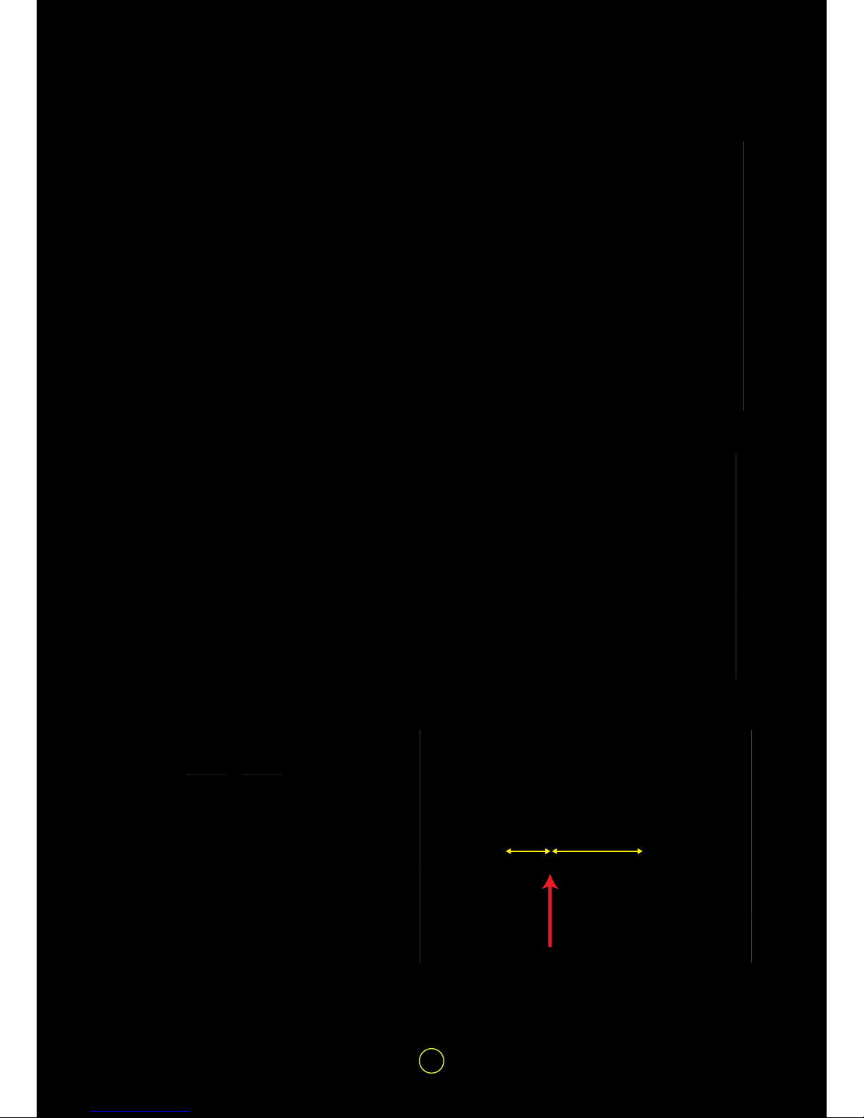
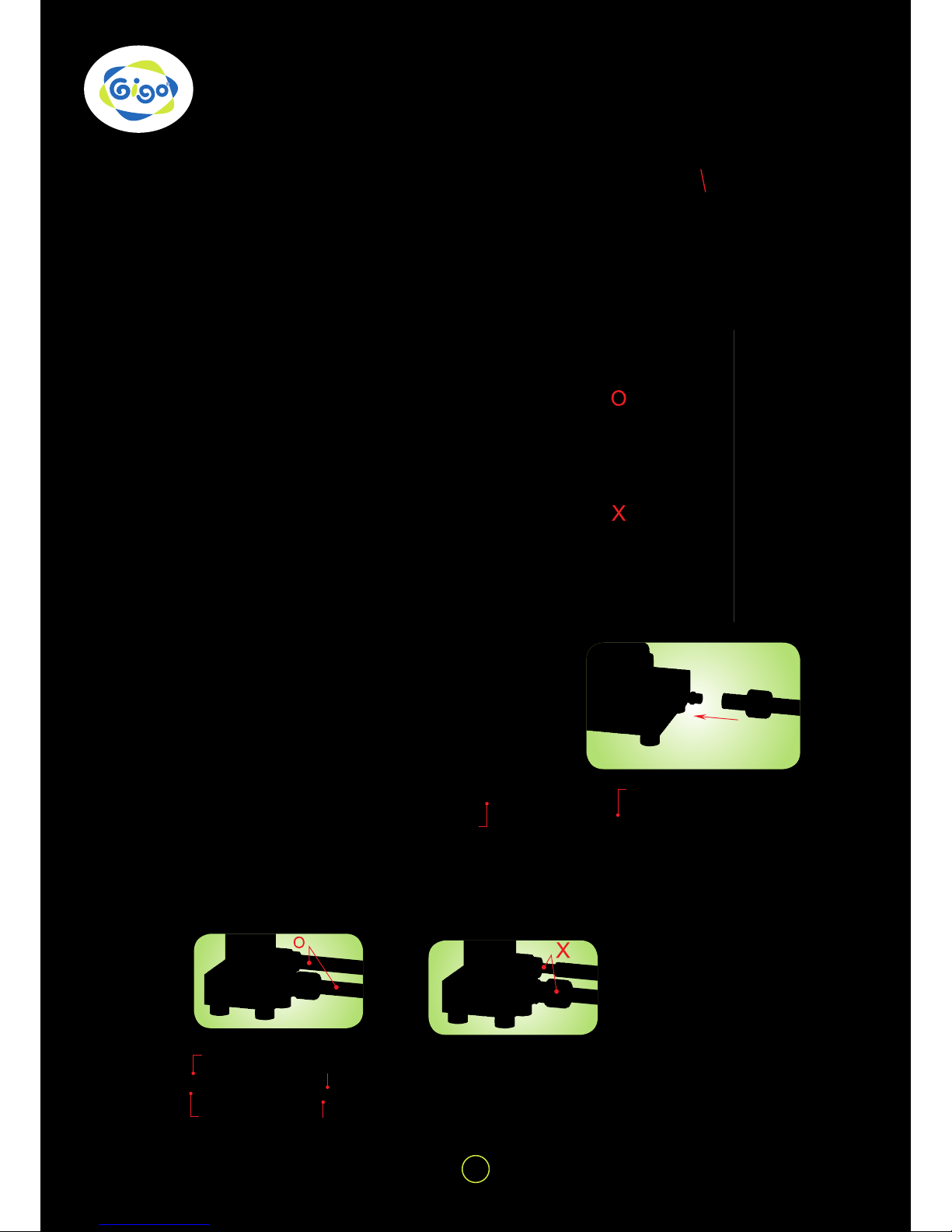
The secret of GIGO designs for gears is
to place the distance between each hole
based on 10 or the multiples. In Fig. E, the
distance between the centers of the two
gears is
and therefore the two gears can be
smoothly assembled or transmitted. Oth-
er sizes of GIGO gears are also designed
with the same perfect concept, and their
holes and gears can be greatly meshed
and operated with each other!
Learning about Gears | WATER power
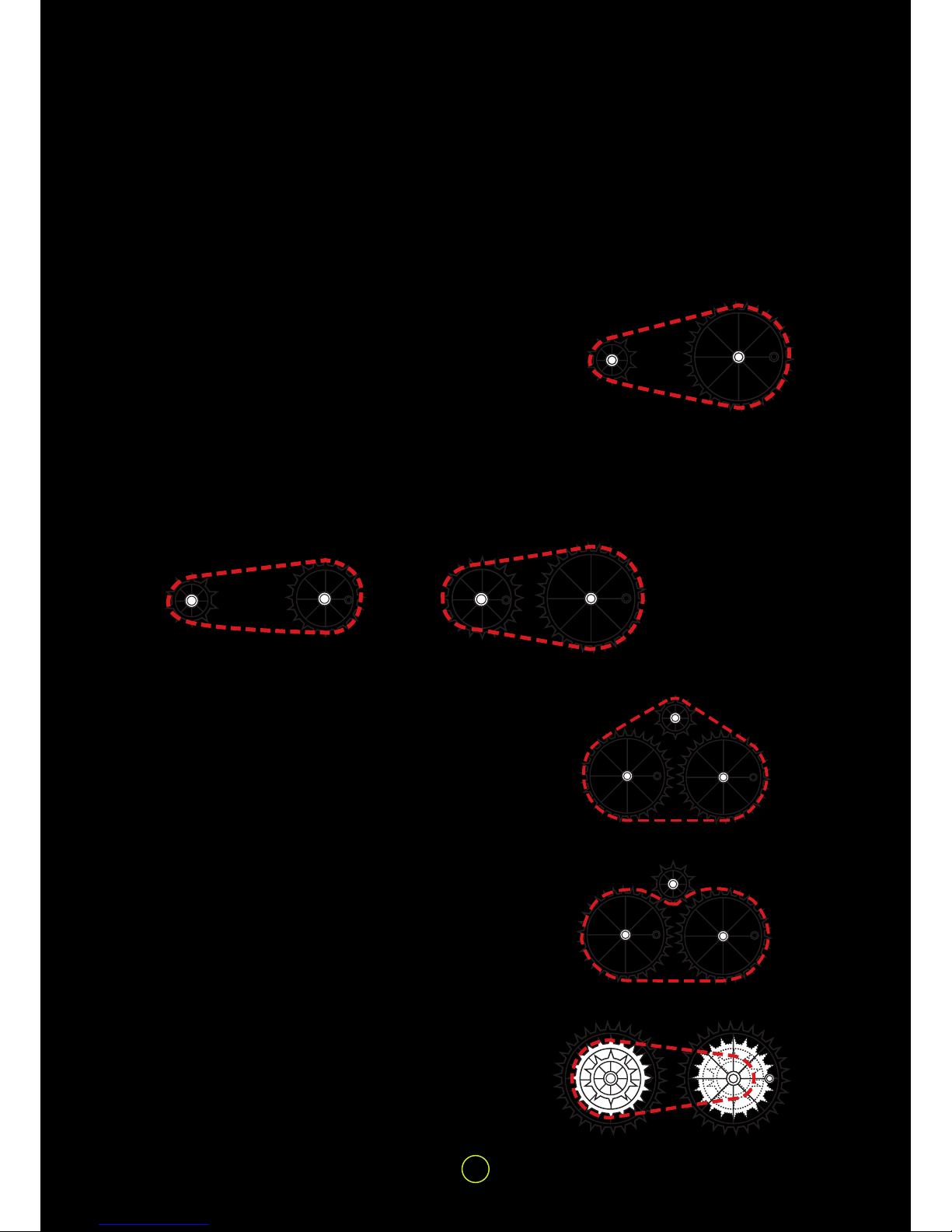
The number of teeth between the big gear
and small gear is different. Despite the
teeth number or size of the gears, the teeth
of the gears in the same gear set should
have the same size. In simple gear trains,
the driver and driven gears will rotate in
opposite directions. When a third gear
is inserted between the driver gear and
driven gear, and makes them rotate in the
same direction, it is called an idler gear.
The world patent gears designed by GIGO
come in 5 different types: 20T, 40T, 60T,
80T, and 160T, the extra large gears.
Each of GIGO gear sets contains both
spur and bevel gears. Gears of HYDRO-
PNEUMATIC contain “Spur Gears” (gear
wheel to gear wheel) meshing in the same
plane and regulating speed or direction of
turning of the shafts and “Bevel Gears”
(the rounded off sections on one edge of
your gears in the set) meshed together
to change direction at right angles to the
initial turning plane of the gears and shafts
(axles).
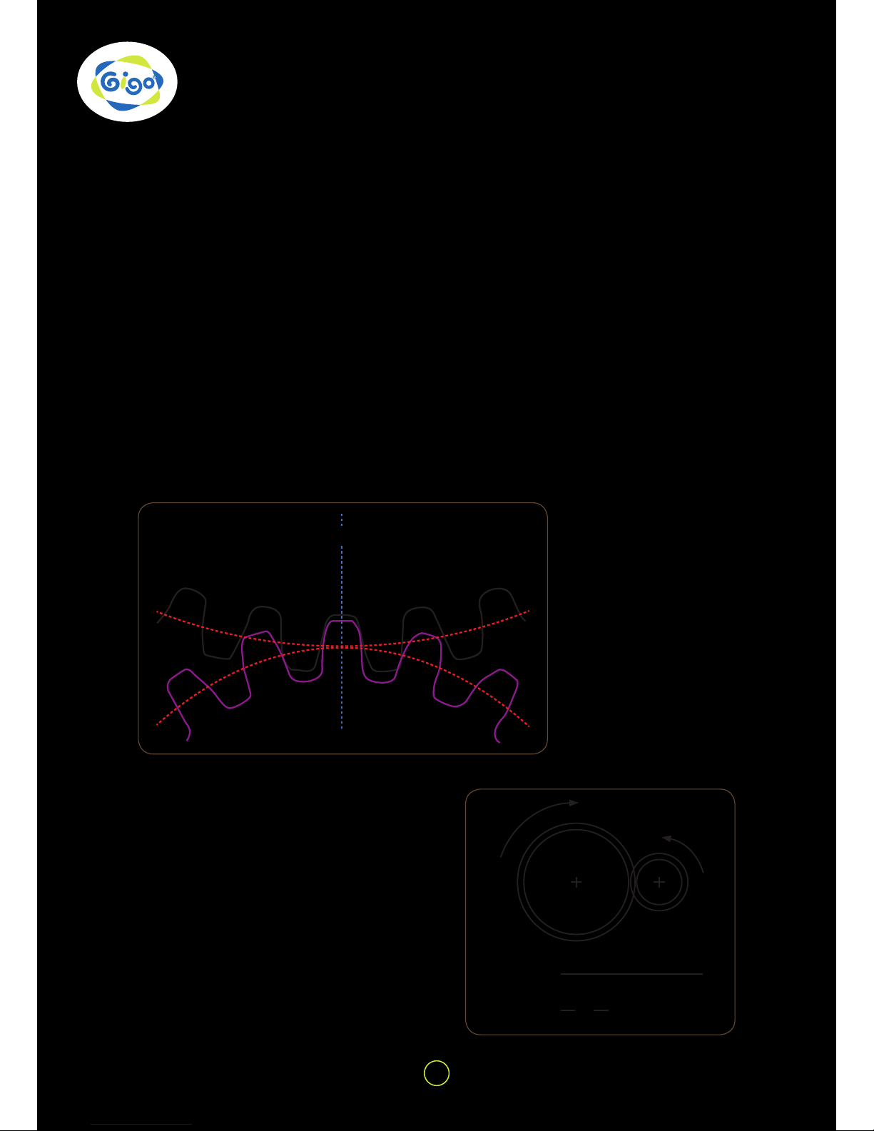
The tooth shape of GIGO gears shares the
same speci cation of module pitches=1.
Namely, the pitch diameter of the 20T
gears is 20mm while the pitch diameter of
the 40T gears is 40mm. The pitch diame-
ters refer to the imaginary circles between
the meshed gear teeth as shown in Figure
E.
Fig. D Characteristics of GIGO gear teeth
Fig. E The transmission between the pitches
during the intermesh of two gears
Fig. C GIGO Gears
= 30mmR1+R2 = +
20mm
240mm
2
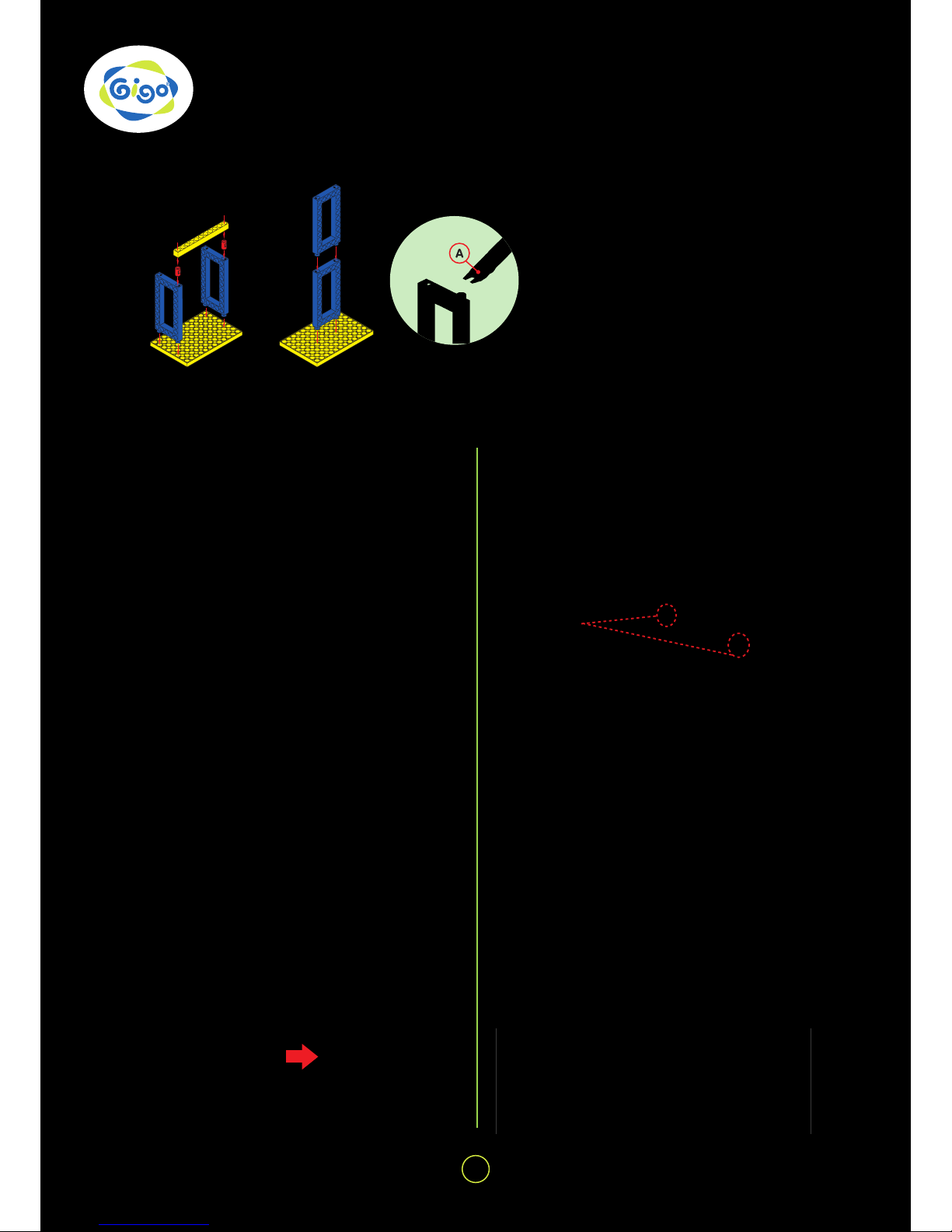
* According to the instruction above, can
you gure out how many holes there are
between a 40T and a 60T gear when they
are meshed?
R1 R2

4
WATER power | Learning about Gears
1. Use two red 20-tooth gears and two yellow
60-tooth gears to make this system.
2. How many times do you have to turn the small
gear A in order to make the second large gear D
turn once?
The small gear A turning the large gear B gives a 3
to 1 ratio as you found out on the table.
The second small gear C is directly driven by the
arrangement and produces another 3 to 1 ratio
with the second large gear D.
Did you nd out that you had to turn the small gear
A 9 times to turn the second large gear D once?
The overall gear ratio of the system is 9 to 1. ( A
gear ratio of 3 to 1 multiplied by another 3 to 1 =
9 to 1).
3. Add a third red 20-tooth gear to the short drive
axle at (x). Why does it lock?
4. Add a blue 40-tooth and a red 20-tooth gear to the
system. Can you work out mathematically what the
gear ratio of system would be?
Count the number of turns. Were you right?
1. This gear box uses a combination of red 20-tooth
gears and yellow 60-tooth gears.
There are four pairs of red 20 and yellow 60-tooth
gears. Each pair produces a gear ratio of 3 to 1.
The overall gear ratio would then be 3 x 3 x 3 x 3
= 81.
If gear B is turned 81 times then gear A would turn
once.
2. If gear A could be turned once then gear B would
turn 81 times! Could you add another pair of gears
to make a ratio of 243 to 1?
A
C
D
BX
D
B
A
C
40
20
A
B

5
Learning about Chain Gears | WATER power
1. The power transmission of chain gears depends on chains in-
stead of meshing each other. The teeth of chain gears must go
with chains. The “working” diameters of the chain gears are
about 10mm (10-tooth), 20mm (20-tooth) and 30mm (30-tooth).
Try to ensure that when connecting drive chains they are nei-
ther too tight nor too loose so that the motion of one is transmit-
ted efciently to the other. If the lengths can not exactly t the
distance a little looser will work better than a little tighter, only
that the drive chains come off the chain gears. This system can
be found in normal bikes or escalators.
2. Connect a 10-tooth chain gear to a 30-tooth chain gear as
shown.
3. Use a pencil point, or something similar, to turn B.
Which way does A turn?
Would this be the same if A and B were two gears in mesh?
How many times would you have to turn A for B to rotate once?
The gear ratio of these two chain gears would be _ to _ ?
4. Repeat the experiment for the two other arrangements and
make a table of your results for all three.
5. Try chaining a 10-tooth chain gear and two 30- tooth chain
gears together. Turn A clockwise.
What happens to B and C?
Do they turn in the same direction? Do they turn at the same
speed?
6. Try to chain the 10-tooth chain gear C as shown.
Turn A clockwise. What happens to B and C?
Do they turn in the same direction?
Do they turn at the same speed?
7. By connecting two sets of chain gears together three speeds
can be obtained.
This system is widely used in transmission bikes by adding a
gear shift in between.
A B
A B
A B
A B
C
A B
C

6
WATER power | Tips and Tricks for model building
FIXING BASE GRID, RODS AND FRAMES
FIXING GEARS
1. The peg can be used to join rods and
frames (Fig. 1).
2. Frames can be connected directly to
each other end to end (Fig. 2).
3. Using the end “A” of the peg/axle re-
mover to pull a peg off as Fig. 3 shows.
When xing gears onto the frame with a drive axle,
be sure to keep a proper space (about 1mm) be-
tween the gears and the frames. Try to turn the gear
and con rm if every gear in the gear train can turn
smoothly so that the least friction will be created and
then the most ef cient power transmission can be
expected (Fig. 4 & 5).
When you use a power pack to drive a wheeled ve-
hicle, the gear wheels should be arranged in sym-
metry (the holes on the two opposite chain gear
wheels must be kept in a horizontal line) and be
kept at the same driven speed, or the motor will stall
and the vehicle won’t move (Fig. 8).
Fixing gears to the frame Arranging gear wheels in symmetry
NG! (without a space)
TIP! These
two holes
must be kept
in a horizontal
line.
Gear fi xing
Gear xings are designed
to prevent a pulley or gear
from moving along the
axle, or slipping. They are
easy to be installed with-
out removing any wheel or
axle (Fig. 6).
Meshing gears at 90°
When the two red gears
mesh with each other at 90°
the one on the drive axle
must be assembled as close
as possible to the outer end
of the axle so that the mesh
can be ensured (Fig. 9).
Use a chain gear to connect two drive axles to
lengthen when necessary (Fig. 7).
Lengthening drive axles Connecting unit chains
Ensure to get the face of each unit chain when con-
necting them to one another as a drive chain so
that the transmission can be done ef ciently and
smoothly (Fig. 10).
Fig. 1
Fig. 4 Fig. 5
Fig. 6
Fig. 7
Fig. 9
Fig. 10
Fig. 8
Fig. 2 Fig. 3
OK! (with a space)

7
About the main components of Hydro-Pneumatic | WATER power
Air-Water Power Pack
“A” is the entrance and “B” is the exit. Air
and water enter the power pack through the
entrance to strike the water wheel directly
and drive the mechanism behind it. Then
the water ows back to the Recycled Water
Storage through the exit for repeated use.
Secured Pump
“A” is the entrance and “B”
is the exit. The water in the
Recycled Water Storage is
driven by the Secured Pump
to come into the Air-Water
Storage.
When the pump rod is pulled
up, air and water will come
into the Secured Pump
through the entrance and
then go out to the Air-Wa-
ter Storage through the exit
when the pump rod is pushed
down.
Recycled Water Storage
Secured Air-Wa-
ter Storage
“A” is the entrance
and “B” is the exit. Air
and water in the Se-
cured Recycled Wa-
ter Storage come into
the Air-Water Storage
through the entrance
and go out through the
exit.
Secured One-Way
Switch
“A” is the entrance and
“B” is the exit. When the
switch rod is in the mid-
dle, the exit is closed, and
air and water come into
One-Way Switch. When
the switch rod is turned to
the side of the entrance,
the exit is opened and the
air and water ow out.
Exit
Hose B Entrance
Hose A Entrance
Water Wheel Mechanism
Front Back

8
WATER power | Notes for assembly
1. NOTES FOR ASSEM-
BLY:
•Insert a 9.5cm long Tube A into
the protrudent hole on the re-
verse side of the lid of the Recy-
cled Water Storage, and cut its
the other end on the bias (Fig.
11). To attach the bias-cut end to
the inside bottom of the storage
so that water will easily enter the
hose when pumping.
•The lengths of hoses for the mod-
els given in this guide are for ref-
erence only. Be sure not to make
the hoses too tight nor twisted or
pressed (Fig. 12) in connection so
that water can go through them
smoothly.
•Put a Security Nut through a hose
and screw it completely when
connecting the hose to a secured
basic part (Fig. 13 & 14).
•Use an L Security Nut for Tube
A, and an S Security Nut for Tube
B. The hoses might become stub-
born and easily come off the con-
nected part after repeated use.
The solution is to cut off the stub-
born end about 1-1.5cm long. Be
sure to wipe the connected part
dry with tissue paper before the
refreshed hose is used again.
•The cut hoses can be repeatedly
used for different models.
Fig. 11
Fig. 12
Fig. 14
Fig. 13
cut on
the bias
S Security Nut
L Security Nut
No Security Nut
L Security Nut
Tube A
Tube B
Tube B
Tube A

9
Notes for operation | WATER power
Fig. 15
Fig. 16
Fig. 17
Fig. 18
2.NOTES FOR OPERATION:
• Check if all the hoses are xed to the
right positions before pumping.
•Check if all Switch Rods are put in
the middle of the Switches (i.e. in a
closed condition as Fig. 16 shows)
before pumping so that the pumped
air/water won’t escape.
• The Switch Rod should be xed a lit-
tle tight so that air/ water leaking can
be avoided. Don’t hesitate if it needs
some strength to move it.
•Check if the Air/Water Storage is
screwed to the end (Fig. 15).
•Move the Pump from the model to the
tabletop whenever you pump it, and
put it back after you nish pumping
(Fig. 17).
• The rst 10 pumping is for pushing
the water from the Recycled Water
Storage to the Secured Air-Water
Storage. Try to hold the pump rod up
for 2-3 seconds before you push it
down so that the most water can be
driven into the pump cylinder in each
pumping (Fig. 18).
•Pump no more or less then 50 times.
If pumping over 50 times, the basic
parts might be under too much pres-
sure and become damaged. On the
contrary, if pumping less than 50
times, the power might be too weak to
lead to a smooth operation. The more
the air is pumped into the basic part,
the bigger the air pressure and the air
power are caused (PV=nRT).
•Don’t pull off any hose either during
the operation or before all the water
gets back to the Recycled Water Stor-
age. Ontherwise, the water stream
will spurt from the hose and might
hurt you or spoil the surroundings.
•Once if hoses come off during the
operation, please turn off the switch
by shifting the switch rod back to the
middle to stop the spurt of the water,
and wipe the hose opening dry before
rexing it on.
•Use the secured One-Way Switch
to release the air/ water left in the
Air-Water Storage before you put the
models away.
Screw Air/Water
Storage to the end.
In the Close
Condition

10
WATER power | Hydro-Pneumo
PRINCIPLES:
Each time as the Secured Pump drives the water from the Recycled Water Storage into the Secured Air-
Water Storage, the water shall squeeze upward the entire air inside the Secured Air-Water Storage. Air is a
compressible uid, in other words, the volume of air can be reduced by compressing, whereas water cannot.
When more and more water is added into the Secured Air-Water Storage, the water shall occupy more and more
capacity. Since the space within the Secured Air-Water Storage is limited, the water which eventually occupies
more and more space compresses the air inside the Secured Air-Water Storage. As a result the pressure inside
is exceedingly higher than the air outside the Secured Air-Water Storage. This high-pressurized air pushes the
entire water within the Secured Air-Water Storage, where the water shoves the lateral sides of the storage and
attempt to escape to recover pressure equilibrium.
After the air pump draws water into the Secured Air-Water Storage and is then pumped for another 40 times, more
air is pumped into the remaining xed space occupied by water, and thus the inside air pressure is even higher.
These phenomena include many physical principles:
1. Water is incompressible, whereas air is compressible.
2. Boyle’s law:
For a xed amount of gas kept at a xed temperature, the product of the volume and pressure is constant.
(P1 · V1 = P2 · V2) (P1 : P2. = V2 : V1)
As more air is pressed inside the xed volume, the air pressure shall rise.
3. Pascal’s principle, also called Pascal’s Law, is a term in uid (gas or liquid) mechanics. It indicates pressure
variation occurred with a part of the static uid within the closed container, and transfers to every part of the
uid and to a part of the container wall without any loss.
How much energy is stored within the Secured Air-Water Storage?
According to the experiment, when the Secured Pump draws water into the Secured Air-Water Storage and is
then pumped for another 40 times, the value is approximately 3.5kg/cm2
EXPERIMENT
1. Use a pressure gauge not included in this set for inspection.
2. At initial state the value of the pressure gauge is zero.
3. Pump the water from the Recycled Water Storage into the Secured Air-
Water Storage. By evenly pressing the Secured Pump for about 10 times.
4. At this point, the pressure is approximately 0.9kg/cm2.
5. Each time as the Secured Pump drives the water from the Recycled Water
Storage into the Secured Air-Water Storage, the water shall squeeze
upward the entire air inside the Secured Air-Water Storage. Air is a
compressible uid, in other words, the volume of air can be reduced by
compressing, whereas water cannot. When more and more water is added
into the Secured Air-Water Storage, the water shall occupy more and more
capacity. Since the space within the Secured Air-Water Storage is limited,
the water which eventually occupies more and more space compresses
the air inside the Secured Air-Water Storage. As a result the pressure
inside is exceedingly higher than the air outside the Secured Air-Water
Storage.
6. Pump the Secured Pump another 40 times.
7. Pumping steadily to perform a completed stroke as possible as you can,
the value is approximately 3.5kg/cm2.
8. When more air is pumped into the remaining xed space, the air pressure
inside is even higher.

11
Hydro-Pneumo Models (with water-recyling system) | WATER power
1 atmospheric pressure (atm)
= 76 cm-Hg
= 76*13.6 (density of mercury)
= 1033.6 cm-Hg = 10.336 m-Hg
3.5kg/cm2compressed air is equal to
3.4 atm. If it is compared to poten-
tial energy, 1 atmospheric pressure
(atm) = 10.336m-Hg, 3.5kg/cm2 = 35
m height of water column pressure
(it can be compared to the height of
a 10-story building). Therefore the
created energy via air pumping and
stored within the pressure storage
tank, can push and run your various
unique assembled models.
HOW TO OPERATE
1. Pump the Secured Pump about 10 times to get all water from Water-Recycled Storage to Secured Air-Water
Storage and keep pumping another 40 times to compress the air in the Secured Air-Water Storage.
2. Then turn the rod of the Secured One-Way Switch to open it.
3. The released water will jet out to strike the blades of the water wheel to activate the
Air-Water Power Pack and drive the mechanism behind it, and then ows back through the
exit to the Recycled Water Storage for repeated use.
Step 1 Pump 50 times. Step 2 Turn on the switch. Step 3 To activate the Air-
Water Power Pack.
To drive the mechanism behind it. The model works!
Back
View
The exit
Front
View
The entrance

12
12
WATER power | MODEL 1 Cutting Machine
Notes for Assembly
Parts Needed
x 36
x 16
x 1
x 1
x 1
x 1 x 1
x 1
x 1
x 1
x 1
x 1 x 1
x 1
x 1 x 1
x 1
x 1
x 2x 2x 2
x 2
x 2
x 2
x 2 x 2
x 3
x 4
x 4
Cutting
Machine
1. The gears should be meshed with each other well in
order to operate smoothly.
2. Note that the chain gears are to be aligned in order for
the chain to operate smoothly.
3. Cut Tube A and Tube B to get the tubes in following
lengths for this model.
Tube A : 9.5cm x1, 30cm x 1, 37cm x 1, 44cm x 1
Tube B : 25cm x 1, 35cm x 1
Tube BTube A
1 2
3
13 42
5 7
911
6 8
10

13
13
MODEL 1 Cutting Machine | WATER power
12 1413
15 19
20 21 22
16
17 18
23 24
25
26
27 28
29 30
31 32
Completed

14
Parts Needed
WATER power | MODEL 2 Grinder
Notes for Assembly
x 80 x 18
x 1
x 1
x 1 x 1 x 1 x 1 x 1
x 1
x 1
x 4
x 1
x 1
x 1 x 1
x 1
x 2
x 2
x 2 x 2
x 4
x 2
x 3
Grinder
Tube BTube A
1 2
1. The gears should be meshed with each other well in
order to operate smoothly.
2. Cut Tube A and Tube B to get the tubes in following
lengths for this model.
Tube A : 9.5cm x1, 30cm x 1, 37cm x 1, 44cm x 1
Tube B : 25cm x 1, 35cm x 1
14
1 3 42 5
7
9
11 12 13
6
810
x 1

15
15
MODEL 2 Grinder | WATER power
14 15
19 20
21 22
16 17 18
23 24 25
26 27
28 29
Completed

16
WATER power | MODEL 3 Truck
Parts Needed
Notes for Assembly
x 66
x 19
x 1
x 1
x 1
x 1 x 1
x 1
x 1
x 1
x 1
x 1
x 5 x 1
x 1 x 1 x 1
x 1
x 1 x 1
x 1
x 2
x 2
x 2
x 2
x 2 x 2
x 2
x 2
x 3
x 3
Truck
Tube BTube A
1 2
1. Leave a 1mm gap between the gear xing and the long
frame in order for the wheel to turn smoothly.
2. Cut Tube A and Tube B to get the tubes in following
lengths for this model.
Tube A : 9.5cm x1, 30cm x 1, 37cm x 1, 44cm x 1
Tube B : 25cm x 1, 35cm x 1
16
1 3 42 5
7 9
11
12
14
13
6 8 10
15 16

17
17
MODEL 3 Truck | WATER power
19 20
21 22
17 18
23 24
25 26
27 28
29
30 31 32
3333
Completed
34

18
18
WATER power | MODEL 4 Excavator
1 3 42 5
79
6
810
Parts Needed
Notes for Assembly
x 73
x 17
x 1
x 1 x 1
x 1
x 1
x 1
x 1x 1
x 4 x 4 x 1
x 1
x 1
x 1
x 1
x 2
x 2
x 2
x 2
x 2
x 2
x 2
x 2
x 2
x 2
x 2
x 3
x 3
Excavator
1. Note that the chain wheel is to be aligned in order for
the chain to operate smoothly.
2. Leave a 1mm gap between the gear xing and the long
frame in order for the wheel to turn smoothly.
3. Cut Tube A and Tube B to get the tubes in following
lengths for this model.
Tube A : 9.5cm x1, 30cm x 1, 37cm x 1, 44cm x 1
Tube B : 25cm x 1, 35cm x 1
Tube A
1 2 3
Tube B
Table of contents
Other Gigo Toy manuals