Liquid Level Sensor
7010 Liquid Level Sensor
Liquid Level Sensor
7010 Liquid Level Sensor
All variants All variants
gillsc.com gillsc.com
2 3
7010-30-086 Iss. 4
Copyright © Gill Sensors & Controls
7010-30-086 Iss. 4
Copyright © Gill Sensors & Controls
1. Product description 3
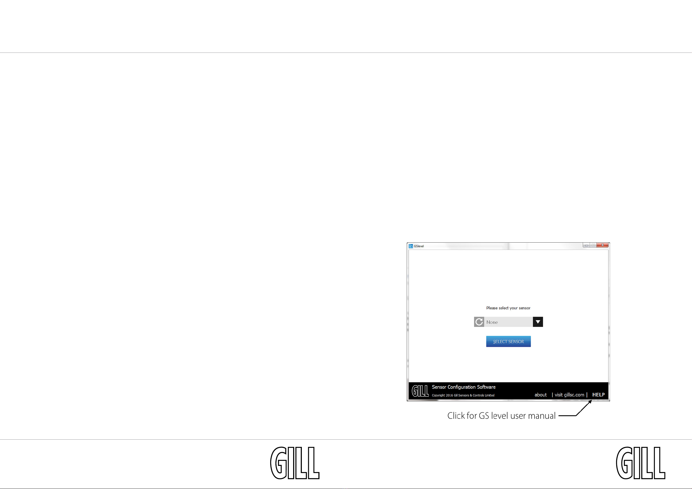
2. Getting started 5
3. Conguration 7
3.1 Tank proling 8
4. Installation 9
4.1 Parts supplied 10
4.2 Cable length & strain relief 10
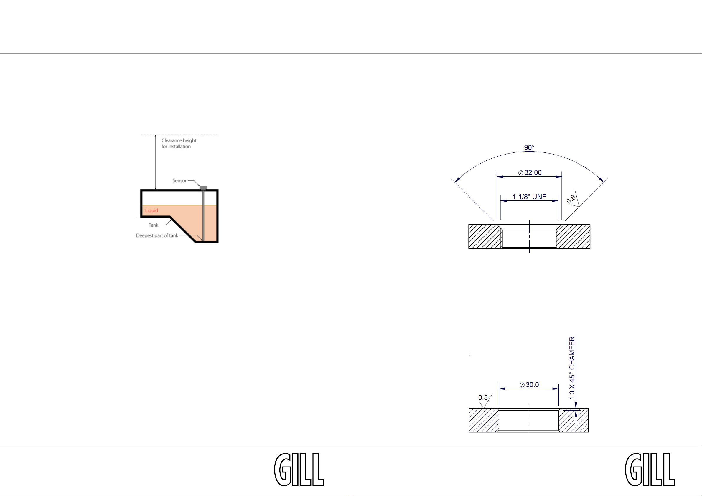
4.3 1.125” UNF Thread installation 10
4.4 1.25” BSP Thread installation 12
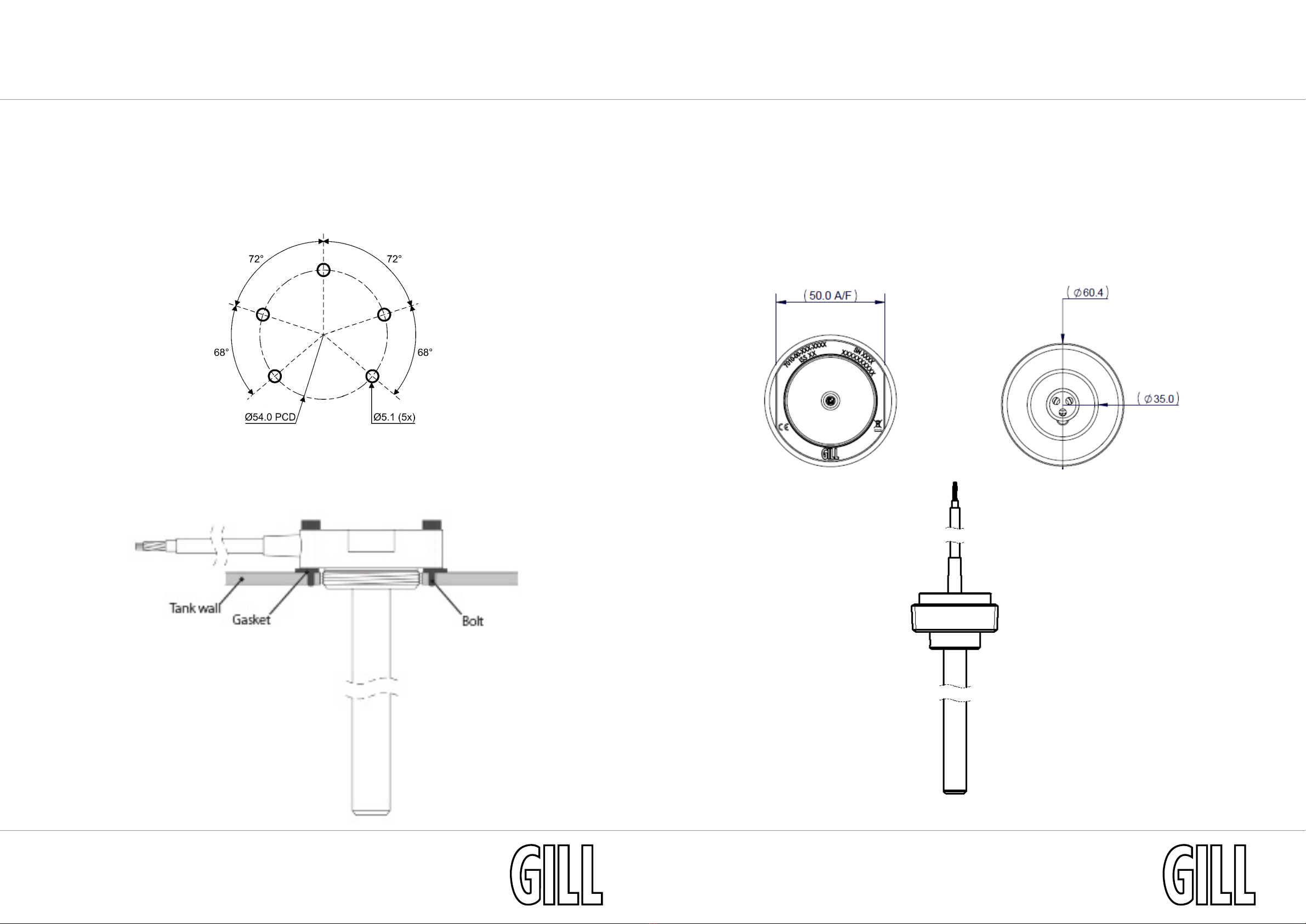
4.5 SAE 5-Bolt installation 14
4.6 2” NPT Thread installation 15
5. Specications 16
5.1 General 16
5.2 Mechanical 16
5.3 Electrical 16
5.4 Analogue outputs 16
5.5 Connections 17
5.6 Part number conguration 17
6. Maintenance, returns & de-commisioning 18
6.1 Maintenance 18
6.2 Returns 18
6.3 Decommonisiong 18
7. Appendix 19
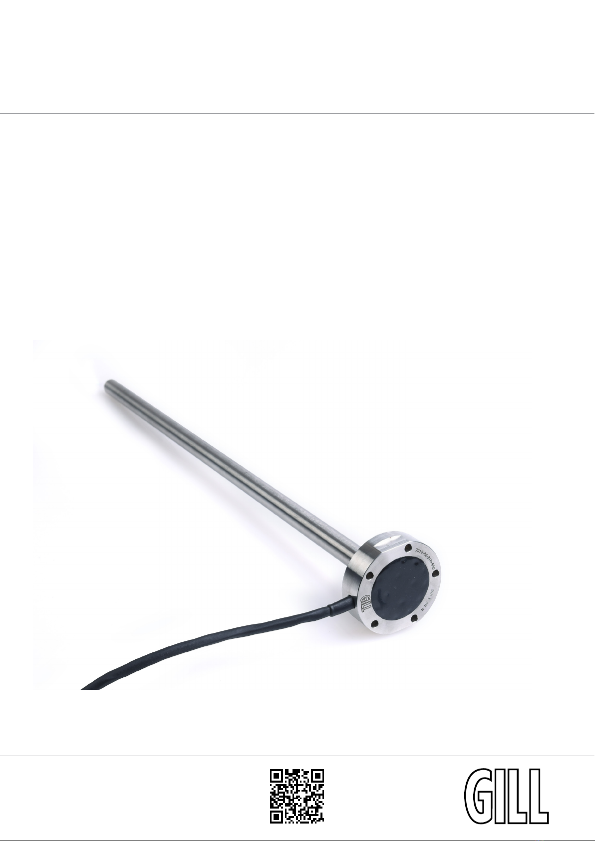
1. Product description
The 7010 Liquid Level Sensor is designed for use in harsh environments at extreme operating temperatures
where the continuous real-time liquid level monitoring of a variety of fuels, oils, chemicals, saline, and water
is required. The sensor has no moving parts, oats or mechanical linkages providing excellent long term
reliability.
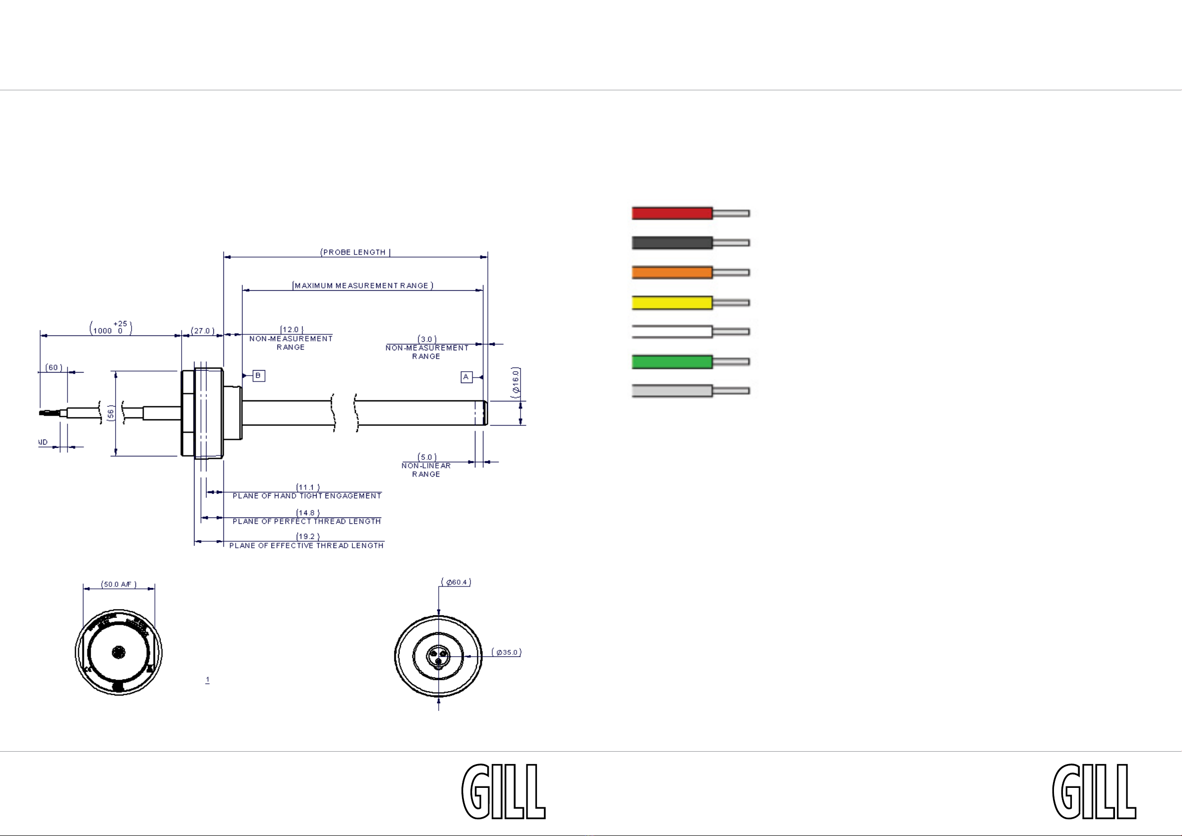
Liquid level detection is achieved through solid-state capacitive technology. An outer tube and inner rod act
as the plates of a capacitor, with any liquid providing the dielectric between the two. As the liquid level rises
and falls, the capacitance of the sensor changes linearly. The on-board electronics process this and provide an
output as a voltage or current signal.
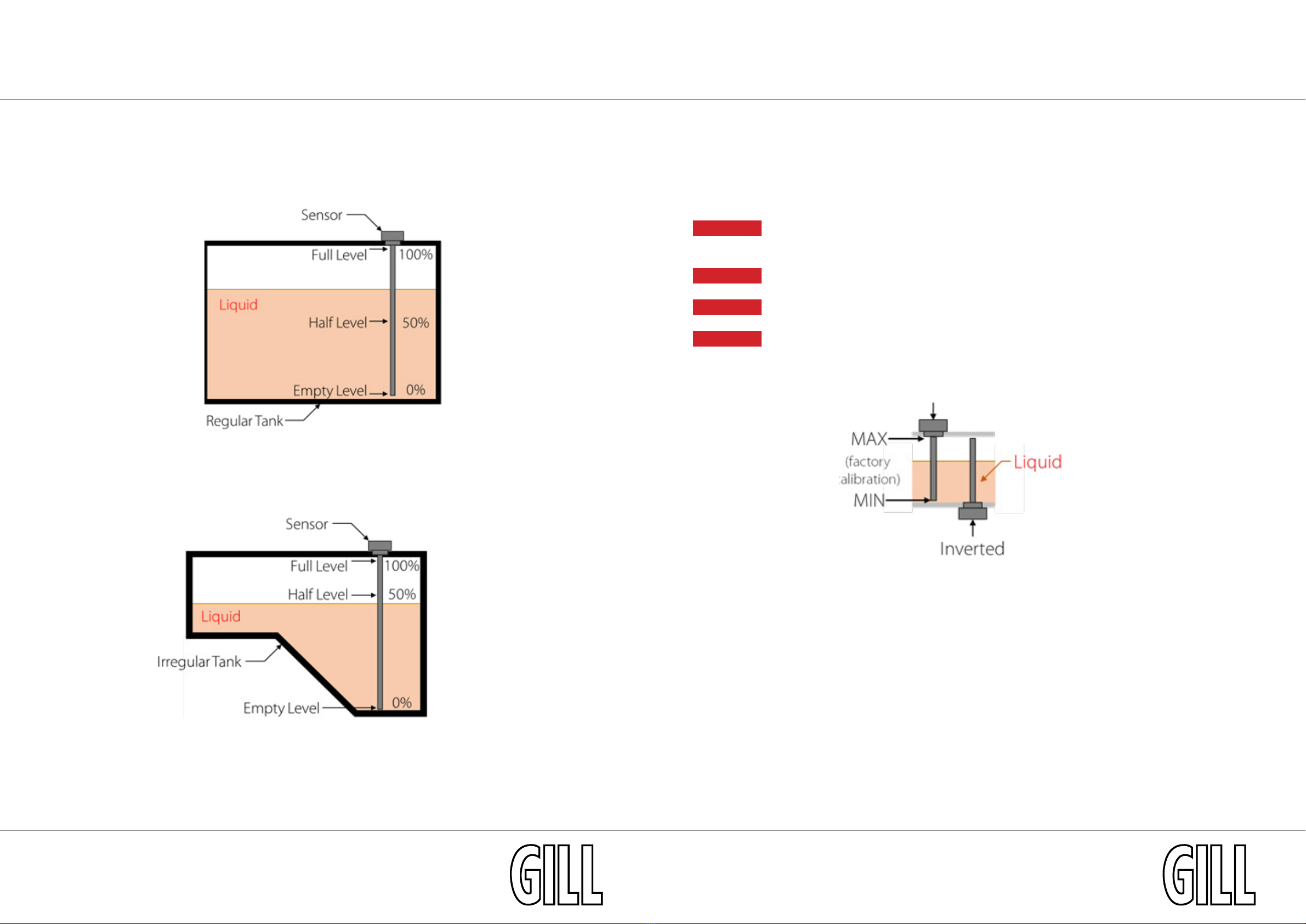
Calibration of the sensor is achieved by setting a maximum (full) and minimum (empty) level for the desired
liquid. The liquid level between these points is determined by proportionally relating the output to the two
set points, while taking account for the dielectric constant value of the liquid.
If requested, further accuracy can be gained by compensating for the eect of temperature changes on the
output in a given liquid with osets across the temperature range.
Your chosen calibration has passed through Gill Sensors & Controls Limited’s quality control to ensure the
sensor provides market leading measurement accuracy in your specied liquid.
The sensor is designed to operate in uids where deposits or build-up of sediment are not expected, as this
may block the bleed holes unless they are regularly maintained. For uids where deposits or build-up of
sediment are expected, please contact Gill Sensors & Controls Limited for a suitable sensor.