Gill WindSonic M 1405-PK-201 User manual

WindSonic M Doc No 1405 PS 0032 Issue 6 August 2021
1

WindSonic M Doc No 1405 PS 0032 Issue 6 August 2021
2
Contents
1FOREWORD4
2INTRODUCTION 4
3FAST TRACK SET-UP 4
4PRINCIPLE OF OPERATION 5
5SPECIFICATION 7
6PRE-INSTALLATION 9
6.1 EQUIPMENT SUPPLIED 9
6.1.1 WindSonic M Analogue Output Part Numbers 9
6.2 PACKAGING 10
6.3 INSTALLATION REQUIREMENTS 10
6.4 CABLE ASSEMBLY 11
7INSTALLATION 14
7.1 INSTALLATION GUIDELINES 14
7.2 BENCH SYSTEM TEST 15
7.3 ELECTRICAL 15
7.3.1 Cable 15
7.3.2 Power supply 16
7.4 CONNECTING TO A PC USING RS232 (DEFAULT SENSOR) 18
7.5 CHANGING A DEFAULT SET WINDSONIC MRS232 OUTPUT (MODE E3) TO RS422
OUTPUT (MODE,E2). 19
7.6 USING SAFE MODE TO CHANGE AN RS422 SET SENSOR BACK TO RS232
OPERATION. 20
7.7 CONNECTING TO A GILL WINDDISPLAY 21
7.8 CONNECTING AN RS422 OUTPUT WINDSONIC MWITH ANALOGUE OUTPUT TO A
PCWITH AN RS422 INTERFACE/CONVERTER. 23
7.9 USING 2WIRE RS485 POINT TO POINT ONLY 24
7.10 ANALOGUE OUTPUT 25
8. Mechanical 26
8.1 ORIENTATION 26
8.2 ALIGNMENT 26
8.3 MOUNTING 26
8.4 EARTHING OR GROUNDING 28
8.5 HEATING 28
9. MESSAGE FORMATS 29
9.1 GILL FORMAT–POLAR,CONTINUOUS (DEFAULT FORMAT) 29
9.2 GILL FORMAT –UV, CONTINUOUS 32
9.3 GILL FORMAT –POLLED (POLAR OR UV) 33
9.4 NMEA FORMAT (NMEA STATUS CODES) 34
9.5 NMEA FORMAT (GILL STATUS CODES) 35
9.6GILL FORMAT –TUNNEL MODE (UU, CONTINUOUS) 35
9.7 ANALOGUE OUTPUTS AND OPTIONS 36
9.7.1 Voltage or Current output 36
9.7.2 Analogue Output Modes 36
9.7.3 Polar mode direction wraparound 36
9.7.4 Wind Speed scaling 37

WindSonic M Doc No 1405 PS 0032 Issue 6 August 2021
3
9.7.5 Tunnel mode 37
9.7.6 Analogue Output Rate 37
9.7.7 Disabled outputs 37
9.7.8 Analogue Output Conditions 37
9.7.9 Low wind speeds (below 0.05 m/s). 38
9.7.10 Error condition reporting 38
10 CONFIGURING 41
10.1 WIND 41
10.2 WINDVIEW 45
10.3 CONFIGURING USING HYPERTERMINAL 50
10.4 ENTERING CONFIGURATION MODE 50
10.5 RETURNING TO MEASUREMENT MODE 50
10.6 CHECKING THE CONFIGURATION 51
10.7 CHANGING A SETTING 51
10.7.1 Command List 52
Bx - Baud rate 53
Cx - settings 53
Dx - Diagnostic and Configuration Command (See Section 10.8) 53
Ex - Communications Protocol 53
Fx - Data and parity options 54
Gx - settings 54
Hx - Power-up Message 54
Kxx to Kxxxx - Minimum Direction Velocity 55
Lx - Message Terminator 55
Mx to Mxx - Message Format 55
Nx - Node Address 55
Ox - ASCII Output Format 56
Px to Pxx - Output Rate 56
Q - Measurement Mode 56
Ux - Output Units 57
Yx –Analogue Output, Error Status Condition 57
10.8 CONFIGURATION /DIAGNOSTIC INFORMATION 58
11 MAINTENANCE & FAULT-FINDING 59
11.1 CLEANING 59
11.2 SERVICING 59
11.3 FAULT FINDING 59
11.4 RETURNING UNIT 60
11.5 STATUS 60
12 TESTS 60
12.1 BENCH TEST 60
12.2 SELF-TEST (STILL AIR) 61
12.3 CALIBRATION 61
13 APPENDICES 62
13.1 GLOSSARY &ABBREVIATIONS 62
13.2 GUARANTEE 62
6.5 FCC 63

WindSonic M Doc No 1405 PS 0032 Issue 6 August 2021
4
1 FOREWORD
Thank you for purchasing the WindSonic M with Analogue Outputs manufactured by Gill
Instruments Ltd. The unit has no customer serviceable parts and requires no calibration or
maintenance. To achieve optimum performance we recommend that you read the whole of
this manual before proceeding with use. Do NOT remove black “rubber” transducer caps.
Gill products are in continuous development and therefore specifications may be subject to
change and design improvements without prior notice.
The information contained in this manual remains the property of Gill Instruments and
should not be copied or reproduced for commercial gain.
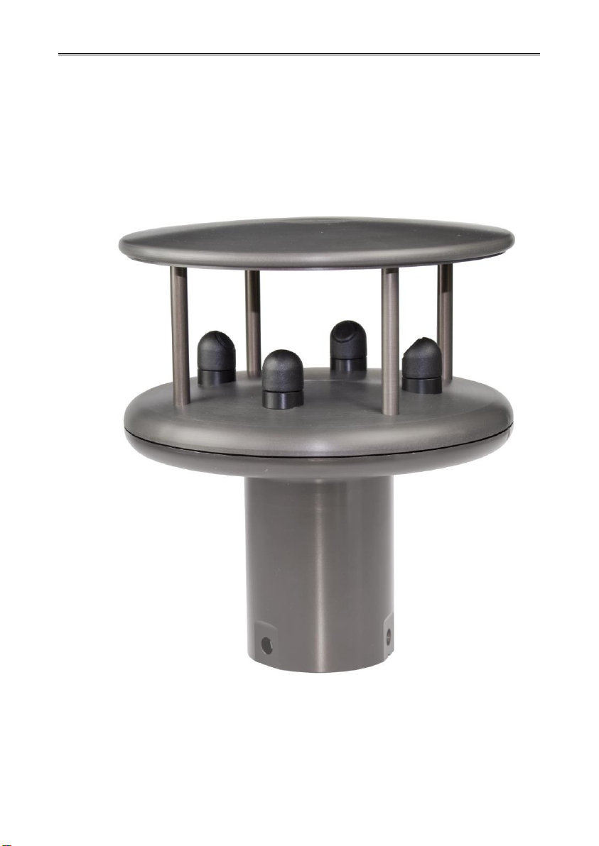
2 INTRODUCTION
With an impressive robust, corrosion-free, aluminium alloy housing and optional anti-icing
heating system the WindSonic M wind sensor is recommended for use in harsh
environmental industrial conditions and is particularly suited to marine, offshore (ships, data
buoys) and land based installations.
The Gill WindSonic M wind sensor has no moving parts, outputting wind speed and
direction. The units of wind speed, output rate and formats are all user selectable.
The WindSonic M can be used in conjunction with a PC, data logger or other device,
provided it is compatible with one of the standard communication formats provided by the
WindSonic M.
WindSonic M set for RS422 output is designed to connect directly to the Gill WindDisplay
unit to provide a complete wind speed direction system.
The WindSonic M part 1405-PK-201(heated) and Part 1405-PK-301 (non-heated) has
analogue outputs to interface to a logger or PLC.
WindSonic M may be configured using Wind software which is available, free of charge,
from the Gill website www.gillinstruments.com. The output message format can be
configured in Gill format, in Polar or UV (2-axis) format, and to either Polled (requested by
host system) or Continuous output. Alternatively, it can be configured in NMEA (0183
Version 3). These are described in Section 9 MESSAGE FORMATS.
3 FAST TRACK SET-UP
If you are in a hurry to try out the WindSonic M and are familiar with Gill equipment and
coupling to a PC using RS232, go to the following sections:
Section 7 INSTALLATION
Section 9 MESSAGE FORMATS
Section 10 CONFIGURING
After you have successfully set up the WindSonic M, we strongly advise that you then go
back and read the rest of the manual to ensure that you get the best results from the
WindSonic M.

WindSonic M Doc No 1405 PS 0032 Issue 6 August 2021
5
4 PRINCIPLE OF OPERATION
The WindSonic M measures the times taken for an ultrasonic pulse of sound to travel from
the North transducer to the South transducer, and compares it with the time for a pulse to
travel from S to N transducer. Likewise times are compared between West and East, and E
and W transducer.
If, for example, a North wind is blowing, then the time taken for the pulse to travel from N
to S will be faster than from S to N, whereas the W to E, and E to W times will be the same.
The wind speed and direction can then be calculated from the differences in the times of
flight on each axis. This calculation is independent of factors such as temperature.
Figure 1 Time of Flight details

WindSonic M Doc No 1405 PS 0032 Issue 6 August 2021
6
Figure 2 Compass Points

WindSonic M Doc No 1405 PS 0032 Issue 6 August 2021
7
5 SPECIFICATION
This Specification relates to WindSonic M Sensor Part Numbers 1405-PK-201/301.
Output
Units of measure
Metres/second (m/s), Knots, Miles per hour (mph),
Kilometres per hour (kph), Feet per minute (fpm)
Output frequency
0.25, 0.5, 1, 2, or 4 outputs per second
Digital Output
Parameters
Polar - Speed and Direction
UV - 2 axis, signed Speed
NMEA Speed and Direction
Tunnel - U speed & U Polarity
Wind Speed
Range
0 –60m/s,
Accuracy
2% (at 12m/s)
Resolution
0.01 m/s
Wind Direction
Range
0 - 359
Accuracy
3(at 12m/s)
Resolution
1
Analogue output
formats
0-5V
4-20mA
0-20mA
1% of full scale N.B. Analogue output impedance = 1KΩ (V out)
Load resistance between the Analogue outputs (Pins L & M) and
Signal Ground (Pin K) must be <= 300 ohms, including cable
resistance.
Digital output formats
Gill ASCII
Continuous or Polled (output on request by host system)
Polar (Speed and Direction) or UV (2 axis, signed Speed)
Marine –NMEA
NMEA 0183 version 3
Tunnel
Tunnel - U speed & U Polarity
Communication
formats
Data Levels
RS232, RS422 and RS485 (2 wire Point to Point only)
Baud Rates
2400, 4800, 9600, 19200, 38400
Anemometer status
Status OK and error codes (not for heating) included in output message
Power requirement
Sensor Power
Sensor Power 5V to 30V dc.
Sensor Current 9mA @ 12V DC (1Hz, 9600B, RS232).
Sensor Current 5.5mA @ 12V DC (0.25Hz, 9600B, RS232).
Sensor Current increases if Analogue Current outputs are selected, add up
to 40mA to nominal readings above.
Heater Power
(For Part Number
1405-PK-201)
Heater Power 10V to 30V DC.
Heater Power 24V rms AC 10 % @50/60Hz.
Heater Current Allow for 2.2 Amps @ 12V DC nominal (26W max.).
Heater Current Allow for 4.2 Amps @24v AC or DC nominal (100W
max.).

WindSonic M Doc No 1405 PS 0032 Issue 6 August 2021
8
Mechanical
Size / Weight
Size 142mm diameter x 163mm Weight 0.9kg.
Mounting
Pipe mounting 1.75 inches (44.45mm) diameter.
Material
External –Aluminium Alloy 6061T6 or T4, hard anodise finish.
Connector –Nickel Plated Brass.
Environmental
Moisture protection
IP66
Operating Temperature
Operating -35C to +70C Unit without Heating.
Operating -40C to +70C Unit with Heating.
Storage Temperature
Storage -40C to +80C
Humidity
Operating <5% to 100%
Hail
UL2218 Class 1
EMC
EN 61326:1998 and BSEN 60945
FCC CFR47 Parts 15.109 Class A
Standards
Manufactured within ISO9001: 2000 quality system

WindSonic M Doc No 1405 PS 0032 Issue 6 August 2021
9
6 PRE-INSTALLATION
6.1Equipment supplied
Item
Quantity
WindSonic M
1
12 Way connector and Mounting Screws as follows:-
12 Way Connector Body
1
Connector Contacts
12
Connector Backshell
1
Mounting Screws –M5 stainless steel
3
Mounting Screw M5 Washer shake proof
3
Earthing Screw –M4 x 6 Stainless
1
Earthing Shakeproof Washer, M4
1
Earthing Ring Terminal Tag, M4
1
The User Manual, Wind and WindView software are also available free of charge from the
Gill website –www.gillinstruments.com
6.1.1 WindSonic M Analogue Output Part Numbers
1405-PK-201 WindSonic M –Analogue Outputs and Heating, RS 232/422/485 point to
point digital outputs.
1405-PK-301 WindSonic M –Analogue Outputs, No Heating , RS 232/422/485 point to
point digital outputs.
Optional extras:
Item
Part Number
Cable 4 Pair twisted and shielded wires, 24 AWG, per metre.
026-03156
Cable 3 Pair twisted and shielded wires, 24 AWG, per metre.
026-02660
WindSonic M 12 way connector parts (1 supplied as standard
see above)
1405-PK-112
WindSonic M Support Tube, 0.5M (Aluminium)
1405-30-056
15M Cable, 4 Pairs twisted and shielded, 24AWG, clipper
pins fitted one end, tinned wires the other.
1405-10-080

WindSonic M Doc No 1405 PS 0032 Issue 6 August 2021
10
6.2Packaging
Whilst the WindSonic M is being moved to its installation site, the unit should be kept in its
inner packaging. All the packaging should be retained for use if the unit has to be returned at
any time, or if a self-test is performed.
6.3Installation requirements
Host system - Use of the following:
PC fitted with a suitable interface to match the chosen communication format
(RS232, RS422, or RS485 point to point only) compatible with the
WindSonic M option selected and a suitable Terminal Emulation software
package. For example HyperTerminal for Windows.
Gill Wind software can be used for WindSonic M configuration and is
available from the Gill website. It will also run on Vista, Windows 7,8 and 10
PC’s and can be used as a Terminal Program if required.
Gill WindDisplay (WindSonic M set for RS422 output).
Other equipment with input/output compatibility to the WindSonic M.
For example, Data logger.
Cable - To connect between the WindSonic M and the host system
See Section 7.3.1 Cable type for cable specification.
There are restrictions on the maximum cable lengths for correct operation.
The cable should be routed up the inside of the mounting tube.
Mounting tube
Standard tube 1.75 inches (44.45mm) Outside Diameter x 3mm wall
thickness. Note it is important that the correct diameter tube is used.
See Figure 3 in section 8.3 Mounting Details
For non-hostile environments, Aluminium tube can be used.
For hostile environments, you should select a material suitable for the
intended environment. For example, stainless steel 316 for marine use.

WindSonic M Doc No 1405 PS 0032 Issue 6 August 2021
11
6.4Cable Assembly
The WindSonic M with analogue outputs is supplied with a mating 12 way connector.
Open the pack of connector parts supplied (Gill Part 1405-PK-112).
A set of assembly instructions are supplied with the connector together with:-.
Table of Equivalent Part Numbers
Part Name
Gill Part No.
Cannon Trident Part No.
Connector head, 12 way
020-04990
192993-0053
Metal backshell (7 pieces)
020-04991
192993-0083
Solder bucket contacts
(5 per pack, (3 –off packs))
020-04469
192900-0635
Arrange Backshell (Gill Part Number 020-04991).
Pass parts 1-6 along the cable as per the diagram below.
(Note that the connector supplies the correct strain relief for cables with an outside diameter
of 6.9 to 10.2mm).
Prepare Cable.
Trim back the cable outer and twisted pair screen sleeves 40mm (see diagram below).
Trim back the screen drain wires to a length of 24mm.
Strip back the connection wires by 7.1mm and tin solder.
Solder the bucket contacts to the wires.
Unused wires should be cut back and insulated.
7.1mm
40 mm
Screen drain wires
Screen Twisted Pair Cable
24mm
Part 1
Part 2
Part 3
Part 4
Part 7
Part 6
Part 5
Part 1

WindSonic M Doc No 1405 PS 0032 Issue 6 August 2021
12
Prepare Connector Head (Gill Part 020-04990).
Remove the connector thread protector and place the O-ring (part 7) into the groove of the
connector head (020-04990).
Assemble Connector to the Cable.
Push connector contacts through the red connector head seal into the appropriate location,
when in place there should be a click as the contact locks into position.
Once contacts are in position pass part 6 up the cable and into position as shown below.
Note: if a connector pin needs removing use Cannon Extraction Tool, Manufacturer’s
Part 192922-1450.
Fold and spread screen wires over part 6 and then push up part 5 as shown to clamp screen
wires between Parts 5 and 6.
O-Ring to be placed around here
Remove the thread protector
Part 5
Part 6
Part 6

WindSonic M Doc No 1405 PS 0032 Issue 6 August 2021
13
Now screw in part 4 and torque up to a value of 10Nm.
Pass parts 3 and 2, the cable seal and cable grip from the connector kit, along the cable to the
housing.
Now screw in item 1, the clamp nut, over parts 2 and 3 and onto the housing and torque up
to a value of 10Nm.
Part 2
Part 4
Part 1
Part 3

WindSonic M Doc No 1405 PS 0032 Issue 6 August 2021
14
7 INSTALLATION
Do NOT remove the black “rubber” transducer caps. Warranty is void if the coloured
security seal is damaged or removed.
7.1Installation Guidelines
The WindSonic M has been designed to meet and exceed the stringent standards listed in its
specification. Operating in diverse environments all over the world, WindSonic M requires
no calibration and adjustment whatsoever.
As with any sophisticated electronics, good engineering practice should be followed to
ensure correct operation.
Always check the installation to ensure the WindSonic M is not affected by other
equipment operating locally, which may not conform to current standards, e.g.
radio/radar transmitters, boat engines, generators etc.
Guidelines –
oAvoid mounting in the plane of any radar scanner –a vertical separation
of at least 2m should be achieved.
oRadio transmitting antennas, the following minimum separations (all
round) are suggested
VHF IMM –1m
MF/HF –5m
Satcom –5m (avoid likely lines of sight)
Use cables recommended by Gill. If cables are cut and re-connected incorrectly
(perhaps in a junction box) then EMC performance may be compromised if cable
screen integrity is not maintained.
Earth loops should not be created –wire the system in accordance with the
installation guidelines.
Ensure the power supply operates to the WindSonic M specification at all times.
Avoid turbulence caused by surrounding structures that will affect the accuracy of the
WindSonic M such as trees, masts and buildings. Ideally sensors should be mounted on the
prevailing wind side of the site.
The WMO make the following recommendations:
The standard exposure of wind instruments over level open terrain is 10m above the
ground. Open terrain is defined as an area where the distance between the sensor and
any obstruction is at least 10 times the height of the obstruction.
If mounting on a building then theoretically the sensor should be mounted at a height of 1.5
times the height of the building.
If the sensor is to be mounted on a mast boom, part way up a tower or mast, then the boom
should be at least twice as long as the minimum diameter or diagonal of the tower. The
boom should be positioned on the prevailing wind side of the tower.

WindSonic M Doc No 1405 PS 0032 Issue 6 August 2021
15
7.2Bench system test
Note: Prior to physically mounting the WindSonic M in its final location, we strongly
recommend that a bench system test is carried out to confirm the system is configured
correctly, is fully functional and electrically compatible with the selected host system and
cabling (preferably utilising the final cable length). The required data format, units, output
rate, and other options should also all be set up at this stage.
7.3Electrical
7.3.1 Cable
Cable type
An RS422 compatible cable should be used for data communications, with the number of
twisted pairs matching the application.
Generic description –Twisted pairs with drain wire, screened with aluminised tape,
with an overall PVC sheath. Wire size 7/0.2mm (20-24 AWG).
The tables below show some suitable manufacturers’ references; other manufacturers’
equivalents can be used.
WindSonic M, Analogue Output, Non-Heated
Application
No. of pairs
Gill.
24 AWG
Belden.
24 AWG
Batt
electronics.
24 AWG
WindDisplay
2
-
9729
-
RS 232
3
026-02660
9730
91030
RS 422/485
4
026-03156
9728
91199
Analogue only
3
026-02660
9730
91030
WindSonic M, Analogue Output, Heated
Thicker or higher specification cable can be used up to 20 AWG. If long cables are used
then consideration should be given to powering the Heater using lower 20 AWG gauge
wire or paralleling heater and sensor power cables (24v dc supply only) to reduce volt
drops.
Alternatively locate the sensor/heater supply as close as possible to the unit and run data
only over the longer cable distances.
Application
No. of pairs
Gill.
24 AWG
Belden.
24 AWG
Batt
electronics.
24 AWG
WindDisplay
3
026-02660
9730
91030
RS 232
4
026-03156
9728
91199
RS 422/485
6
026-02661
9731
91031
Analogue only
4
026-03156
9728
91199

WindSonic M Doc No 1405 PS 0032 Issue 6 August 2021
16
Cable length
The maximum cable length is dependent on the chosen communication format (RS232,
RS422 or RS485 (point to point)), the baud rate, and, to a lesser extent, on the cable type and
the local electrical ‘noise’ level.
The table shows the typical maximum lengths at the given baud rates, using the
recommended cable. If any problems of data corruption etc. are experienced, then a slower
baud rate should be used. Alternatively, a thicker or higher specification cable can be tried.
For Heater cable lengths advice refer to the previous Cable Type Section.
Communication format
Baud rate
Max. cable length
RS232
9600
6.5 m (20 ft.)
RS422 or 485 (P to P)
9600
1 km (3200 ft.)
Analogue Voltage Output
Not
Applicable
6.5m (20ft)
Analogue Current Output
Not
Applicable
Resistance dependant.
Cable resistance and
load to be less than 300
ohms.
7.3.2 Power supply
Wind Sensor
WindSonic M Sensor Supply 5V to 30V DC (30V DC max).
WindSonic M Sensor Current 9mA @ 12V DC (1Hz, 9600B, RS232).
WindSonic M Sensor Current 5.5mA @ 12v DC (0.25Hz, 9600B, RS232).
Add up to a further 40mA if Analogue current outputs are selected.
Heating (Part 1405-PK-201)
Heater Power 10V to 30.0V DC.
Heater Power 24V rms AC 10 % @50/60Hz.
Heater Current Allow for 2.2 Amps @ 12V DC (nominal supply), 26W max.
Heater Current Allow for 4.2 Amps @24v AC or DC (nominal supply) 100W max.
Heater Current Non activated standby current approximately 40mA.
Heater Cable length should be minimised to avoid cable volt drops and ensure
maximum voltage is received at the Anemometer.
A 24v dc Heater Supply capable of a minimum of 6 Amps is recommended for initial
heating start up surge.
Note that the Heater supply is isolated from the Sensor supply.
However it is permissible to connect a common 24v dc supply to both the Sensor supply
connections and Heater supply connections if required.

WindSonic M Doc No 1405 PS 0032 Issue 6 August 2021
17
Neither the Sensor supply connections or the Heater supply connections should be connected
to the WindSonic M metal case.
Heater Cable length should be minimised to avoid cable volt drops and ensure maximum
voltage is received at the Anemometer.
If necessary parallel up spare wires in the cable and connect to the heater pins in order to
reduce volt drops.
There is no heating command on the heated WindSonic M, heating is enabled by internal
temperature sensing devices and cannot be disabled except by removing the heater supply.
The WindSonic M has reverse polarity protection.

WindSonic M Doc No 1405 PS 0032 Issue 6 August 2021
18
7.4Connecting to a PC using RS232 (Default Sensor)
Notes.
1. Some PCs may have a Serial RS232 interface and a suitable terminal emulation
package already installed, which can be utilised with the WindSonic M. (e.g.
HyperTerminal or equivalent). Otherwise use Gill Wind Software.
2. The cable length for reliable operation is limited to 6.5m (20ft).
(See Section 7.3.1 Cable length.)
3. For longer cable runs, we recommend using the WindSonic M configured with RS422
output, and a RS422/232/USB converter at the PC. See Para 7.8 Connecting an RS422
output WindSonic M with Analogue Output to a PC with an RS422 Interface/.
WindSonic M
12 Way Connector
Cable -Twisted
Pairs
PC
Typical 9 Way ‘D’ Connector
Signal names
Pin
Signal names
Pin no's
Chassis Ground
A
Chassis Ground
N/A
TXD
RXD
E
G
RXD
TXD
2
3
Signal Ground
5
Sensor Power +ve
Sensor Power –ve
and Signal Ground
B
C
+ve
-ve
DC Power Supply
(See Para 7.3.2)
An. Speed Ch 1
An. Direction Ch 2
Signal Ground
L
M
K
Ch1 Input Analogue Device
Ch2 input
Channel 1/2 Return
Heater Power +ve
(1405-PK-201)
Heater Power –ve
H
J
+ve
-ve
Optional DC or AC
Heater Supply
(see Para 7.3.2)
Default Settings
The WindSonic M unit is factory configured with the following default settings:
M2, U1, O1, L1, P1, B3, H1, NQ, F1, E3, T1, S4, C2, G0, K50
Screen/Drain Wires

WindSonic M Doc No 1405 PS 0032 Issue 6 August 2021
19
7.5Changing a Default Set WindSonic M RS232 Output
(Mode E3) to RS422 Output (Mode, E2).
WindSonic M
12 Way Connector
PC
Typical 9 Way ‘D’ Connector
Signal names
Pin
Cable –twisted
pairs
Signal names
Pin no's
Chassis
Ground
A
Chassis
Ground
N/A
TXD
RXD
E
G
RXD
TXD
2
3
Signal Ground
5
Sensor Power
+ve
Sensor Power
–ve
and Signal
Ground
B
C
+ve
-ve
DC Power Supply
(See Para 7.3.2)
Connect the WindSonic M as per the above diagram.
With WindSonic M power off, set up a HyperTerminal (or equivalent) connection as per
Para 10.3 but with the Baud rate set to 19200 (this can be at variance with the original
WindSonic M Baud rate setting).
Hold down the * character (shift 8) and then apply power to the WindSonic M.
After approximately 3 seconds the unit will respond with Safe Mode.
Remove any * characters on screen or press Enter.
Type E2 and press Enter (changes E3 setting to E2 (RS422)).
E2 will be seen twice on screen to confirm the setting change to RS422 has occurred.
It is possible to make other configuration setting changes now if required.
Type Q and press Enter to go back into measurement mode.
Now wire the WindSonic M to an RS422 device.
If a new terminal connection is required the Baud rate setting will be as per the WindSonic
M configuration setting.
Screen/Drain Wires
Other manuals for WindSonic M 1405-PK-201
1
This manual suits for next models
1
Table of contents
Other Gill Measuring Instrument manuals

Gill
Gill WindObserver 65 User manual

Gill
Gill HS-50 User manual

Gill
Gill WindUltra User manual

Gill
Gill MetPak 1723-1B-2-111 User manual

Gill
Gill R3-50 User manual

Gill
Gill WindSonic M 1405-PK-201 User manual

Gill
Gill E73708 Reference guide

Gill
Gill WindMaster Pro User manual

Gill
Gill TCT-1000 User manual

Gill
Gill WindSonic User manual