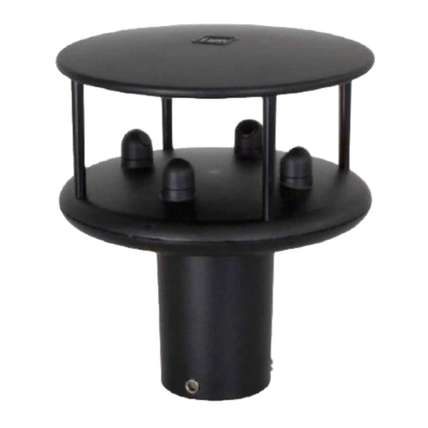
R3-50, R3-100 and R3A-100 Doc. No 1210-PS-0015 Issue 2 June 2021
___________________________________________________________________________________________
Page 1
1FOREWORD..................................................................................................................3
2INTRODUCTION..........................................................................................................3
3PACKING LIST.............................................................................................................4
4OPTIONAL EXTRAS ...................................................................................................4
5PRINCIPLE OF OPERATION....................................................................................5
6TECHNICAL SPECIFICATION.................................................................................6
7INSTALLATION...........................................................................................................7
7.1 Installation Guidelines..................................................................................................................... 7
7.2 Mounting............................................................................................................................................ 7
7.3 Alignment .......................................................................................................................................... 7
7.4 Polar definition.................................................................................................................................. 7
7.5 U, V, and W axes definition............................................................................................................ 7
7.6 Orientation......................................................................................................................................... 9
7.7 Alignment and Dimensions............................................................................................................. 9
7.8 Mechanical installation.................................................................................................................. 11
7.9 Location........................................................................................................................................... 11
7.10 Corrosion..................................................................................................................................... 11
7.11 Earthing....................................................................................................................................... 11
7.12 Mounting Base............................................................................................................................ 12
7.13 Flange Mounting ........................................................................................................................ 12
7.14 Cabling......................................................................................................................................... 13
7.15 Cable length................................................................................................................................ 13
7.16 20 Way Hirose Connector......................................................................................................... 14
8OPERATION................................................................................................................15
8.1 Overview ......................................................................................................................................... 15
8.2 Operating modes............................................................................................................................ 15
8.3 Measurement Mode....................................................................................................................... 15
8.4 Sampling ......................................................................................................................................... 15
8.5 Averaging (and Output Rate)....................................................................................................... 15
8.6 Wind Measurement, SoS and Temperature Reporting Format .............................................. 16
8.7 Analogue Input Reporting Formats ............................................................................................. 16
8.8 Diagnostics ..................................................................................................................................... 16
8.9 Confidence Tone............................................................................................................................ 16
8.10 Result Reporting ........................................................................................................................ 16
8.11 Interactive Mode......................................................................................................................... 17
8.12 Configuration Commands......................................................................................................... 17
8.13 Default Configuration Command Settings.............................................................................. 17
8.14 Default Output Data String ....................................................................................................... 17
8.15 Interrogation Commands .......................................................................................................... 17
9CONNECTION TO A PC OR OTHER DEVICE ....................................................18
9.1 Anemometer Connector / SIU Power and Data Connector..................................................... 18
10 CONNECTING R3 TO A PC USING RS422 ........................................................19
10.1 Connecting R3 to a PC via Optional Power and Communications Interface (PCI 1189-
PK-021 or PCIA 1189-PK-020)................................................................................................................ 19
10.1.1 Environmental......................................................................................................................... 19
10.1.2 PCI/PCIA Electrical Power Requirements.......................................................................... 20
10.1.3 PCI/PCIA Operation. ............................................................................................................. 20
10.1.4 PCIA Box (1189-PK-020) R3 Analogue Output Connections. ........................................ 22
10.1.5 Gill Instruments R3/SIU to PCI/A Ready Made Gill Cable 1210-PK-043 ...................... 23
11 SYSTEM CONNECTION DIAGRAMS ................................................................25
11.1 Basic System Connection......................................................................................................... 25
11.2 System Connection Including Optional SIU........................................................................... 26
11.3 Interface Cable Connections.................................................................................................... 27
11.4 1210-00-011 Interface Cable ................................................................................................... 28
12 USING ANALOGUE INPUTS WITH SENSOR INPUT UNIT PART 1210-PK-
016 .....................................................................................................................................29
12.1 Analogue Inputs ......................................................................................................................... 29
12.2 Using the SIU PRT Input........................................................................................................... 30
12.3 1210-K-067 Sensor Input Unit Mounting Details................................................................... 31
