Gillison's Variety Fabrication Tier IV GL 11491 User manual

Tier IV
GVF Rough Terrain Forklift
Owners Manual
Model Numbers:
TIER IV
GVF 5000
GVF 6000
GVF 8000
Manual Part Number:
GL 11491
3033 B
enzie
H
wy
. B
enzonia
, Mi 49616 231-882-5921
Fax 231-882-5637 800-392-6059
Gillison’s Va r i e t y
Fabrication, Inc.
online: www.gillisons.com
GVF
PREVIOUS
NEXT
LAST
INDEX

Table of Contents
TABLE OF CONTENTS
INTRODUCTION 1
SAFETY 2
Forklift Mast Safety 16
Fork Safety 11
General Safety Rules 3
General Safety While Operating 4
Instruction Decals 8
Intro to safety 2
Load Handling Safety 9
Modications 10
OwnershipRecords 10
RecordRetention 10
RulesoftheRoad 10
Safety Alert Symbol 2
Safety While Operating 9
Safety While Servicing the Machine 5
Serial Number 9
Signal Words 2
CONTROLS 17
Display Screen Information 18
Display Screen - Pop Up Warning Lights 21
Instrument Panel Diagram 17
Various Controls 25
OPERATION 28
Cold Weather Starting 28
Forklift Shutdown 28
Operating GVF Forklift 28
Pre Start Up 28
Starting The Engine 28
LUBRICATION & MAINTENANCE 30
Grease Points 32
Hydraulic System 54
Instructions for Pressure Washing 34
Lubrication&MaintenanceChart 30
Lubrication & Maintenance Reference Diagram 31
Mast Maintenance 49
PD70FrontAxle 41
SD55RearAxle 43
ELECTRICAL 56
REFERENCE 63
Filter Part Numbers 63
Manuals 63
GVF WARRANTY 64
PREVIOUS
NEXT
LAST
INDEX

GVF Rough TerrainTier IV Forklift Manual INTRODUCTION - 1
INTRODUCTION
The information in this publication describes the safety
requirements, operation, maintenance and servicing
of the Gillison Forklift. Every effort has been made to
provide correct and concise information to you, the
operator, as available at the date of publication. Your
Gillison dealer is available should items in this book or
details of your machine not be understood.
This book is supplied with each machine to familiarize
the operator with proper instructions needed for
operation and maintenance. Studying and adhering
to these instructions will insure optimum machine
performance and longevity.A machine that is maintained
properly and operated in the intended manner will
provide greater dividends than one that is neglected
and/or operated in a manner other than as intended.
Design and servicing of this machine has been kept as
simple as possible to permit maintenance operations to
be carried out with tools normally available.
This book should be thoroughly read and understood
prior to operation of this machine. Inexperienced
operators should study contents of this publication
andreceiveinstructionfromanexperiencedoperator
when possible. Your Gillison dealer can assist in areas
concerning machine operation and provide details
concerning safe operation. It is suggested that this
booklet be kept readily accessible, preferably with the
machine, for future reference if questions or concerns
arise. If the original book should become lost or
damaged, consult your Gillison dealer in regards to
acquiring a replacement.
Customers are strongly advised to use an authorized
Gillison dealer in connection with any service problems
and adjustments that may occur.
CAUTION: READ THIS BOOK
IN ITS ENTIRETY PRIOR TO
OPERATING THE MACHINE. Use
only parts from your Gillison dealer
for repairs and/or replacement.
GVF Tier IV Turbo Rough Terrain Forklift
PREVIOUS
NEXT
LAST
INDEX

- SAFETY2GVF Rough TerrainTier IV Forklift Manual
SAFETY
INTRO TO SAFETY
The safety of the operator is one of the main concerns
in designing a new piece of equipment. Designers
build in as many safety features as possible. However,
every year many accidents occur which could have
been avoided by a few seconds of thought and a more
careful approach to handling equipment. You, the
operator, can avoid many accidents by observing the
following precautions. To avoid personal injury, study
the following precautions and insist those working with
you or for you to follow them.
In order to provide a better view, certain photographs
or illustrations in this manual may show an assembly
with a safety shield removed. However, the equipment
should never be operated in this condition. Keep all
shields in place. If shield removal becomes necessary
for repairs, replace shield prior to further operation.
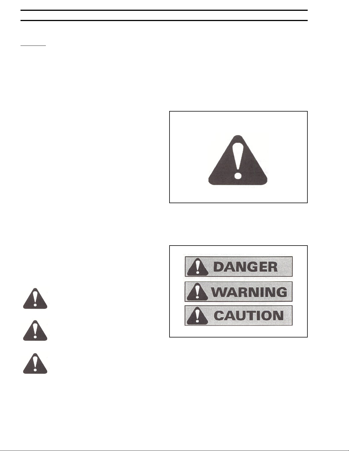
SAFETY ALERT SYMBOL
FIG. 1: This is the safety alert symbol. It means
ATTENTION! BECOME ALERT! YOUR SAFETY IS
INVOLVED! Look for it, both in this manual and on
safety decals on the equipment. It will direct your
attention to information that involves your safety and
the safety of others.
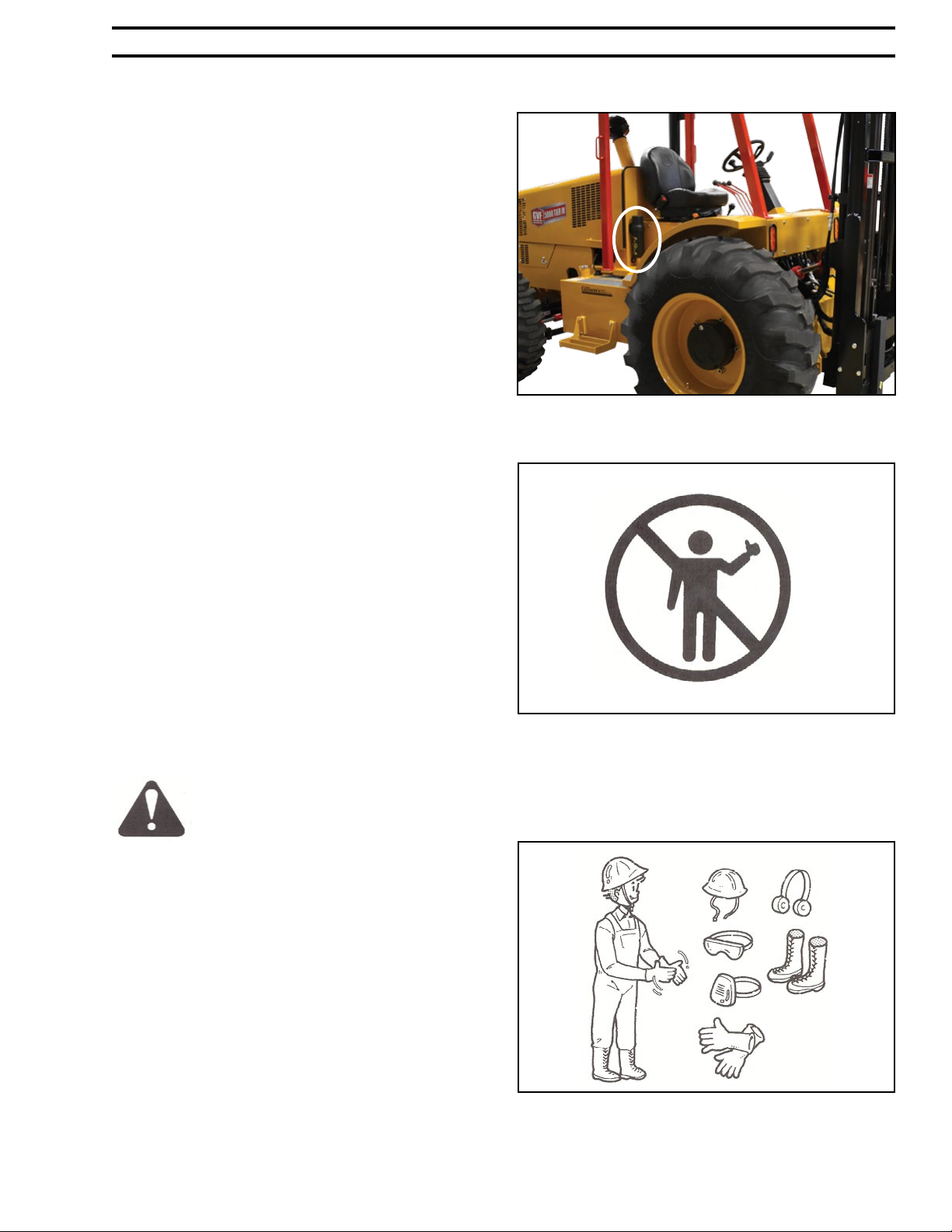
SIGNAL WORDS
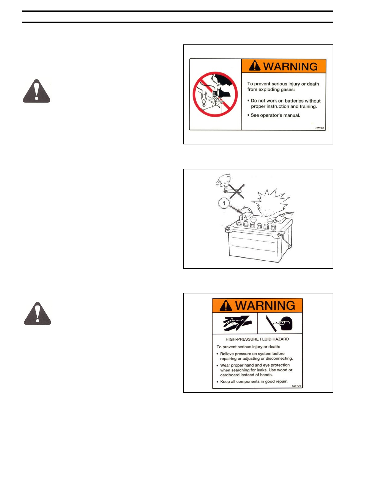
FIG.2:The words DANGER,WARNING,or CAUTION
are used with the safety alert symbol.Learn to recognize
these safety alerts, and follow the recommended
precautions and safe practices.
DANGER indicates an imminently
hazardous situation that, if not
avoided,will result in death or serious
injury.
WARNING indicates an imminently
hazardous situation that, if not
avoided, could result in death or
serious injury.
CAUTION indicates an imminently
hazardous situation that, if not
avoided, may result in minor or
moderate injury.
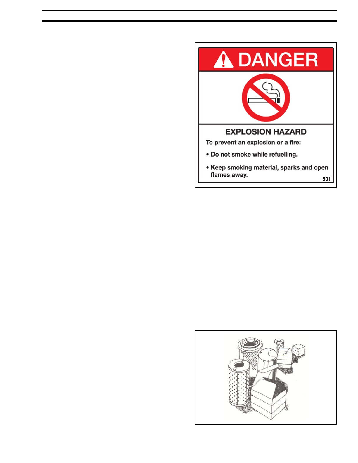
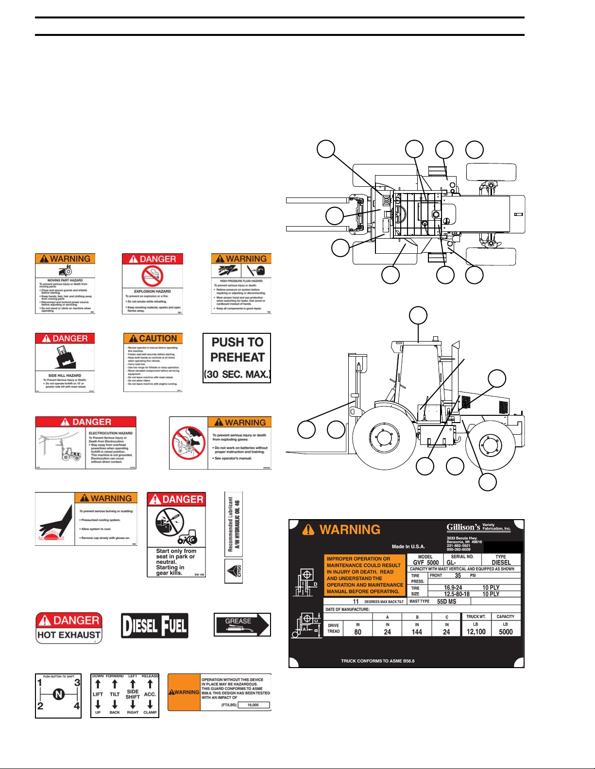
Replace any DANGER, WARNING, CAUTION or
instructional decal that is not readable or is missing.
The locations and part numbers of these decals are
identiedlaterinthissectionofthemanual.
FIG. 1
FIG. 2
PREVIOUS
NEXT
LAST
INDEX

SAFETY - 3
GVF Rough TerrainTier IV Forklift Manual
GENERAL SAFETY RULES
FIG. 3: Always keep this manual with the machine.This
manual must be made available to the operator of the
machine at all times. Special care must be taken to
keep this manual safe from the weather and in readable
condition.
Read this manual carefully and learn how to use the
machine correctly.
Do not let anyone operate this machine without
thorough instruction.
Beware of bystanders, particularly children! Always
look around to make sure that everyone is clear before
starting the engine or moving the machine. This is
particularly important with higher noise levels as you
may not hear people shouting.
FIG. 4: No passengers allowed. Do not carry passengers
anywhere on the machine.
Dismount and park machine in the correct manner.
When dismounting and/or leaving the operator’s
platform FOR ANY REASON always:
1. Shift to Neutral.
2. Come to a complete stop.
3. Lower forks completely.
4. Park on level ground.
5.Activate parking brake.
6. Shut off engine and remove key.
WARNING: An operator should not
use alcohol or drugs which can affect
their alertness or coordination. An
operator on prescription or ‘over
the counter’ drugs needs medical
advice on whether or not he/she can
properly operate equipment.
FIG. 5: Wear protective clothing. Do not wear loose
clothing, as this may catch on moving parts of the
machine causing injury.
Always wear protective clothing and appropriate safety
equipment.
It is recommended that suitable protective hearing and
safety glasses be worn.
Do not attempt to service machine, clear obstructions
or unplug blockages with the engine running. Always
shutofftheenginerst.
Keep all shields and guards in place.
FIG. 3
FIG. 4
FIG. 5
PREVIOUS
NEXT
LAST
INDEX

- SAFETY4GVF Rough TerrainTier IV Forklift Manual
FIG. 6:Additionalequipment:A reextinguisher and
rstaidkitshouldbecarriedwiththemachineorbe
kept readily available at all times.
Have emergency telephone numbers for immediate
access.
GENERAL SAFETY WHILE OPERATING
CAUTION: READ THIS BOOK
IN ITS ENTIRETY PRIOR TO
OPERATING MACHINE.
Keep the machine properly maintained.Do not operate
a machine when it is broken or has missing parts. Make
sure that the maintenance procedures in this operator’s
book are completed before using the machine.
Check all controls regularly and adjust where necessary.
Periodically check all nuts and bolts for tightness,
especially wheel nuts.
Clear the area. Ensure that all bystanders, particularly
children,are at a safe distance before starting the engine.
FIG. 7: Be aware of electrocution
hazards. To prevent injury or death
from electrocution:
Stay away from overhead power
lines when operating forklift in
raised position. This machine is not
grounded. Electrocution can occur
without direct contact.
Be observant of the operating area and terrain.Watch
for holes, rocks or other hidden hazards. ALWAYS
inspect area prior to operation.
FIG. 8: Be aware of side hill hazard.To
prevent serious injury or death:
DO NOT operate near edge of banks. Setback distance
frombankshouldequalorexceedtheoverallheightof
the bank.
DO NOT operate on steep slopes as overturning may
result.
If necessary to cross a steep slope, avoid turning uphill.
Slow down and make a wide turn.Travel directly up or
down the slope, never cross it. Keep the heavy end of
the machine on the uphill side.
FIG.9:Donotusestartinguid.Startinguidmustonly
be used when an ether-start aid is tted as original
equipment by the manufacturer or when installed by a
FIG. 6
FIG. 7
FIG. 8
PREVIOUS
NEXT
LAST
INDEX

SAFETY - 5
GVF Rough TerrainTier IV Forklift Manual
dealer as an approved accessory.
The forklift is equipped with an intake heater. This
mustberemovedpriortotheuseofstartinguidor
ether aid.
Use of starting uid on an engine equipped with an
intake heater can result in severe engine damage.
Make sure there is plenty of ventilation. Never operate
the engine in a closed building.
Always start and operate engine in a well-ventilated
area.
Ifinanenclosedarea,venttheexhausttotheoutside.
Donottamperwithormodifytheexhaustsystemwith
unapprovedextensions.
SAFETY WHILE SERVICING THE MACHINE
Stop the machine. DO NOT service the
machine while the engine is running or hot, or if
the machine is in motion.
NOTE: When making major repairs
or complicated adjustments, it is
recommended that you consult your
Gillison Dealer and have the work
carried out by trained personnel.
The following precautions should be observed. These
have been arranged by machine area or component.
Cooling System
FIG. 10: DO NOT remove the radiator cap (see 1)
when the engine is running or hot.
DO NOT add coolant to the radiator while the engine
is running.
Before removing the radiator cap, turn the cap slowly
to relieve the pressure.
When adding coolant,make sure coolant being added is
compatibleandwillmixwithexistingcoolant.
FIG. 9
FIG. 10
E
t
h
e
r
PREVIOUS
NEXT
LAST
INDEX

- SAFETY6GVF Rough TerrainTier IV Forklift Manual
Electrical System
FIG. 11: To prevent serious injury or death from
explodinggases:
Do not work on batteries without
proper instruction and training.
FIG. 12: Before making adjustments or servicing the
electrical system, disconnect the battery negative (-)
cable(see1)rsttopreventshortcircuits.
Keepsparks,amesandcigarettesaway.Useaashlight
to check the battery electrolyte level if necessary.
Do not produce sparks with cable clamps when
charging the battery or starting the machine engine
withaslave(jumper)battery.
Batteries contain sulfuric acid electrolyte.Always wear
protective clothing and eye protection when servicing.
In case of electrolyte contact, rinse area with plenty of
water and seek medical attention.
Batteries produce explosive hydrogen gas when
charged. Charge in area with adequate ventilation. Halt
chargingifbatterytemperatureexceeds52°.
Wash hands after handling battery.
Hydraulic System
FIG.13:Highpressureuidhazard.Topreventserious
injury or death:
Relieve pressure on system before
repairing, adjusting or disconnecting.
Wear proper hand and eye protection
when searching for leaks. Use wood
or cardboard instead of hands.
Keep all components in good repair.
Ensure that all hydraulic connections are tight.
Relieve all pressures before disconnecting hoses or
lines. Escaping oil under pressure can cause serious
injury.
All uids should be handled with care. If you are
injuredbyorswallowanyuid,seekmedicalattention
immediately and show the label on the product.
Fluid escaping from a very small hole can be almost
invisible and can penetrate the skin causing serious
injury. Keep hands and body away from pin holes and
nozzleswhichejectuidsunderhighpressure.When
FIG. 11
FIG. 12
FIG. 13
PREVIOUS
NEXT
LAST
INDEX

SAFETY - 7
GVF Rough TerrainTier IV Forklift Manual
checking for leaks always use a piece of cardboard or
wood.Neveruseyourhandstondapressureleak.
IfANYuidisinjectedintotheskin,itmustbeattended
to by a doctor immediately.
Fuel System
FIG.14:Dieselfuelisammableandmustbehandled
with care.
Never refuel or service the fuel system on the machine
whilesmokingorwhennearopenamesorsparks.
Never refuel the machine while the engine is running.
DO NOT use a fuel can unless necessary.
Always clean up any spilled fuel.
Fuel system components rely upon clean fuel for
lubrication and optimum performance. Extreme care
must be taken to prevent contamination from dirt and
moisture so as to prevent damage to system.
Fuel injection system servicing must be referred to
your Gillison Dealer. Unauthorized servicing may void
all warranties.
Wheels and Tires
Do not attempt to service a tire unless you have the
properequipmentandexperiencetoperformthejob.
Have the work carried out by your Gillison Dealer or
aqualiedrepairservice.
The machine must be supported on suitable blocks or
stands, NOT a hydraulic jack.
Whenseatingtirebeadsontorims,neverexceed2.4
bar(35psi)orthemaximuminationpressurespecied
on the tire. Ination beyond this maximum pressure
may break the bead, or even the rim, with dangerous,
explosiveforce.
When preparing a calcium chloride solution for uid
blasting the tires, NEVER pour water onto the calcium
chloride. A chlorine gas can be generated which is
poisonousandexplosive.Thiscanbeavoidedbyslowly
adding calcium chloride akes to water and stirring
until they are dissolved.
Wear suitable protective clothing, gloves and eye/face
protection.
Replacement Parts
FIG. 15: Where replacement parts are necessary for
periodic maintenance and servicing, replacement parts
from Gillison’s must be used to restore your equipment
tooriginalspecications.
FIG. 14
FIG. 15
PREVIOUS
NEXT
LAST
INDEX

- SAFETY8GVF Rough TerrainTier IV Forklift Manual
1
1
2
2
3
3
4
4
A A
B B
C C
D D
SHEET 1 OF 1
DRAWN
CHECKED
QA
MFG
APPROVED
matt 12/15/2010
DWG NO
GVF9500_11_MANUAL
TITLE
SIZE
C
SCALE
REV
1
1
2
2
3
3
4
4
A A
B B
C C
D D
SHEET 1 OF 1
DRAWN
CHECKED
QA
MFG
APPROVED
matt 12/15/2010
DWG NO
GVF9500_11_MANUAL
TITLE
SIZE
C
SCALE
REV
Gillison’s will not claim responsibility for installation of
unapproved parts and/or accessories and damages as a
result of their usage.
INSTRUCTION DECALS
FIG. 16: Location of all instruction decals are provided
as a reference. Corresponding numbers show where
decals belong on the machine. Replace any decals that
are damaged, missing or are not readable. Consult your
dealer.
Each decal below has its part number labeled below
the decal.
FIG. 16
1. SP 6255 2.SP6260 3.SP6210
4.SP6207 5. SP 6285 6. SP 6315
7.SP6208 8. SP 6211
9. SP 6265
10.SP6290 11.SP6250
12.SP6270 13. SP 6221 14. SP 6275
15.SP6320 16. SP 6325
Decal Locations
17.FOPSdecalSP6300
Nameplate - SP 6305
Includes important information such as:Warning, Model, Se-
rial Number,Type,Tire Pressure & Size, Mast Type, Degrees
MaxBackTilt,DateofManufacture,DriveTread,TruckWt.,
Capacity
1 3
4
10
12
17
7
8
Nameplate
&
&
2
511
9
6
16
15
13
&
PREVIOUS
NEXT
LAST
INDEX

SAFETY - 9
GVF Rough TerrainTier IV Forklift Manual
SERIAL NUMBER
Location of serial number is on the nameplate and is
provided as a reference.
See FIG. 16
SAFETY WHILE OPERATING
FIG.17 Review ENTIRE operator’s
manual before operating this
machine.
Fasten seat belt securely before
starting.
Keep both hands on controls at all
times when operating this vehicle.
Carry load low.
Use low range for hillside or ramp
operation.
Block elevated components before
servicing equipment.
Do not leave machine with mast
raised.
Do not allow riders.
Do not leave machine with engine
running.
Heed these safety rules:
Inspect the forklift each day.
Perform scheduled maintenance to ensure optimum
performance.
Wear proper clothing.
FIG. 17
a. No baggy clothing
b. Use eye protection
c. Use hard hat
Fasten seat belt securely before starting the forklift.
When mounting and dismounting the forklift, use the
steps and hand holds provided. Do not use steering
wheel or controls.
Keep body, feet and hands inside the operators’
platform when the forklift is running.
Do not operate the forklift under the inuence of
any kind of drugs or alcohol that impair judgment or
performance.
Do not operate the forklift without overhead guard in
place.
Lower forks completely to the ground when adjusting
and when work is completed.
Do not allow anyone to stand under or work under
raised forks.
Never raise persons with the forks.
Never leave forklift running unattended. Always set
the parking brake, shift to Neutral, shut off engine and
remove the key.
LOAD HANDLING SAFETY
Heed these safety rules:
When lifting or loading, tilt the mast back.
Use caution when tilting mast forward to ensure load
does not shift off forks.
Nevercarrymaximumratedloadwithcenterofload
24 inches above forks.
Avoid sudden starts and stops to prevent load from
shifting.
Lift loads on level ground to prevent rollover.
Always watch for overhead obstructions when
operating and lifting loads.
Donotexceedtheliftingcapacityoftheforklift.
Always ensure forks of the proper capacity are used.
Never interchange forks with forks of a different rating.
Do not add or subtract weight from the counterweight
box.
PREVIOUS
NEXT
LAST
INDEX

- SAFETY10 GVF Rough TerrainTier IV Forklift Manual
RULES OF THE ROAD
Before operating your forklift on a public road, a
number of precautions must be taken.
Familiarize yourself with, and obey,
all laws appropriate to your machine.
Disengage FWD.
Make sure any required clearance
ags or hazard lights are in place and
in working order.
Clean off all reectors and road
lights, front and rear, and be certain
they are in working order.
Make sure machine is equipped
with a slow moving vehicle sign
(SMV) and other marking materials
recommended for improved visibility
unless prohibited by law. FIG. 18
Know the route you will be traveling.
Use ashing lights when traveling on
roads, day or night, unless prohibited
by law.
Observe all local or national
regulations regarding the road speed
of your machine.
Use extreme caution when
transporting on snow covered or
slippery roads.
Wait for trafc to clear before
entering a public road.
Beware of blind intersections. Slow
down until you have a clear view.
DO NOT attempt to pass at any
intersection.
Slow down for turns and curves.
Make wide, gentle turns.
Signal your intent to slow, stop or
turn.
Shift to a lower gear before going up
or down hills.
Keep machine in gear.DO NOT coast
with the clutch disengaged or the
transmission in neutral.
Stay out of the path of on coming
trafc.
Drive defensively. Anticipate what
other drivers might do.
Watch out for overhead obstructions.
MODIFICATIONS
Modicationoralterationoftheforkliftshallbemade
only with prior written consent from Gillison’s Variety
Fabrication Inc.
Altering safety devices shall be prohibited.
RECORD RETENTION
The owner shall retain the following records for at
least 3 years:
A. Purchase Information
B. Records of persons trained upon
delivery of the GVF Forklift
C. Written records of frequent
inspections, maintenance performed
and parts replaced
OWNERSHIP RECORDS
When a change of ownership of a GVF Forklift occurs,
it is the responsibility of the seller to notify Gillison’s
Variety Fabrication Inc. with the following information
within60daysofthesale:
A. Serial number of machine
B. Name & address of new owner
FIG.18
PREVIOUS
NEXT
LAST
INDEX

SAFETY - 11
GVF Rough TerrainTier IV Forklift Manual
FORK SAFETY
Fork Inspection
Fork Inspection Log
Forks in use shall be inspected at intervals of not more than 12 months (for single shift operations) or whenever any defect or permanent deformation is detected.
Certain applications will require more frequent inspections, and possibly non-destructive testing methods to check for cracks. Refer to back of page.
Inspection Date Inspected By Observations/Comments
B
A
S
L
2"
Y
21"
1. Inspect for surface cracks.
Pay special attention to the heel and welds
attaching all mounting components to the
fork blank. Forks with surface cracks shall
not be returned to service.
2. Check for straightness of blade
and shank.
The fork should be withdrawn from service if
the deviation from straightness exceeds
allowable “A” and “B” values.
Allowable “A” = (.005) x (S)
Allowable “B” = (.005) x (L)
Example: 48" or 1,219 mm long blade
Allowable B = (.005) x (48") = .24"
or B = (.005) x (1,219) mm = 6.10 mm
B
A
4. Check tip alignment.
When “A” is less than or equal to 42" (1,067 mm),
then the maximum recommended difference in
fork tip elevation is B = .25" (6.35 mm). If “A” is
greater than 42" (1,067 mm), then the maximum
recommended difference in fork tip elevation is
B = .375" (9.53 mm).
Cascade Kenhar
caliper measuring points.
5. Check for positioning lock damage.
Check the positioning lock and other fork
retention devices to make sure they are in
place and working.
6. Check for wear.
Set the top jaws of caliper by measuring
the thickness of the shank. Position the
bottom jaws over the flanks of the fork
arm blade. If inside jaws of caliper hit
fork, it is OK. If inside jaws of caliper
pass over the fork arm, it must be taken
out of service. Refer to clipboard.
7. Check fork marking.
If the fork identification marking is not
clearly legible, it shall be renewed.
3. Check for excessive fork angle.
When Y value exceeds 2 3/8" (60 mm) or 2 3/4"
(70 mm) on fully tapered, the fork is rejected.
Lift Truck Serial #
1.
2.
3.
4.
5.
6.
7.
PREVIOUS
NEXT
LAST
INDEX

- SAFETY12 GVF Rough TerrainTier IV Forklift Manual
Fork Inspection Cont.
Reprinted from ASME/ANSI B56. 1-2000
6.2.8 Inspection and Repair of Forks in Service on Fork
Lift Trucks
(a) Forks in use shall be inspected at intervals of not
more than 12 months (for single shift operations) or
whenever any defect or permanent deformation is detected.
Several applications will require more frequent inspection.
(b) Individual and Load Rating of Forks. When
forks are used in pairs (the normal arrangement), the
rated capacity of each fork shall be at least half of the
manufacturer’s rated capacity of the truck, and at the rated
load center distance shown on the lift truck nameplate.
6.2.8.1 Inspection. Fork inspections shall be carried
out carefully by trained personnel with the aim of detect-
ing any damage, failure, deformation, etc., which might
impair safe use. Any fork which shows such a defect shall
be withdrawn from service, and shall not be returned to
service unless it has been satisfactorily repaired in accor-
dance with para 6.2.8.2.
(a) Surface Cracks. The fork shall be thoroughly
examined visually for cracks and if considered necessary,
subjected to a non-destructive crack detection process,
special attention being paid to the heel and welds attaching
all mounting components to the fork blank. This inspection
for cracks must also include any special mounting
mechanisms of the fork blank to the fork carrier including
bolt type mountings and forged upper mounting
arrangements for hook or shaft type carriages. The forks
shall not be returned to service if surface cracks are detected.
(b) Straightness of Blade and Shank. The straightness
of the upper face of the blade and the front face of the shank
shall be checked. If the deviation from straightness exceeds
0.5% of the length of the blade and/or the height of the
shank, respectively, the fork shall not be returned to service
until it has been repaired in accordance with para 6.2.8.2.
(c) Fork Angle (Upper Face of Blade to Load of the
Shank). Any fork that has a deviation of greater than 3
deg. from the original specification shall not be returned
to service. The rejected fork shall be reset and tested in
accordance with para 6.2.8.2.
(d) Difference in Height of Fork Tips. The difference
in height of one set of forks when mounted on the fork
carrier shall be checked. If the difference in tip heights
exceeds 3% of the length of the blade, the set of forks
shall not be returned to service until repaired in accor-
dance with para 6.2.8.2.
(e) Positioning Lock (Where Originally Provided).
It shall be confirmed that the positioning lock is in good
repair and correct working order. If any fault is found, the
fork shall be withdrawn from service until satisfactory
repair has been effected.
(f ) Wear
(1) Fork Blade and Shank. The fork blade and
shank shall be thoroughly checked for wear,
special attention being paid to the vicinity of
the heel. If the thickness is reduced to 90% of
the original thickness, the fork shall not be
returned to service.
(2) Fork Hooks (Where Originally Provided).
The support face of the top hook and the
retaining faces of both hooks shall be checked
for wear, crushing, and other local deforma-
tions. If these are apparent to such an extent
that the clearance between the fork and the
fork carrier becomes excessive, the fork shall
not be returned to service until repaired in
accordance with para 6.2.8.2.
(g) Legibility of Marking (When Originally
Provided). If the fork marking in accordance with para
7.25.2 is not clearly legible, it shall be renewed. Marking
shall be renewed per instructions from original supplier.
6.2.8.2. Repair and Testing
(a) Repair. Only the manufacturer of the fork or an
expert of equal competence shall decide if a fork may be
repaired for continual use, and the repairs shall only be
carried out by such parties. It is not recommended that
surface cracks or wear be repaired by welding. When
repairs necessitating resetting are required, the fork shall
subsequently be subjected to an appropriate heat treat-
ment, as necessary.
USER FORK WEAR STANDARDS
Courtesy of
For additional Fork Inspection Kits (poster, clipboard, inspection log and caliper) call your lift truck dealer.
© 2003 Cascade Corporation. All rights reserved. Cascade and Kenhar are trademarks of Cascade Corporation. Form #3014165.
To reorder call 888 CASCADE (227-2233).
PREVIOUS
NEXT
LAST
INDEX

SAFETY - 13
GVF Rough TerrainTier IV Forklift Manual
Fork Inspection Poster
R
e
p
l
a
c
e
F
o
r
k
O
K
–
L
e
s
s
t
h
a
n
1
0
%
W
e
a
r
N
e
w
F
o
r
k
Fork
Inspection
and guidelines
Step 1. Set Calipers
Checking shank thickness: Set the top jaws
by measuring the thickness of the shank. Ensure that
the caliper is held square across the shank for an
accurate reading. The caliper is now set to measure
the fork arm blade.
50 mm/2"
Step 2. Check Blade
Thickness
Checking blade thickness: Position the
bottom jaws of the caliper over the flanks of the fork
arm blade. If inside jaws of caliper hit fork it has less
than 10% wear and can remain in service.
Note: Standard Cascade Kenhar calipers can be used on forks
up to and including 65 mm, (2.56") thick.They are NOT TO BE
USED ON FULL OR LUMBER TAPERED FORKS where the upright
thickness is greater than that of the blade. In these cases 10%
reduction must be obtained by measurement. You will need to
know the original fork blade thickness.
Step 3. Replace if
Necessary
If inside jaws of caliper pass over the fork arm it
must be taken out of service. This represents 10%
wear and 20% reduction in capacity. ASME B56.1
recommended practices advise that forks be
withdrawn from service when the thickness of the
blade has worn by 10%.
Check
Locking
Mechanism
Check
Fork
Marking
Check Hooks
1. Wear
2. Deformation
3. Crack in Welds
Capacity at load ce nter.
Check
Angle
Check for
Surface
Cracks
Check Tip
Alignment
Check Blade
Straightness
Use your forks correctly:
1. Inspect forks regularly and use Cascade Kenhar inspection log.
2. Make sure capacity meets or exceeds truck rating and load weight.
3. Obtain written approval from fork manufacturer prior to making fork modifications.
4. Determine fork wear cycle and replacement schedule for your operation. Use of larger
forks in demanding applications will extend fork life.
5. All locating pins must be in place at all times. Forks must be properly seated on the
carriage and the pins fully located in the slot before use.
What not to do:
1. Do not overload beyond the rated capacity.
2. Do not change fork from one lift truck to another without knowing capacities
of each.
3. Do not use a fork in an application for which it is not designed.
4. Do not add a fork extension longer than 150% of the supporting fork’s length.
5. Do not try to repair or modify forks in the field, especially by welding. Improper
welding destroys heat treat properties and makes the forks brittle.
6. Do not carry full or partial loads on one fork.
7. Do not apply sideways pressure to forks, commonly called “side loading”, as they are
designed for vertical loading only.
Fork Use Guidelines:
FORK ARM SHANK
CROSS SECTION
OK
REPLACE
For additional Fork Inspection Kits (poster,clipboard,inspection log and caliper) call your lift truck dealer.
© 1999 Cascade Corporation. All rights reserved. Cascade and Kenhar are trademarks of Cascade Corporation. Form #3014163. To reorder call 888 CASCADE (227-2233).
PREVIOUS
NEXT
LAST
INDEX

- SAFETY14 GVF Rough TerrainTier IV Forklift Manual
Fork Maintenance
Lift truck forks are often mistreated and forgotten. As
insubstantial as they seem, neglecting forks could make them
dangerous. There is barely a word about forks mentioned in
most operator training manuals or instructed courses. Lift truck
technicians may ignore them completely. Yet, forks carry larger
loads than almost any lifting device but there are no
mandatory requirements for maintenance or inspection.
You can find thousands of extra parts for lift trucks in some
fleet repair shops, but you’ll seldom see spare forks. Even
when all the trucks on the fleet are the same, fleet
maintenance managers rarely order spare forks. Forks last a
long time if treated properly, but they can deceive by looking
as good from most viewing angles when they are worn as
when they are new.
It’s true that most forks are customized to the truck by
model and capacity: they are big and heavy and thought of as
indestructible. But forks can be abused or ruined in the course
of daily work.
Here are some examples of ways that forks can be damaged:
■Forks can be overloaded either by picking up a load too far
out on the forks, or simply by picking up loads heavier than
the truck rating.
■Maintenance shops may bend forks back into shape, weld
on them, or drill holes through them. Lift truck users can
add attachments to the truck that stress the forks. Drum
clamps and portable booms can be supported on the
forks—but what is contained in the drum or on the boom
hook makes the safety difference.
■Forks are often used to open rail car doors and break loads
out or away from other loads. They are also used to pick up
capacity loads not seated against the fork shank and to pick
up off-balanced loads far from the side of the truck. The fork
tips are sometimes inserted under other fork trucks to lift
them during maintenance operations.
■Lift trucks may collide with building columns and walls,
and though the forks show no discernible bend, they may
be damaged beyond safety.
■Any time excessive heat is applied to any part of a fork
—during repair, for instance—hidden damage may occur.
The fork itself is a concern but so are the hooks that secure
them to the lift carriage.
DESIGNED TO TAKE A BEATING
Forks for counterbalanced and straddle lift trucks are not
just bent bars of steel. The manufacturing process is careful
and precise with many checks and inspections critical to their
safety. Some factors essential to fork manufacture include the
steel, the bend and thickness of the heel, the welding of the
hooks that hold them on the carriage, and the heat treatment
of the finished product.
INSIDE
JAWS
90%
OUTSIDE
JAWS
100%
NEW FORK ARM
SHANK CROSS
SECTION = 100%
Figure 1
Figure 2
Fork calipers perform two tasks at once.
They measure the thickness of the fork arm
shank (Fig. 1) and then automatically
indicate what a 10% wear factor would be when
the calipers are applied to the blade cross section (Fig. 2).
50mm/2"
REPLACE
FORK WITH
10% WEAR
FORK
OK
FORK MAINTENANCE AND INSPECTION
Lift truck forks:
maintenance and inspection.
A 10% reduction
in blade
thickness results
in a 20%
reduction of
capacity.
Not for use on full tapered forks.
PREVIOUS
NEXT
LAST
INDEX

SAFETY - 15
GVF Rough TerrainTier IV Forklift Manual
Fork Maintenance Cont.
FORK MAINTENANCE AND INSPECTION
FORKS ARE A WEARING PART
Finished forks are usually painted red, yellow or black when the truck
is new.The paint is quickly scrapped off once the truck is put into
service. The top paint is abraded by the pallet or load and the bottom is
worn mostly by contact with the floor.
Lift truck operators are taught to keep their forks low and parallel with
the travel surface when traveling empty and tilted back when carrying a
load. But some operators go to extremes and travel with the heel of the
fork riding on the floor.This practice wears the heel or the bottom
surface of the fork and reduces the capacity of the fork.
Once in service, the bottom of forks may wear badly.This wear may
not be noticed, but the consequences are. There are ASME/ANSI
specifications for User Fork Wear Standards. They are part of the B56
standards by which lift trucks are manufactured and tested. Few
operators or fleet managers know of the standards or understand that
forks must be inspected.
While the Industrial Truck Association (ITA) recommends that forks be
withdrawn from service when fork blade thickness has been reduced by
10%, few users understand that a 10% reduction in blade thickness
results in a capacity reduction of 20%. This means that the safety factor
for a pair of forks has also been reduced by 20%.
Measuring fork wear is not intuitive. You should make it a part of
maintenance or inspection routines.
HERE’S HOW FORKS ARE INSPECTED
Forks should be inspected at least once a year (single-shift operation,
and more frequently in severe applications) for wear and distortion. The
best method is to use a fork caliper,which is a type of adjustable
go/no-go gauge.
Each fork consists of two sections: the shank, which is the vertical part
attached to the carriage, and the blade, which is the portion that picks
up the load.
The caliper is first set using the shank of the fork on which there is
little or no wear.(See the illustration.) Then that dimension is used to
check the shank back near the heel of the blade. The four contact points
of the special fork caliper automatically measure the wear on the blade.
Wear is checked by first measuring the thickness of the vertical shank
portion of the fork because this part wears little. The interior part of the
caliper has two additional points that automatically show a 10% reduction
of the shank thickness. These points are slid over the fork blade. If the
caliper slides down the blade to the heel, the fork is worn beyond safety
and usefulness. It should be replaced. The accompanying chart shows the
reduction in capacity as the forks wear.
Reprinted from Material Handling Engineering, March 1995
Copyright: 1995 Penton Publishing Inc.
Cleveland, Ohio 44114
0
0 10 20 30 40 50
Percentage Reduction in Blade Thickness
Percentage Remaining of Specified Capacity
60 70 80 90 100
10
20
30
40
60
50
70
80
90
100
Fork Wear vs. Capacity
This chart shows how fork wear reduces truck capacity.ANSI
standards require that each fork be rated at least half the
capacity of the truck at the rated load center distance as shown
on the truck nameplate.
PO Box 20187 •Portland, OR 97294-0187 •800.426.7708 •Tel 503.669.6300 •Fax 503.669.6247 •www.cascorp.com
P.O. Box 1508 •Guelph, Ontario, Canada N1H 6N9 •877 CASCADE (227.2233) •Fax: 519.763.1472
Form 222286 R1 10M PG 12/00
Cascade is a registered trademark of Cascade Corporation.
© Cascade Corporation 2000. All rights reserved.
PREVIOUS
NEXT
LAST
INDEX

- SAFETY16 GVF Rough TerrainTier IV Forklift Manual
FORKLIFT MAST SAFETY
Refer to the following illustrations for mast safety:
PREVIOUS
NEXT
LAST
INDEX

CONTROLS - 17
GVF Rough TerrainTier IV Forklift Manual
CONTROLS
INSTRUMENT PANEL DIAGRAM
See FIG. 19
1. Display - see detailed instructions after this page.
2. Ignition
3. 4 WD
4. Lights
5. 12 Volt Power Source
6. Flashers
7.Turn RH - LH
8.HighTransmissionTemperatureLight(Red)
9.LowTransmissionOilPressureLIght(Red)
10.ParkingBrakeLight(Red)
11.AirFilterDirty/ChangeLight(Red)
12. Engine Temperature
13. Engine Oil Pressure
14. Fuel Gauge
15. Engine Hours
FIG. 19
12
34
5
67
8
9
10
11
12 13
14 15
PREVIOUS
NEXT
LAST
INDEX

- CONTROLS18 GVF Rough TerrainTier IV Forklift Manual
DISPLAY SCREEN INFORMATION
1. Start Up Screen
2. Main Screen - shows engine temperature, engine oil pressure, engine
hours & fuel level.
ENGINE OIL PRESSURE
ENGINE TEMPERATURE
FUEL LEVEL
0=EMPTY
100
=
FULL
ENGINE HOURS
PREVIOUS
NEXT
LAST
INDEX
Table of contents
Other Gillison's Variety Fabrication Forklift manuals