manuals.online logo
Brands
  1. Home
  2. •
  3. Brands
  4. •
  5. Hyster
  6. •
  7. Forklift
  8. •
  9. Hyster R005 Operating instructions

Hyster R005 Operating instructions

This manual suits for next models

5

Other Hyster Forklift manuals

Hyster N177 Operating instructions

Hyster

Hyster N177 Operating instructions

Hyster S40XM Manual

Hyster

Hyster S40XM Manual

Hyster F005 User manual

Hyster

Hyster F005 User manual

Hyster B218 User manual

Hyster

Hyster B218 User manual

Hyster A214 User manual

Hyster

Hyster A214 User manual

Hyster D024 Operating instructions

Hyster

Hyster D024 Operating instructions

Hyster T5Z Manual

Hyster

Hyster T5Z Manual

Hyster C219 Operating instructions

Hyster

Hyster C219 Operating instructions

Hyster J019 Operating instructions

Hyster

Hyster J019 Operating instructions

Hyster F004 Operating instructions

Hyster

Hyster F004 Operating instructions

Hyster L007 Operating instructions

Hyster

Hyster L007 Operating instructions

Hyster B60ZAC User manual

Hyster

Hyster B60ZAC User manual

Hyster A244 Operating instructions

Hyster

Hyster A244 Operating instructions

Hyster G118 User manual

Hyster

Hyster G118 User manual

Hyster B262 Operating instructions

Hyster

Hyster B262 Operating instructions

Hyster F114 User manual

Hyster

Hyster F114 User manual

Hyster J004 Operating instructions

Hyster

Hyster J004 Operating instructions

Hyster MAST N50F Operating instructions

Hyster

Hyster MAST N50F Operating instructions

Hyster B453 Operating instructions

Hyster

Hyster B453 Operating instructions

Hyster E174 User manual

Hyster

Hyster E174 User manual

Hyster H70XM User manual

Hyster

Hyster H70XM User manual

Hyster B267 Operating instructions

Hyster

Hyster B267 Operating instructions

Hyster F001 Operating instructions

Hyster

Hyster F001 Operating instructions

Hyster D114 Operating instructions

Hyster

Hyster D114 Operating instructions

Popular Forklift manuals by other brands

Doosan D50S-5 Operation & maintenance manual

Doosan

Doosan D50S-5 Operation & maintenance manual

ep ESL122 Operation manual

ep

ep ESL122 Operation manual

Cascade D Series Operator's guide

Cascade

Cascade D Series Operator's guide

Daewoo D35S-2 Operation & maintenance manual

Daewoo

Daewoo D35S-2 Operation & maintenance manual

Konecranes SMV 10-600B instruction manual

Konecranes

Konecranes SMV 10-600B instruction manual

Cascade G Series user manual

Cascade

Cascade G Series user manual

Hyundai 50DS-7E user manual

Hyundai

Hyundai 50DS-7E user manual

Multi-Mover XXL 10 TO User manual and parts list

Multi-Mover

Multi-Mover XXL 10 TO User manual and parts list

Noblelift PT 20I Instruction handbook

Noblelift

Noblelift PT 20I Instruction handbook

Noblelift SPN22 Instruction handbook

Noblelift

Noblelift SPN22 Instruction handbook

Noblelift PT 27R Instruction handbook

Noblelift

Noblelift PT 27R Instruction handbook

Noblelift PS30RM Instruction handbook

Noblelift

Noblelift PS30RM Instruction handbook

Noblelift PS35LSL Instruction handbook

Noblelift

Noblelift PS35LSL Instruction handbook

Noblelift PT E30 Instruction handbook

Noblelift

Noblelift PT E30 Instruction handbook

U-Line H-2651 manual

U-Line

U-Line H-2651 manual

Jungheinrich EJD K18 operating instructions

Jungheinrich

Jungheinrich EJD K18 operating instructions

Jungheinrich EJE 116 operating instructions

Jungheinrich

Jungheinrich EJE 116 operating instructions

Baoli KBET15 Operator's manual

Baoli

Baoli KBET15 Operator's manual

manuals.online logo
manuals.online logoBrands
  • About & Mission
  • Contact us
  • Privacy Policy
  • Terms and Conditions

Copyright 2025 Manuals.Online. All Rights Reserved.

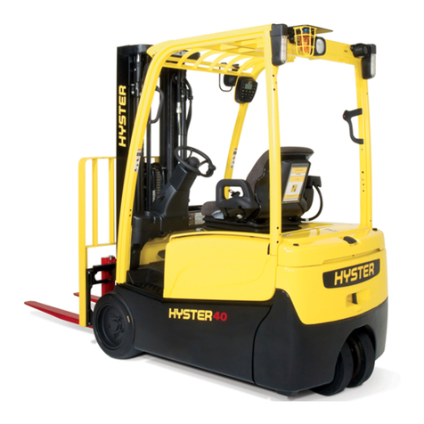
Hyster R005 (H80FT, H90FT, H100FT, H110FT, H120FT)
Forklift Service Repair Manual
DRIVE AXLE AND
DIFFERENTIAL
ASSEMBLY REPAIR
(WET BRAKE - NMHG)
S4.0, 4.5, 5.5FT, S5.5FTS (S80, 100, 120FT;
S80, 100FTBCS; S120FTS; S120FTPRS)
[H004, J004];
H4.0FT5/FT6; H4.5FTS5, H4.5FT6; H5.0-5.5FT
(H80, 90, 100, 110, 120FT) [R005, S005, U005]
PART NO. 4053147 1400 SRM 1582
SAFETY PRECAUTIONS
MAINTENANCE AND REPAIR
• The Service Manuals are updated on a regular basis, but may not reflect recent design changes to the
product. Updated technical service information may be available from your local authorized Hyster®
dealer. Service Manuals provide general guidelines for maintenance and service and are intended for
use by trained and experienced technicians. Failure to properly maintain equipment or to follow in-
structions contained in the Service Manual could result in damage to the products, personal injury,
property damage or death.
• When lifting parts or assemblies, make sure all slings, chains, or cables are correctly fastened, and
that the load being lifted is balanced. Make sure the crane, cables, and chains have the capacity to
support the weight of the load.
• Do not lift heavy parts by hand, use a lifting mechanism.
• Wear safety glasses.
• DISCONNECT THE BATTERY CONNECTOR before doing any maintenance or repair on electric lift
trucks. Disconnect the battery ground cable on internal combustion lift trucks.
• Always use correct blocks to prevent the unit from rolling or falling. See HOW TO PUT THE LIFT
TRUCK ON BLOCKS in the Operating Manual or the Periodic Maintenance section.
• Keep the unit clean and the working area clean and orderly.
• Use the correct tools for the job.
• Keep the tools clean and in good condition.
•Always use HYSTER APPROVED parts when making repairs. Replacement parts must meet or ex-
ceed the specifications of the original equipment manufacturer.
• Make sure all nuts, bolts, snap rings, and other fastening devices are removed before using force to
remove parts.
• Always fasten a DO NOT OPERATE tag to the controls of the unit when making repairs, or if the unit
needs repairs.
•Be sure to follow the WARNING and CAUTION notes in the instructions.
• Gasoline, Liquid Petroleum Gas (LPG), Compressed Natural Gas (CNG), and Diesel fuel are flamma-
ble. Be sure to follow the necessary safety precautions when handling these fuels and when working
on these fuel systems.
• Batteries generate flammable gas when they are being charged. Keep fire and sparks away from the
area. Make sure the area is well ventilated.
NOTE: The following symbols and words indicate safety information in this
manual:
WARNING
Indicates a hazardous situation which, if not avoided, could result in death
or serious injury.
CAUTION
Indicates a hazardous situation which, if not avoided, could result in minor
or moderate injury and property damage.
On the lift truck, the WARNING symbol and word are on orange back-
ground. The CAUTION symbol and word are on yellow background.
©2015 HYSTER COMPANY
TABLE OF CONTENTS
General .....................................................................................................................................................................1
Identification Plate ............................................................................................................................................. 1
Drive Axle Removal .................................................................................................................................................1
Reduction Gear Assembly .......................................................................................................................................5
Remove ................................................................................................................................................................ 5
Disassemble .........................................................................................................................................................9
Clean and Inspect ............................................................................................................................................. 13
Assemble ............................................................................................................................................................13
Install .................................................................................................................................................................20
Wet Disc Brake Repair ..........................................................................................................................................21
General .............................................................................................................................................................. 21
Remove .............................................................................................................................................................. 21
Clean and Inspect ............................................................................................................................................. 26
Install .................................................................................................................................................................27
Initial Steps For Install ................................................................................................................................27
Shimming Brake Disc Pack ..........................................................................................................................31
Final Steps For Install ................................................................................................................................. 34
Piston Housing ...................................................................................................................................................... 36
Remove .............................................................................................................................................................. 36
Disassemble .......................................................................................................................................................37
Clean and Inspect ............................................................................................................................................. 38
Assemble ............................................................................................................................................................38
Install .................................................................................................................................................................38
Parking Brake Control Lever ............................................................................................................................... 39
Remove .............................................................................................................................................................. 39
Clean and Inspect ............................................................................................................................................. 40
Install .................................................................................................................................................................40
Differential Repair ................................................................................................................................................ 42
Initial Removal Steps for Differential Housing and drive axle trumpet arm (right side) ............................ 42
Input Pinion Carrier ......................................................................................................................................... 42
Remove .............................................................................................................................................................. 42
Disassemble .......................................................................................................................................................43
Clean and Inspect ............................................................................................................................................. 44
Assemble ............................................................................................................................................................44
Preload Pinion Bearings ...................................................................................................................................45
Differential Housing and Drive Axle Trumpet Arm (Right Side) .................................................................. 46
Remove .............................................................................................................................................................. 47
Disassemble .......................................................................................................................................................47
Clean and Inspect ............................................................................................................................................. 48
Assemble ............................................................................................................................................................48
Install .................................................................................................................................................................49
Ring Gear Backlash .......................................................................................................................................... 50
Final Installation Steps for Differential Housing and drive axle trumpet arm (right side) .........................51
Pinion and Motor Carrier ................................................................................................................................. 51
Install .................................................................................................................................................................51
Drive Axle Installation ..........................................................................................................................................55
Special Tools ......................................................................................................................................................59
Torque specifications .............................................................................................................................................59
Table of Contents
i
This section is for the following models:
S4.0, 4.5, 5.5FT, S5.5FTS (S80, 100, 120FT; S80, 100FTBCS; S120FTS;
S120FTPRS) [H004, J004];
H4.0FT5/FT6; H4.5FTS5, H4.5FT6; H5.0-5.5FT (H80, 90, 100, 110, 120FT)
[R005, S005, U005]
Table of Contents
ii
Thanks very much for your reading,
Want to get more information,
Please click here, Then get the complete
manual
NOTE:
If there is no response to click on the link above,
please download the PDF document first, and then
click on it.
Have any questions please write to me:
admin@servicemanualperfect.com
General
This manual covers the repair of the drive axle,
differential, and wet disc brakes.
IDENTIFICATION PLATE
See Figure 1.
1. IDENTIFICATION PLATE
Figure 1. Identification Plate
Drive Axle Removal
WARNING
When putting the lift truck on blocks, make sure
the surface is solid, even, and level. Any blocks
used to support the lift truck must be solid, one-
piece units.
1. Put blocks on each side (front and back) of
steering tires to prevent movement of lift truck.
2. Raise lift truck and put blocks under frame so
that drive wheels do not touch floor. Put blocks
under counterweight for stability.
3. Remove mast assembly as described in section
Mast Repairs (S/N A513, A514, A613, A614,
A702, A703, A704, A705, A706, A707, A751,
A752, B513, B514, B586, B587, B588, B589,
B590, B591, B749, B750, B751, B752, B753,
B754) 4000SRM1250.
WARNING
On lift trucks with pneumatic tires, completely re-
move air from tires before removing them from lift
truck. Air pressure in tires can cause tire and rim
parts to explode, which can cause serious injury
or death. Never loosen nuts that hold together in-
ner and outer wheel halves when there is air pres-
sure in tire.
4. Remove wheels.
5. Remove fill plugs on both sides of drive axle.
See Figure 2 for lift truck models
• S4.0, 4.5, 5.5FT, S5.5FTS (S80, 100,
120FT; S80, 100FTBCS; S120FTS;
S120FTPRS) (H004, J004)
See Figure 3 for lift truck models
• H4.0FT5/FT6; H4.5FTS5, H4.5FT6,
H5.0-5.5FT (H80, 90, 100, 110, 120FT)
(R005, S005, U005)
6. Remove the drive axle trumpet arm (right side)
fill/level plug.
See Figure 2 for lift truck models
• S4.0, 4.5, 5.5FT, S5.5FTS (S80, 100,
120FT; S80, 100FTBCS; S120FTS;
S120FTPRS) (H004, J004)
1400 SRM 1582 General
1
See Figure 3 for lift truck models
• H4.0FT5/FT6; H4.5FTS5, H4.5FT6,
H5.0-5.5FT (H80, 90, 100, 110, 120FT)
(R005, S005, U005)
7. Remove the drain plugs to drain the oil into a
suitable container.
See Figure 2 for lift truck models
• S4.0, 4.5, 5.5FT, S5.5FTS (S80, 100,
120FT; S80, 100FTBCS; S120FTS;
S120FTPRS) (H004, J004)
See Figure 3 for lift truck models
• H4.0FT5/FT6; H4.5FTS5, H4.5FT6,
H5.0-5.5FT (H80, 90, 100, 110, 120FT)
(R005, S005, U005)
8. Remove the parking brake cable. Refer to the
section Wet Brakes - NMHG 1800SRM1597.
A. TOP VIEW SHOWN B. BOTTOM VIEW SHOWN
1. SERVICE BRAKE PORT
2. FILL PLUG
3. OIL BREATHER
4. FILL/LEVEL PLUG
5. BRAKE BLEEDER VALVE
6. DRAIN PLUG
Figure 2. Drive Axle Drain and Fill/Level Plugs for Lift Truck Models S4.0, 4.5, 5.5FT, S5.5FTS, (S80, 100,
120FT; S80, 100FTBCS; S120FTS; S120FTPRS) (H004, J004)
Drive Axle Removal 1400 SRM 1582
2
A. TOP VIEW SHOWN B. BOTTOM VIEW SHOWN
1. SERVICE BRAKE PORT
2. FILL PLUG
3. OIL BREATHER
4. FILL/LEVEL PLUG
5. BRAKE BLEEDER VALVE
6. DRAIN PLUG
Figure 3. Drive Axle Drain and Fill/Level Plugs for Lift Truck Models H4.0FT5/FT6; H4.5FTS5, H4.5FT6,
H5.0-5.5FT (H80, 90, 100, 110, 120FT) (R005, S005, U005)
1400 SRM 1582 Drive Axle Removal
3
9. Disconnect the brake line from the piston
chamber and drain oil into a suitable container.
See Figure 4.
1. BRAKE LINE
Figure 4. Brake Line and Piston Chamber
10. Place blocks under the axle assembly and con-
nect slings and lifting device.
11. Place blocks under the transmission to support
the transmission while removing the drive axle.
12. Remove the capscrews holding the drive shaft
and remove the drive shaft.
13. Remove the transmission isolator mounting
bolt located on top of the assembly. See Fig-
ure 5.
14. Remove the four mounting capscrews and
washers from the drive axle. See Figure 6.
15. Remove blocks and lower the drive axle assem-
bly. Pull axle forward and away from frame.
16. Place blocks under the differential assembly.
NOTE: DRIVE AXLE FOR H4.0FT5/FT6; H4.5FTS5,
H4.5FT6, H5.0-5.5FT (H80, 90, 100, 110, 120FT)
(R005, S005, U005) SHOWN. TRANSMISSION
MOUNTING FOR S4.0, 4.5, 5.5FT, S5.5FTS (S80,
100, 120FT; S80, 100FTBCS; S120FTS;
S120FTPRS) (H004, J004) IS SIMILAR.
1. ISOLATORS
2. WASHER
3. WASHER
4. CAPSCREW
5. TRANSMISSION
6. DRIVE AXLE
Figure 5. Transmission to Differential Mounting
Bolt
Drive Axle Removal 1400 SRM 1582
4