EKKO EK18RR User manual

SPECIFICATION
Scissor Reach Electric Truck
EK18RR & EK18RRL
20200905V01

Introduction
In order to meet the needs of the national en ironmental protection request,To
reduce industrial pollution and impro e producti ity,we de elop new series of
EK18RR & EK18RRL Type Scissor Reach Electric Truck . on the basis of
absorption of the ad antages of domestic & o erseas battery truck,they are
especially suitable for cargo loading and unloading, handling, stacking, etc for
food, bank, light textile, station, port, logistics and other enterprises.
The Scissor Reach Electric Truck ad anced structures such as EPS steering
system, new AC controller. It is equipped with high-quality motor, traction
battery and high-power pumping station motor. Therefore, it has the
characteristics of superior performance, con enient operation, wide field of iew,
flexible steering, reliable braking, good power, low noise, no pollution, and
beautiful appearance.
This manual describes the technical parameters of the Scissor Reach Electric
Truck, working principle and operation, maintenance, and other aspects.It can
help operators use the truck more reasonable, make its maximum effect.
It is hoped that Operator strictly abide the regulations and the precautions in this
manual when using the truck .Carefully use them so that your truck can be in the
best working condition for long period of time to maximize it’s effecti eness. And
create better economic benefits.

The Statement
Our company production model EK18RR & EK18RRL Type Scissor Reach Electric
Truck is a special motor ehicle used in factory ,tourist attractions ,amusement
places which is specified by “special equipment safety super ision regulations” .

Contents
1.The General Introduction..................................................................................... 1
2.Proper usage............................................................................................................2
3.Introduction o the product..................................................................................4
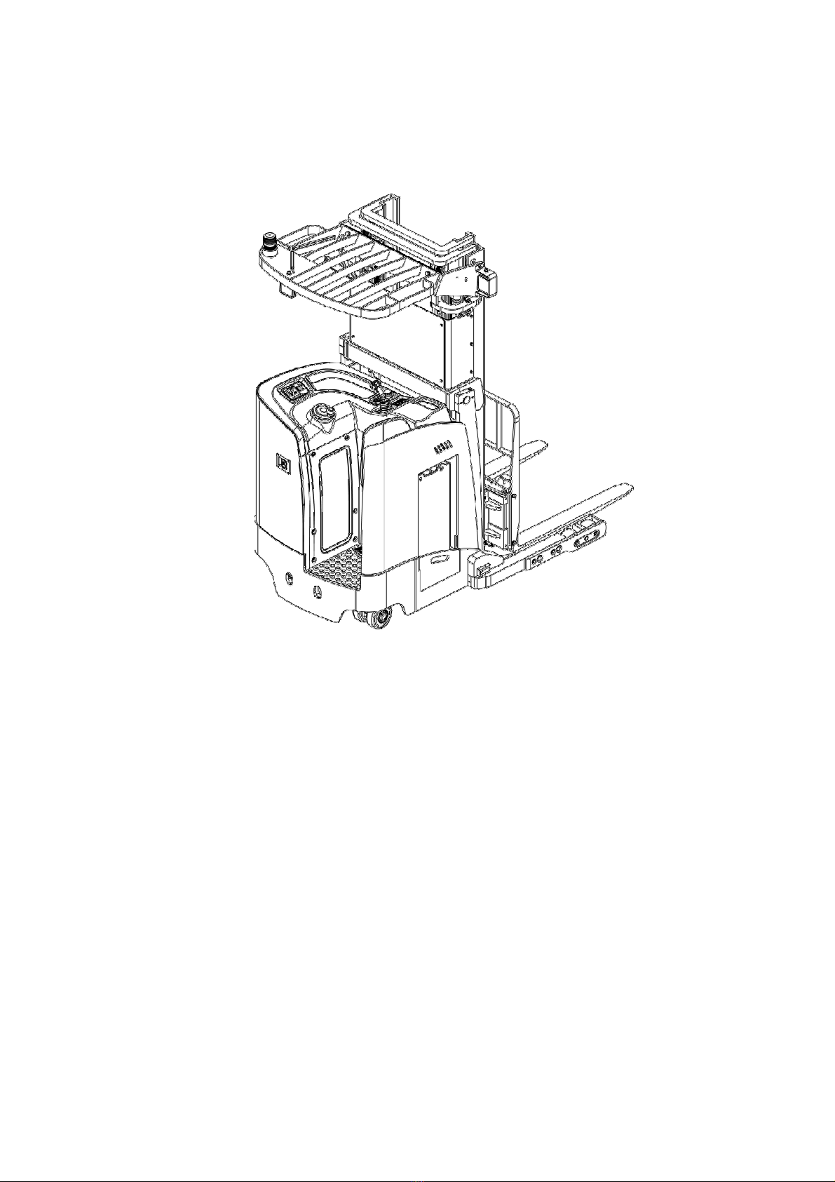
3.1Model O er iew...................................................................................................4
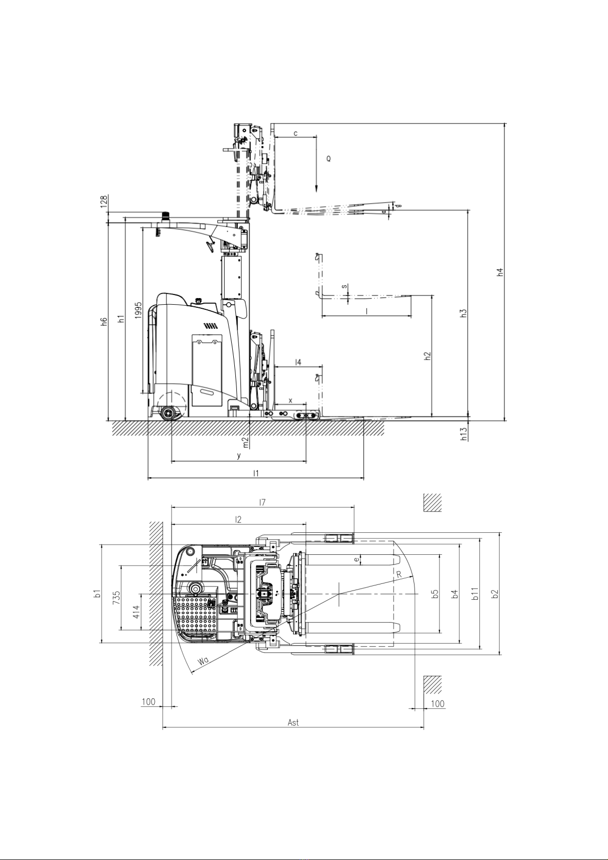
3.2Model parameters..............................................................................................5
3.3Safe operation and warning labels.....................................................................8
3.4Name plate ......................................................................................................... 8
4.Sa ety Caution..........................................................................................................9
5.Test run,Transportation,Outage....................................................................... 10
5.1Test run ............................................................................................................ 10
5.2Lifting & Transportation...................................................................................10
5.3Outage................................................................................................................ 11
6.Routine Inspection............................................................................................... 11
7.The Schematic diagram o Operating Mechanism......................................... 13
7.1Schematic diagram................................................................................................13
8Operating speci ication........................................................................................14
8.1Parking............................................................................................................... 14
8.2Loading capacity graph.....................................................................................14
8.3Lifting up............................................................................................................ 15
8.4Lowering down ................................................................................................15
8.5Fork mo e forward /backward/Left/Right .................................................. 15
8.6Fork Tilt forward /back ward ........................................................................ 15
8.7Tra eling ........................................................................................................ 16
8.8Steering ............................................................................................................ 17
8.9Braking ............................................................................................................. 18
8.10Brake structure &Brake Schematic............................................................... 18
8.11Trouble.............................................................................................................18
8.12Emergency situations..................................................................................... 19

8.13Monitor............................................................................................................ 19
9Changing and Replacement or battery............................................................ 20
9.1Replacement .................................................................................................... 20
9.2Battery display...................................................................................................21
10.Maintain Introduction.......................................................................................22
10.1Maintenance list..............................................................................................23
10.2Lubrication point.............................................................................................24
10.3Check and refill hydraulic oil......................................................................... 24
10.4Check the electrical fuse................................................................................. 25
10.5 Remo e and reinstall the shield....................................................................25
11.Trouble shooting ..............................................................................................26
12.A ter-sales service............................................................................................. 27
13.Electrical Schematic diagram.............................................................................. 28
13.1 Electrical Schematic diagram........................................................................ 28
14.Hydraulic Schematic diagram......................................................................... 29
14.1Hydraulic Schematic diagram........................................................................ 29

1
1.The General Introduction
EK18RR & EK18RRL Type Scissor Reach Electric Truck uses a battery as the
power source and AC motor as power to dri e the truck through gear
transmission,The lifting of the fork is dri en by the AC motor hydraulic dri e to
push the cylinder to lift and lower the cargo,Mo e the cargo forward &
Backward .Tilt the cargo forward & backward.As the truck Electric motor for
Lifting and Dri ing .Then it has the characteristics of labor sa ing, high efficiency,
stable cargo operation, simple operation, safety and reliability, low noise and no
pollution.
The biggest ad antage of the Scissor Reach Electric truck is that it can
not only realize the lifting.Lowering and handling of goods, but also can dri e the
goods to mo e forward and backward through the front and back expansion and
contraction of the scissor when stacking goods. In this way, the "incon enience"
caused by the "straddle legs" of the plug-in stacker is o ercome, and compared
with the same type of counterbalanced forklift, it has the characteristics of small

2
size and more flexible operation, and is especially suitable for working in narrow
passages.
The ser ice en ironment:
a.Altitude does not exceed 3937ft;
b. Indoor room temperature at +5℃to +40℃ ;
c.When en ironment temperature at +40℃,the relati e humidity can’t o er
50%,at low temperature ,allow bigger relati e humidity
d.Firm,Flat ground 。
e.It is forbidden to use this car in corrosi e en ironment such as flammable
and explosi e or acid base
2. Proper use
Please using the Scissor Reach Electric Truck according to this specification.
This is a stand on type Scissor Reach Electric Truck With solenoid al e to
control truck lifting & lowering,Mo e forward and backward,Tilt forward and
backward, and side shift
Improper use can cause personal injury or machine damage.Operators or
operating companies need to ensure proper using,
The Truck needs to be used on a firm ,flat ,intact surface and suitable
surface ,The truck is designed for indoor use at room temperature from+5°C to
+40°C
Use under light load without using permanent barriers or pits ,It is
forbidden to operate on the slops .During Operation ,The goods must be placed
approximately at the center of the truck’s load center
Lifting or Carrying people is strictly prohibited ,If carried goods .The goods
must fall on the lifting point 。
It is prohibited to use this truck on lifting or loading ramps.
The rated capacity is marked on the capacity label or nameplate.And the
operator must pay attention to the warming signs and safety instructions.
Operating lighting must be at lest 50LUX

3
Modification
Any modification that may affect the truck rated capacity,stability,or safety
operations must be appro ed in ad ance by the Truck’s original manufacturer or
Its authorized Manufacturer or its successor.This includes the effects of changes
such as Braking ,steering ,Visibility,and the addition of remo able accessories.
After the manufacturer or its successor appro es the modification or change ,The
capacity name plate ,Label,identification marks,operation and maintenance
manual must be changed accordingly
Truck damage caused by not ollowing Instruction will lose its warranty.

4
3.Introduce o the product
3.1Overview o main components
Figure 1 main components
Table 1 main components
1.O erhead guard 2.Joystick 3.Steering wheel assembly
4.Foot switch 5.Main frame assembly 6.Battery
7.Fork carriage assembly 8.Fork 9.Door frame assembly

5
3.2Truck schematic diagrame & Model parameters
Figure 2 Schematic diagram

6
Table 2The main technical parameters of the standard ersion.
Characteristics
1.2 Model EK18RR EK18RRL
1.3 Dri e type Electric Electric
1.4 Type of operation Stand on Stand on
1.5 Rated load capacity Q (t) 3960 3960
1.6 Load centre c (mm) 19.7 19.7
1.8 Axle centre to fork face x (mm) 14.65 14.76
1.9 Wheel base y (mm) 63.62 63.7
Weights 2.1 Ser ice weight with battery kg 9330 8074
Wheels/Tyres
3.1 Tire material PU PU
3.2 Dri ing wheel size
Φ×
w(mm) Φ13.5×5.2 Φ13.5×5.2
3.3 Bearing wheel size
Φ×
w(mm) Φ4.9×3.2 Φ4.9×3.2
3.4 Balance wheel size
Φ×
w(mm) 1x,2/4 1x,2/4
3.5 No of Dri ing wheel,Balance
wheel/Bearing
wheel(X=Dri ing
wheel
28.9 28.9
3.6 Track width b10 (mm) 49.6 49.6
3.7 Track width b11 (mm) 2/4 2/4
Dimensions
4.1 Mast/Fork carriage
tilt ,Forward/back ward
α
/
β
(
°
)123.27 96.42
4.2 Lowered mast height h1 (mm) 79.92 53.15
4.3 Free lift h2 (mm) 275.59 196.85
4.4 Lifting height h3 (mm) 318.9 240.94
4.5 Extended mast height h4 (mm) 93.94 93.94
4.7 Height of o erhead
guard(cabin) h6 (mm) 1.97 1.97
4.15 Lowered fork height h13 (mm) 102.28 102.28
4.19 O erall length l1 (mm) 60.16 60.16
4.20 Body Length l2 (mm) 54.72/44.1 54.72/44.1
4.21 O erall width b1/ b2 (mm) 1.58/4.72/45.3 1.58/4.72/45.3
4.22 Fork Size s/e/l (mm) 35.04 35.04
4.25 outside fork width b5 (mm) 44.49 44.49
4.26 Spoke/load surface spacing b4 22.44 22.44
4.28 Reach distance l4(mm) 1.81 1.81
4.32 Min.Ground clearance m2 (mm) 116.93 116.93
4.33 Aisle width for pallets
1000*1200 crossways Ast (mm) 118.9 118.9
4.34 Aisle width with pallet 800 x
1200 along forks Ast (mm) 75 75
4.35 Min.Turning radius Wa (mm) 81.65 81.65

7
4.37 Spoke length l7 9/9.5 9/9.5
Performance
5.1 Tra el speed,laden/unladen (km/h) 190/230 190/230
5.2 Lifting speed, with/without
load
(mm/s) 300/290 300/290
5.3 Lowering speed, with/without
load
(mm/s) 100/110 100/110
5.4 Reach speed, with/without
load
(mm/s) 6/10 6/10
5.8 Maximum climbing ability,
with/without
load
(%) Electromagnetic Electromagnetic
5.10 Brake Type 6 6
Dri e
6.1 Dri e Motor (kW) 11 11
6.2 Lift Motor (kW) no no
6.4 Battery oltage/rated capacity (V/Ah) 48/420 48/420
6.5 Battery weight (± 5%) (kg) 1585 1585
Others 8.1 Type of dri e control AC AC
8.4 Noise le el at operator‘s ear (dB(A)) ≤75 ≤75

8
3.3Sa e operation and warning labels
A.Refueling sign
B.Nameplate
C. warning label
D.Load capacity Sign
E.our kinds of misoperations are prohibited
F.It is forbidden to stand on /off the fork
G.Load capacity chart
H.Hook sticker
I.Warning be careful to pinch your hands
3.4Nameplate
Figue4 Nameplate
Figure 3 label diagram

9
4.Sa ety Caution
Please don’t
• When travel outdoor,The stacking operation makes the li ting height o
the cargo higher than the li ting point
• Place the oot or hand under or into the li ting mechanism
• Allow Non-Operators to stand in ront o or behind the truck durning
moving or li ting / lowering
• Overload
• Put your oot on the ront o the wheel may cause injury
• Li ting person, person may all and cause serious injury
• Push and pull cargo
• Use the car on the slope
• Use the car without Shielding panel
• Side load or tail load ,The cargo must be evenly distributed on the ork
• Use this car to load unstable ,unbalanced cargo
• Use this car without the manu acturer’s written consent
•The upli ted cargo will become unstable because o wind .Don’t li t the
cargo in windy condition
Obser ing different ground condition during dri ing .The cargo may fall down or
the car may lose control ,Please check the loading situation frequently,If the cargo
becomes unstable .Stop the operation of the truck immediately . When the cargo slide or
slide off the truck,Stop the car by pressing emergency stop switch .Please refer to
Chapter 6 for any truck Trouble .Maintain according to regular inspection.The forklift is
not waterproof,Please use it in dry en ironment.Continuous operation for a long time
may damage the power box ,please stop operating when Hydraulic oil temperature is
too high .
• The operator should put on sa ety shoes when operating the orkli t
• The car is suitable or indoor use in temperature rom +5°C to 40°C
• Operating lighting must be at least 50LUX
• Don’t use the car on the slope
!
!

10
• In order to prevent sudden movement o the car when the car is not
operated (such as caused by others),turn o the car power and remove the
key when not operating
5.Test run,Transportation,Outage
5.1Test run
Table 3 test data
Model EK18RR & EK18RRL
Packing weight(LBS)About 8074
Lifting height(Inch)196.85
Size(Inch)106.3*104.33*59.06
After recei ing our new forklift or when it needs to be retest please with process
with following steps before (the first )operation of the forklift :
• Check if all parts are included .and there is no damage
• Battery installation and charging (refer to Chapter 9)
• Carry out daily inspection and machine function inspection
5.2Li ting & Transportation
Remo e the cargo during transportation ,Lowered the
fork to the lowest position And according to Figure 5 Safety
fixed the car with special lifting equipment
Li ting
Use Special Crane and li ting equipment
Don’t stand under shaking cargo
Don’t enter the dangerous area when rising
Parking the truck safely,and And fasten the car body as fig 5 shows
Lifting the truck to the destination ,Before Mo ing lifting equipment please safety
Fixed the car ,
!Fig 5 Lifting Point

11
The rope point can referred to figure 6
Transportation
The Truck should be irmly ixed on the truck during transportation
Lowered fork and parking the truck safety
As figure 6 shows Use the special binding belt to
fix the tow big ribs of the car .And fixed other
side on the carrier
5.3Outage
When Storage remo e the cargo and lowered the fork to lowest
position.Grease all lubrication points mentioned in this manual (check
regularly)to pre ent rust and dust. Remo e the battery and check the truck to
ensure no extrusion during storage.
When the car finally out of ser ice ,send the car to designated recycling
company .According to regulations ,Oil,Batteries and electronic components
must be recycled .
6.Routine Inspection
This Chapter Describes check the car before using
Routine inspection can effecti ely find out the defect or error of this car,The
following points should be checked before operation.
Remove the cargo ,Lowered the ork.Please don’t use the car i there is any
Problem.
• Check for scratches ,Deformation .or Cracks
• Check if the cylinder leaks of oil
• check running condition of the car
• Check if the chain or roller damage or corrosion
Fig6 Fixed Point

12
• Check if the wheels can mo e smoothly
• Press the emergency stop button to check the emergency brake function
• Check the lift function, tilt function and Reach function of the forklift
• Check the Buzzer
• Check whether the display is displayed normally
• Check that all bolts and nuts are tightened
• Check the function of Key switch
• Check the speed limit switch
• Visually Check for any damaged tube or wires
• If the car with Protecti e barrier .Check for damage and correct installation.

13
7.The Schematic diagram o Operating Mechanism
7.1 Schematic diagram
Fig 7 Operating console Fig 8 Schematic diagram of the joystick
7.1 Schematic diagram of Dri ing and Lifting & lowering
Fig 10.1 Dri ing diagram Fig10.2 Lifting& Lowering diagram
Fig
9
Key
Switch

14
8.Operating speci ication
Please ollow the warning and sa ety instructions be ore operating the car
(see as chapter 4)
Please Ensure that cargo or other equipment will not lead to poor visibility
be ore operating the car
Ensure cargo le el and stable placed .And conduct daily inspection .Insert
the key into the key Switch(Figure 9),Turn the key clockwise to “ON”
position. Press the horn button(as figure8.8) to start the buzzer,Before
finally inserting the key switch,The emergency stop switch(Fig 7.3) must be
carefully pulled up.
8.1Parking
Pls Don’t Park on the ramp
Mo e the joystick (Figure 10.1) to the middle position or release the foot switch
(Figure 7.6) to truck parking brake while dri ing. The ehicle is equipped with a
parking brake.
Always lower the forks completely and dri e the truck to a safe area. Turn the
key counterclockwise to the "off" position and pull out the key.
8.2Loading capacity Graph
The loading capacity Graph shows a gi en load center c [Inch] and a car with
horizontal load ,the maximum load capacity Q [lbs]In the corresponding lifting
height of the truck H [lbs],The white markings on the Door frame indicate the
range of lift that can be achie ed.For example, a cargo's center of gra ity distance
c is 19.69Inch, the maximum lifting height H is 196.85Inch, and the maximum
load capacity Q is 1100lbs.
Fig11 Loading capacity chart
!
!

15
8.3Li ting up
Pls don’t overload,The related capacity is 1800KG .Only increase the load
capacity allowed by the load capacity graph
Pull the joystick in the B direction (Figure 10.2) to realize the lifting of the cargo.
Extend the fork to the bottom of the cargo, and then raise the fork to a suitable
height. Retract the fork without touching the fork and the cargo with the straddle
legs. Only when the fork is retracted then you can continue to lift the cargo to the
desired height height. This operation needs to be performed with the foot switch
(Figure 7.6) depressed.
8.4Li ting down
If the fork is on the shelf ,carefully Mo e the car with the pallet rack or mo e the
car off the shelf separately ,Then Operate the joystick carefully, lower the cargo
in the F direction (Figure 10.2) until the forks lea e the pallet rack, and then
carefully dri e the truck away from the cargo. This operation needs to be
performed with the foot switch (Figure 7.6) depressed.
8.5Fork move orward /backward/Le t/Right
After stepping on the foot switch (Figure 7.6), press the button (Figure 8.1) to
mo e the fork forward.
After stepping on the foot switch (Figure 7.6), press the button (Figure 8.2), and
the fork mo es backward.
After stepping on the foot switch (Figure 7.6), press the button (Figure 8.5), and
the fork mo es to the right.
After stepping on the foot switch (Figure 7.6), press the button (Figure 8.6), and
the fork mo es to the left.
8.6Fork Tilt orward /back ward
After stepping on the foot switch (figure 7.6), press the button (figure 8.3) to tilt
the fork forward.
!
This manual suits for next models
1
Table of contents
Other EKKO Forklift manuals

EKKO
EKKO EK07S Series User manual

EKKO
EKKO EB13E User manual

EKKO
EKKO EP20LI Series User manual

EKKO
EKKO EK20LI Series User manual

EKKO
EKKO EPE20LI Series User manual

EKKO
EKKO EK18RF User manual

EKKO
EKKO EK25SLP User manual

EKKO
EKKO EK15A-189LI Series User manual

EKKO
EKKO EB20E User manual

EKKO
EKKO EK13A User manual
Popular Forklift manuals by other brands

OTTO MOTORS
OTTO MOTORS Lifter MkIV Operation and maintenance manual

Noblelift
Noblelift OPX15 instruction manual

Meijer
Meijer KOOI-REACHFORKS RE2 Instructions and parts manual

Hyster
Hyster A244 Service & repair manual

Noblelift
Noblelift FE4P16-35 N Series Operation and maintenance manual

CESAB
CESAB S210 Repair manual