Gima D 351 User manual

D 351
IMPULSE HEAT-SEALER
v.1.5

Impulse sealer GIMA D 351
I
WARNING
BEFORE USING THE MACHINE, READ CAREFULLY THIS MANUAL FOR A CORRECT USE IN
ACCORDANCE WITH THE SAFE RULES.
CONTENTS
I SAFETY RULES page 1
II EXPECTED USE page 1
III CHARACTERISTICS page 2
IV MACHINE INSTALLATION page 2
V LIST OF THE EXTERNAL PARTS page 3
VI INSTRUCTIONS FOR USE page 4
VII MAINTENANCE page 7
VIII LIST OF THE INTERNAL PARTS page 12
IX ELECTRICAL DIAGRAMS 230 Vac page 13
X LIST OF THE SPARE PARTS FOR
THE NORMAL MAINTENANCE page 14
XI LIST OF THE SPARE PARTS FOR
THE EXTRAORDINARY MAINTENANCE page 14
XII PROBLEMS & SOLUTIONS page 16
XIII WARRANTY TERMS page 17
XIV SPARE PARTS ORDERING page 17
XV HOW TO DISCARD THE MACHINE page 17
CE DECLARATION OF CONFORMITY
SYMBOLS:
warning meaning danger
warning meaning particular suggestion
warning meaning suggested maintenance

Impulse sealer GIMA D 351
1
I. SAFETY RULES
In this manual we give you all the instructions for a correct use of the machine and for its maintenance.
• This is the reason why the operator must be properly trained and have full knowledge of the contents of this manual.
• If the operator can not read it, the responsible has to do the necessary, also the translation into the known language.
• The machine can be used only for the employ for which has been created.
• The machine has to be used by properly trained operators.
• The heat-sealer must be used only indoor and in a dampness free environment.
• Before opening the machine, unplug it from the main power supply.
• Never introduce in the sealing area anything except the bag to be sealed.
• Do not introduce in any opening of the heat-sealer machine metallic objects, to avoid electrical shocks.
• To guarantee a constant and regular functioning of the machine, it is important to keep clean the machine.
• Do not clean the heat-sealer with fluid or spray cleaners. Clean only by a slightly moist cloth.
• Use only original spare parts.
• It is advisable to have the heat-sealing machine checked by a qualified technician every year.
• In case of repair or checking, we can modify the machine to improve its functioning and development.
GIMA s.p.a. is not responsible for direct and indirect damages derived from an incorrect use of the heat-sealer.
II. EXPECTED USE
The GIMA D 351 is an electrical impulse sealing machine for closing sterilization bags as per DIN 58953 P. 7
rules.
IT HAS NOT TO BE USED FOR ANY DIFFERENT EMPLOY

Impulse sealer GIMA D 351
2
III. CHARACTERISTICS
• Sealable materials: paper/polypropilene/polyesther-tyvek/polyesther-polyethilene
• sealing rules DIN 58953 P. 7 rules
• Sealing length: mm. 350
• sealing width: mm. 8
• Electronic control of the sealing time from 0÷5 sec.
• Incorporated cutting device.
• Power supply: 230V - 50/60 Hz mono-phase
• Max. absorption 900 W only during the sealing.
• Dimensions:
width mm. 439
height mm. 175
dept mm. 311
• Weight: Kg. 18
• CONSTRUCTION AS PER CEI EN 60204-1 RULES
IV. INSTALLATION
• Use the machine only indoor, in dampness and moistness free environment.
• Set it on an enough solid table
• Only after checking that the luminous switch (n. 2 pict 2) is in “O” position, link the machine, through the
cable (n° 1 pict. 1), into a earthed power source with the same voltage marked on the target as the one
below.

Impulse sealer GIMA D 351
3
V. LIST OF THE EXTERNAL PARTS
pict. 1
1 : power supply cable 3 : identification data plate
2 : main switch 4 : rear cover fixing screws
5 : pivoted plain
pict 2
1 cover
2 spool rolls
3 pivoted plain cover
4 cutter knob
5 pivoted plain cover fixing screws
6 pivoted plain knob
7 upper mobile bar
8 lower sealing bar
9 command panel knob
1
2
3
9
6
4
5
3
1
8
4
7
2
5

Impulse sealer GIMA D 351
4
pict. 3
1 : adjustment opening bars ball grip 3 : lower bar adjustment screw locknuts
2 : lower fixing cover screws 4 : cutter blade
VI. INSTRUCTIONS FOR USE
THE OPERATOR HAS TO BE TRAINED AND KNOW THE CONTENTS OF THIS
MANUAL
CLOSING OF PREFORMED BAGS AFTER FILLING
• Put the luminuous switch (n. 2 pict. 1 ) in “I” position. This one will switch on and the heat sealer will be
ready for the use.
• Adjust the sealing time, through the potentiometer (n. 9 pict 2), setting the right value according to the bags to
seal (see SUGGESTED SEALING TIME).
• Introduce the mouth of the bag between the bars to let a free edge, quite mm. 20, over the seal.
• Through the pivoted plain knob (n° 6 pict. 2), exercise a little pressure on the moving bar (n° 7 pict. 2 ), the
bar will close for the set sealing time and the sealing led (n° 2 pict. 4 ) will switch on ,showing the sealing
phase.
• As the sealing led (n ° 6 pict. 4) switch off, the cooling led (n°1 pict. 4) automatically will switch on and the
bars will kept in pressure the time necessary to obtain a perfect seal.
• As this cooling led switch off, the bars will automatically open to allow to the operator to take out the bag
sealed.
2
3
2
1
4

Impulse sealer GIMA D 351
5
THE SEALING TIME HAS TO BE SET ACCORDING TO THE SPECIFICATIONS OF THE
BAG TO BE SEALED AND THE DESIRED OUTPUT.
A comparative electronic control limits the heating of the resistance to avoid any overheating in case of fast
sealing sequence.
WE SUGGEST YOU TO KEEP AN OUPUT OF 6/7 SEALS PER MINUTE.
pict. 4
1 : led cooling phase 3 : sealing time adjustment knob
2 : led sealing phase 4 : sealing phase alarm led
SUGGESTED SEALING TIME
The DN 350 S is equipped through a electronic matching system that limits the sealing wire heating during its
use to avoid high heating storing up in case of rapid sealings sequence. Than the set time about the a) case is
suitable only for the first and/or second sealing.
a) first sealing or long sealing intervals
FLAT BAGS: potentiometer knob (n° 3 pict 4) in position 8/10 (*)
BAGS WITH GUSSET: potentiometer knob (n° 3 pict 4) in position 8/10 (*)
b) sealing made in rapid sequence
FLAT BAGS: potentiometer knob (n° 3 pict 4) in position 8/10 (*)
BAGS WITH GUSSET: potentiometer knob (n° 3 pict 4) in position 8/10 (*)
(*) depending by the real supply voltage line
after the automatic re-opening of the sealing jaw, at the end of the cycle , we suggest to wait
for 4 or 5 sec. before doing the next seal, in order to get a max max output of 6/7 per
minute
4
3
2
1

Impulse sealer GIMA D 351
6
SAFETY ELECTRONIC CONTROL
In case of fault of the heating electronic control, the RED WARNING led (n° 4 pict. 4) will switch on and, in
the same time, the power supply of the resistance will be interrupted .
In this case stop the production and get in touch with your Dealer Service Department.
PRODUCTION OF POUCHES FROM THE SPOOL
• The spool can be cut both form right or left and viceversa.
Then take the cutter knob (n°4 pict 2) to one the two edges to allow the spool in-feed.
• Place the spool on the rolls (n° 2 pict. 2) and introduce the spool edge through the slit, as shown in
the pict. 5. till it will exit between the sealing bars (n° 7 and 8 pict. 2), to get the desired pouch length you
would produce.
• Through the pivoted plain knob (n° 6 pict. 2), start the sealing cycle
• While the bars are closed, during the sealing and the cooling phases, let flow on the side the cutter
knob (n° 4 pict. 2) to cut the spool.
• At the end of the cycle, the bars will open and the bag is ready to be filled.
• Repeat the in-feed operation, to prepare the next pouch
pict. 5

Impulse sealer GIMA D 351
7
VII. MAINTENANCE
IT CAN BE EFFECTUATED ONLY BY TRAINED TECHNICIANS
ALWAYS
UNPLUG THE POWER SUPPLY CABLE (n° 1 pict. 1)
1) machine opening procedure :
To access top the inner components it is needed to remove the cover (n° pict. 2) of the machine.
Do as follows :
a) extract the cutter knob (n° 4 pict. 2) in vertical direction
b) unscrew the two rear screws (n° 4 pict. 1) and the two lower screws (n° 2 pict. 3)
c) Remove the cover (n° 3 pict. 2) of the pivoted plain , after to have unscrewed its fixing
screws (n° 5 pict. 2)
PAY ATTENTION TO THE CUTTER BLADE (n° 4 pict. 3)
d) unthread in front , the cover from the machine
2) glass-PTFE protective cloth (n. 24 pict. 7)
The protective cloth could be damaged for normal use , for too long sealing time, or for the casual introduction
of any tools between the bars.
For the replacement proceed as follows:
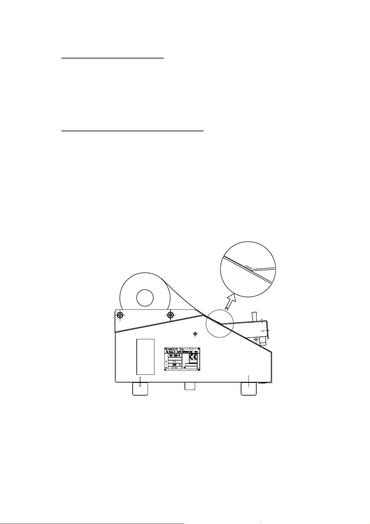
a) set the pivoted plain (n°3 pict. 6) on the max opening using the adjustment opening bars ball
grip (n°1 pict. 3) located underneath the base of the machine, loosen its locknut.
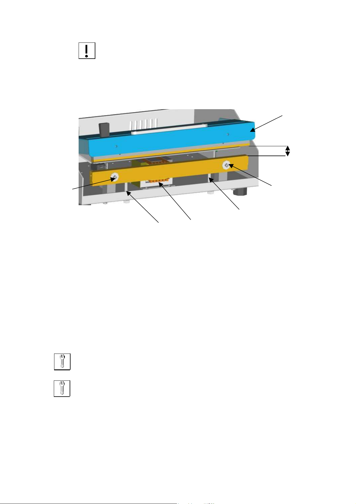
b) unscrew and remove the two screws (n° 1 pict. 6)
c) extract the lower sealing bar (n° 8 pict. 2) from the machine
To work more softly , unplug the two power supply cable (n° 30 pict. 7) from the tails of the bar.
d) replace the old cloth with a new one. The original spare clothes have adhesive bands to facilitate the
application
It is very important that the bags do not make any crumples
e) fit back the sealing bar proceeding on the contrary.
f) before tighten the two screws (n. 1 pict. 6 ), be sure that the bar perfectly leans on its own
stands (n° 2 pict. 6)

Impulse sealer GIMA D 351
8
do not loosen the two adjustement stands (n° 2 pict. 6)
g) restore the opening of the pivoted plain to its work position : act through the ball grip (n°1 pict. 3) till
to get the “h” gap = 8 mm. as shown in the picture n° 6
pict. 6
1 : lower sealing bar fixing screws 3 : pivoted plain
2 : lower sealing bar adjustment stand 4 : electromagnet
3) lower sealing bar resistance replacement
The resistance could be deformed or interrupted because of a casual introduction of chirurgical tools or any other
solid objects between the bars.
For the replacement, follow the upper instructions till the point c) removing the protective cloth too. Then :
a) unscrew the two screws (n° 28 pict 7)
b) remove the damaged resistance keeping care that you do not loose the two sockets (n° 27 pict.7) and
the two compensation springs (n° 29 pict. 7)
c) check the sub-resistance band (n° 26 pict. 7) and , if damaged, replace it.
d) Fit back all proceeding on the contrary.
the resistance must be fit well stretched during its fitting through the screws (n° 28 pict 7).
do not act the machine without the sealing wire connect to the timer board, to avoid damage to the
probe NTC located on the timer board
2
2
1
1
h
3
4

Impulse sealer GIMA D 351
9
pict. 7
12 sealing bar
13 sealing bar fixing screw
14 glass-PTFE fixing washer
24 glass-PTFE protective cloth
25 resistance
26 sub-resistance band
27 socket
28 resistance fixing screw
29 compensation spring
30 resistance supply cable
4) upper mobile bar protections replacement
The protective cloth (n° 31 fig. 8 ) and the pressure rubber (n° 32 fig. 8 ) of the upper mobile bar
(n° 16 pict. 8 or n° 7 pict. 2) could consume or damage.
For the replacement proceed as follows:
a) extract the cutter knob (n° 4 pict. 2) in vertical direction
b) remove the pivoted plain cover (n° 3 pict. 2) after unscrewing the two screws (n° 5 pict. 2)
c) remove the upper mobile bar (n° 16 pict. 8) after unscrewing the two fixing screws (n° 20 pict. 10) Check
the protective cloth and pressure rubber conditions and , if necessary, replace them
d) during the fit back, check that the upper mobile bar will be aligned and parallel with the lower sealing bar ,
before to tighten its screws.(n° 20 pict. 10)
25
14
14
24
26
13
12
29
27
28
30

Impulse sealer GIMA D 351
10
pict. 8
16 upper mobile bar 32 pression rubber
31 glass-PTFE protective cloth 33 bar fixing screw
5) cutter blade replacement :
The cutter group blade has a time-life . For the replacement proceed as follows :
TAKE MUCH CARE NOT TO HURT YOURSELVES WITH THE KNIFE
a) extract the cutter knob (n° 4 pict. 2) in vertical direction
b) remove the pivoted plain cover (n° 3 pict. 2) after unscrewing the two screws (n° 5 pict. 2)
c) Move the cursor (n. 34 pict 9) totally on the left and remove it from its place on the top (see pict. 10)
d) Remove the knife (n. 35 pict 9), loosing the fixing screws (n. 36 pict 9).
e) the blade has four sharps : check if one of them is working too. On the contrary replace the blade.
f) fit back on the contrary
pict. 9
17 knob 36 blade fixing screw
34 cursor 37 plate
35 blade 38 guide support

Impulse sealer GIMA D 351
11
6) line fuses replacement
UNPLUG THE POWER SUPPLY CABLE
(n°1 pict.1)
The 4 A protection line fuses could be interrupted , if the green light of the main switch (n° 2 pict. 1) does not light
and the machine does not work.
a) Set the main switch (n° 2 pict. 1) in position OFF (“0”).
b) extract the fuses from the fuse box ( see below) and replace them with other of the same kind and with
the same value.
pict. 10
7 pivoted plain 44 resistance supply micro switch adjustment screw
20 upper mobile bar fixing screw 45 bushing
42 electromagnet starting micro switch adjustment screw 46 elastic ring
43 electromagnet pressure adjustment screw 47 pivot

Impulse sealer GIMA D 351
12
VIII. LIST OF THE INTERNAL PARTS
pict. 11
2 main switch 50 transformer
3 electric supply socket 51 electronic timer board
4 line fuses box 52 EMQ ant jamming filter
12 lower sealing bar 53 command panel board
48 opening pivoted plain spring 54 electromagnet & resistance start micro switch
49 electromagnet 55 electronic safety board
56 adjustment opening bars ball grip

Impulse sealer GIMA D 351
13
IX. ELECTRIC DIAGRAM
line 230 Vac 50/60 Hz
AL alarm led MTC cycle starting micro switch (elettromagnet)
CP command panel MTR heating starting micro switch
EL electromagnet R strap resistance
F ant jamming filter SC electronic safety board
FC9 flat cable 9 pins TC electronic timer board
FL fuses 4 AF TR transformer 250VA , 230 / 24 Vac
F1 fuse 100 mA tri cooling time adjustment trimmer
GI main switch ts safety time trimmer

Impulse sealer GIMA D 351
14
line 115 Vac 50/60 Hz
AL alarm led MTC cycle starting micro switch (elettromagnet)
CP command panel MTR heating starting micro switch
EL electromagnet R strap resistance
F ant jamming filter SC electronic safety board
FC9 flat cable 9 pins TC electronic timer board
FL fuses 6,3 AF TR transformer 250VA , 1150 / 24 Vac
F1 fuse 100 mA tri cooling time adjustment trimmer
GI main switch ts safety time trimmer

Impulse sealer GIMA D 351
15
X. LIST OF THE SPARE PARTS FOR THE NORMAL MAINTENANCE
CODE POSITION SET
n° pieces DESCRIPTION
20010 12 pict. 7 1 complete sealing bar
20001 24-30 pict. 7 10 protec. cloth for upper & lower bar
20002 25 pict. 7 5 strap resistance
20003 26 pict. 7 3 sub-resistance band
20012 27+28 pict. 7 1 socket+screw
06032 29 pict. 7 4 compensation spring
20011 16 pict. 8 1 complete upper mobile bar
20005 32 pict. 8 3 pressure rubber
48002 35 pict. 9 1 blade
XI. LIST OF THE SPARE PARTS FOR THE EXTRAORDINARY MAINTENANCE
CODE POSITION SET
n° pieces DESCRIPTION
DB 90061 2-3-4 pict. 11 1 main switch
DB 20011 52 pict. 11 1 ant jamming filter
90029 54 pict. 11 2 starting micro switches
20015 49 pict. 11 1 Elettromagnet
20016 50 pict. 11 1 Transformer
20004 51 pict. 11 1 electronic timer board
20025 55 pict. 11 1 electronic safety board

Impulse sealer GIMA D 351
16
XII. PROBLEMS & SOLUTIONS
PROBLEM CAUSE SOLUTION
The machine does not function and the
warning light of the main switch does
not flash
-The power cable is not correctly
insert into the wall socket or in the
machine socket.
- The fuses are interrupted
- The internal electrical circuit of the
machine is interrupted
-Insert correctly the plug into the
socket
- Check and, if necessary, replace the
fuses with others of the same kind
and the same value
- Put in contact with the manufacturer
The fuses intervene every cycle The electronic circuit of the sealing
wire is in short circuit Check if the power cables of the
resistance are correctly linked
The machine functions in a
discountinuous way The power cable is interrupted Replace the power cable
The machine functions but, after a
serie of rapid seals, does not more seal
- The control electronic circuit of the
sealing temperature stopped
temporarily the machine
- The thermo protection of the
transformer intervenes
- Let the machine cool
Pressing the pivoted plain , the cycle
starts but the machine does not seal - Sealing time on “0”
- Sealing electronic circuit interrupted
- Sealing wire interrupted
-
The closing bar control micro switch
is interrupted
- Set the hand wheel as shown on
page 5
- Put in contact with the manufacturer
- Replace the resistance after checking
electrical circuit as shown on page
- Put in contact with the manufacturer
The machine does not correctly seal:
- the temperature is too low
- the temperature is too high
- The sealing time is set on a too low
value
- The sealing time is set on a too high
value
- Set the hand wheel as shown on
page 5
- Set the hand wheel as shown on
page 5
The cooling time is too short or too
long - The cooling electronic circuit is not
right set or faulty - Put in contact with the manufacturer
The seal is not perfect - The protective clothes in glass/PTF
are consumed
- The rubber of the upper mobile bar
is damaged
- The sealing wire is damaged
- Remove the sealing bar from its
place and replace what necessary
(see page 7,8 )
The sealing bar does not stay in
pressing - The electromagnet is interrupted or
disconnected
- The micro switch cycle is interrupted
- Check the electrical/mechanical links
- Put in contact with the manufacturer
alarm led is lighted on - The safe electronic circuit intervenes
because of a lack in the electronic
sealing circuit working
- The 9 pins flat cable could be not
correctly insert
- Put in contact with the manufacturer
(we suggest not to use the machine)
- Check the links to the control panel
and the board n°51 pict. 11

Impulse sealer GIMA D 351
17
XIII. WARRANTY TERMS
The GANDUS’s heat-sealer are built to perform and they are guaranteed for 12 months after delivery.
For the duration of the warranty, the manufacturer will replace parts or elements that, under his
examination, should result defective for factory construction, error or faulty materials, but not the
parts presenting normal wear, demonstrating incorrect use of the equipments or tampering.
Are excluded from this warranty the materials subject to normal wear, such as protective cloths, belts,
straps rubber, resistors, etc.
This warranty is accepted in our offices, for equipment delivered to us free of charges, that shall be returned on
ex-factory basis.
This warranty is void if the heat-sealer has been altered or has been fitted with unauthorized spare parts.
The warranty is also void if the customer does not comply with the form of payment established
even once.
For the parts not manufactured by GANDUS, the warranty is conditioned by the one provided by the supplier.
For the duration of the warranty too, if the heat-sealer is subject to any intervention by our personnel
outside our seat, the manufacturer will charge workhour and transportation fee.
XIV. SPARE PARE ORDERING
Always mention:
1. Serial number of the sealing machine
2. Quantity of the spare part you need
3. Position and table number identifying the requested spare part
XV. HOW TO DISCARD THE MACHINE
According to the DIRECTIVE 2002/96/CE rules this symbol indicates that the device,
when its work-life is ended, must not be discarded as a urban waste.
It can be given to a suitable discharging centers of the electronics and electric equipments
or delivered to the dealer if you purchase an equivalent device.
The device owner is responsible for the delivery in to the discharging centers.
To get more informations about the discharging system, we suggest you to contact your
local discharging waste service.
The right discharging of the disuse devices avoids such a negative consequences to the ambience and the human
health.
Table of contents
Other Gima Food Saver manuals