Gima D 400 User manual


GIMA D400
I
WARNING
BEFORE USING THE MACHINE, READ CAREFULLY THIS MANUAL FOR A
CORRECT USE IN ACCORDANCE WITH THE SAFE RULES.
CONTENTS
1 INTRODUCTION
1.1 Use and safekeeping of this manual page 1.1
1.2 Manufacturer’s responsability limits page 1.2
1.3 Expected use page 1.2
1.4 Technical characteristics page 1.3
1.5 Transport and moving page 1.3
1.6 Safety rules page 1.4
1.7 To discard the machine page 1.5
2 INSTRUCTIONS FOR USE
2.1 Installation page 2.1
2.2 Pouches introduction adjustment page 2.1
2.3 Electrical wiring page 2.2
2.5 Switch on the machine page 2.2
2.6 First employ page 2.3
3 COMMAND PANEL
3.1 Keys symbols page 3.1
3.2 Operative visualizations page 3.2
3.3 Operative settings page 3.2
3.4 Machine alarms page 3.3
3.5 Block - Unblock display page 3.5
4 CORRECT FUNCTIONING
4.1 Sealing temperature page 4.1
4.2 Sealing pressure page 4.1
4.3 Sealing quality page 4.1
4.4 Normal stop of the heat sealer page 4.2
4.5 Emergency stop page 4.2
4.6 Bag jamming page 4.3
4.7 Pouches expulsion page 4.5
5 MAINTENANCE
5.1 Opening the machine page 5.1
5.2 Main previous maintenance rules page 5.1
5.3 Thermoelectrical protections page 5.3
5.4 Replacement of the probe sealing jaws page 5.3
5.5 Sealing pressure page 5.4
5.6 Replacement of the transport belts page 5.6

GIMA D400
II
5.7 Replacement of the heating element page 5.8
5.8 Replacement of the sealing jaws page 5.11
5.9 Replacement of the line fuses page 5.12
5.10 General main board page 5.12
5.11 Replacement of the motoreducer page 5.13
5.12 Infeed photocell calibration page 5.14
6 ELECTRICAL DIAGRAMS
6.1 Electrical diagram at 230 V page 6.1
6.2 Electrical diagram at 115 V page 6.2
7 WARRANTY TERMS AND SPARE PARTS
7.1 Warranty terms page 7.1
7.2 Spare parts order page 7.1
8 PROBLEMS AND SOLUTIONS
8.1 Power supply page 8.1
8.2 Sealing page 8.1
8.3 Transport page 8.2
8.4 Alarms page 8.2
9ACCESSORIES
9.1Working plane page 9.1
CE DECLARATION OF CONFORMITY
SYMBOLS:
warning meaning danger
warning meaning particular suggestion
warning meaning suggested maintenance

G I M A D 4 0 0
1.1
1. INTRODUCTION
1.1 Use and safekeeping of this manual
We thank you for the trust you put in us by buying our heat-sealer Gima D400.
We are sure that, following correctly the instructions in this manual, you will find the quality
of this product worth of appreciation.
For this reason, please give noted the present instructions to all people who are likely to
use this machine.
WARNING
All people involved in the operation of this heat-sealer whether their task is
production, maintenance or revision must read this instruction manual.
The instructions in this use and maintenance manual indicate, for this machine, the correct
operations as intended in its design and technical specifications.
This booklet, provided with each heat-sealer is to be considered indispensable part of the
equipment.
It must be safekept for continuos consultation for as long as the machine is
operated.
This manual must be kept always close to the heat-sealer at hand of the operator for
easy consultation.
In case of loss or damage, the customer can ask for a new manual of instructions,
mentioning:
-model
-serial number
-manufacturing date
This information are written on the identification plate (pict.1.2), situated on the rear of the
machine (pict.1.1).
The manufacturer reserves the right to improve or modify its products, without updating the
items issued previously or their manuals.

G I M A D 4 0 0
1.2
3
1
2
pict.1.1
pict.1.2 (Id. plate n.1-
pict.1.1)
1
Identification plate
2
Main power supply
3
Green general
luminous switch
1.2 Manufacturer’s responsability limits
GANDUS SALDATRICI s.r.l. socio unico is not responsible for direct or indirect damages
derived from an incorrect use of the heat-sealer, specifically:
-employing this heat-sealer for other use than the one specified in this manual
-failure in the scheduled maintenance
-modify the heat sealer without the authorisation of GANDUS Saldatrici s.r.l.
socio unico
- use of non original spare parts and not suitable for the model
- partial or total non compliance with the instructions
- exceptional events
1.3 Expected use
The Gima D400 is a continuous heat-sealer for closing hermetically sterilization pouches
with chirurgical instruments and disposables made with multilayered envelopes like
polyester / polyethylene, or other multilayered envelopes bags like paper/polyethylene,
aluminium/polyethylene, etc.
The machine has been studied to be used only by an operator.
WARNING
The machine must not be used for other use than the one above mentioned,
for which the machine has been designed and built.
WARNING
THE HEAT SEALER MUST NOT TO BE USED FOR THE SEALING OF SINGLE
PLASTICS FILMS LIKE POLYETHILENE, PLYPROPYLENE, PVC, AND SO ON.

G I M A D 4 0 0
1.3
1.4 Technical characteristics
Sealing speed 6 m/min
Electronic temperature control with 10°C - 200°C ( 1%)
Automatic stop of the heat-sealer if the sealing temperature has fallen down from
setting value in a range 5°C.
Autotest function
Check internal temperature machine using thermal probe
LC display with 2 lines for 8 characters
Membrane keyboard with keys with buzzer
Sealing width 12,5 mm multilines
Free edge over the seal 0 - 30 mm
Preadjusted sealing pressure
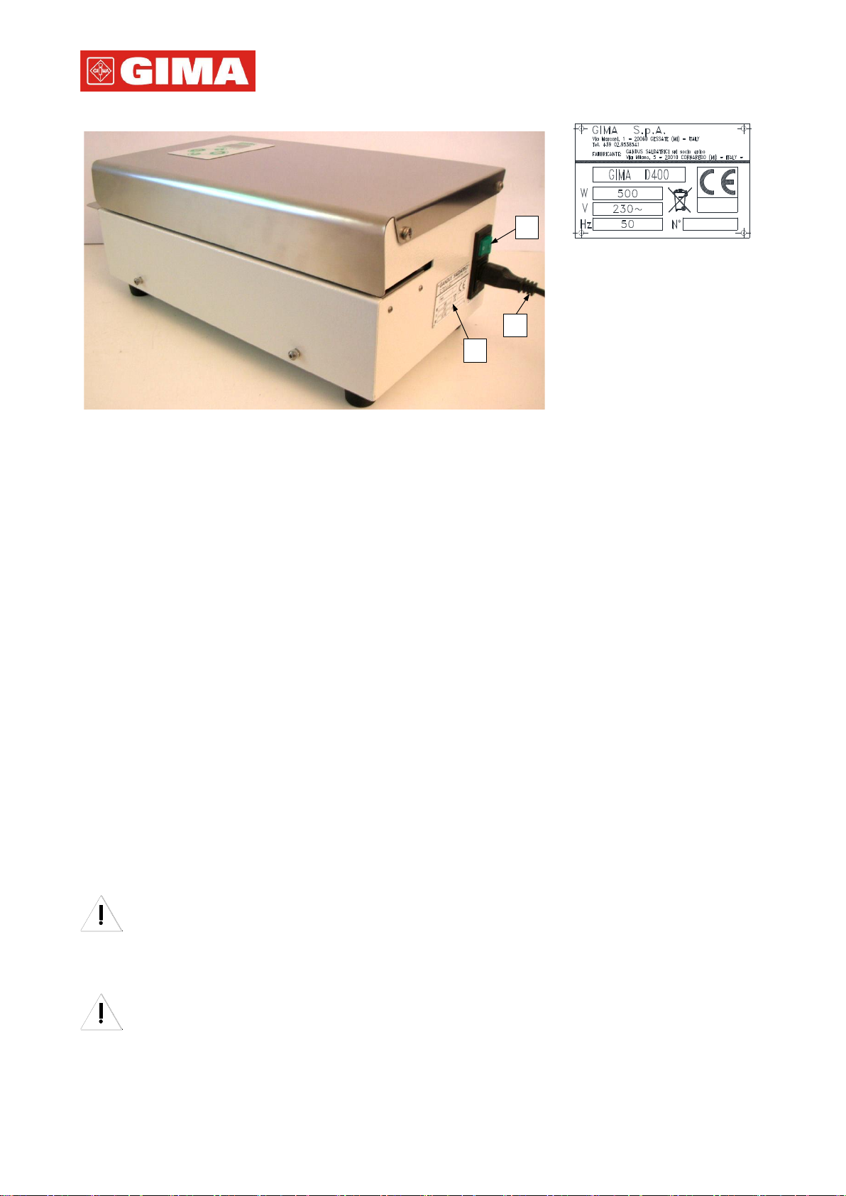
Power supply: 230-240V 50/60Hz or 100-115V 50/60Hz
Power absorption 500 W
Acoustic emission level 70 dB(A)
Dimensions without accessories:
Width = 473 mm - Depth = 235 mm - Height = 181 mm
Net weight12,5 Kg
As for DIN 58953 P. 7 specifications
Built in accordance to the CE rules
Environmental working conditions: Temperature: from 5°C to 40°C (from 41°F to 104°F)
Humidity relative: 30% - 95% (without condensation)
GANDUS SALDATRICI S.r.l. socio unico reserves the right to modify the machines
they construct without any obligation respect to those previously supplied
1.5 Transport and moving
We suggest to use the original packing during the transport.
We suggest to handle with care and to keep the packing, in dry environment,
following the positioning symbols.
TO AVOID DAMAGE TO THE MACHINE, WHEN IT IS MOVED, IS
FONDAMENTAL TO PRESERVE THE ORIGINAL PACKING.
GANDUS SALDATRICI S.r.l. socio unico declines every responsibility for eventual
damages to the machine, in case of shipments made without the original packing
To avoid damage when unpacking and for subsequent movements, act only below the
basement.
The heat-sealer can be damaged if lifted or moved using other parts such as
casing, conveyors, etc.

G I M A D 4 0 0
1.4
1.6 Safety rules
WARNING
THE OPERATOR MUST BE PROPERLY TRAINED AND HAVE FULL
KNOWLEDGE OF THE CONTENTS OF THIS MANUAL
Before electrical wiring, check if the data on the identification plate (pict.1.2)
corresponds to the local power supply
WARNING
CONNECT THE MACHINE ONLY TO A POWER SUPPLY WITH A PROTECTIVE
DEVICE AGAINST OVERVOLTAGE AND DISPERSION TO EARTH, IN
ACCORDANCE WITH THE SAFETY RULES AND CORRECTLY SIZED.
WARNING
UNPLUG THE MACHINE FROM THE MAIN POWER SUPPLY (N.2-PICT.1.1)
BEFORE ANY MAINTENANCE OPERATION.
Do not operate with the heat-sealer if the safety panels are open or removed.
Here there are the most important suggestions for the safety and good maintenance of the
machine:
To ensure its good function, keep the heat-sealer clean.
Before cleaning procedures on the heat-sealer machine unplug it (n.2-pict.1.1) from the
main supply.
Do not clean the heat-sealer with fluid or spray cleaners. Wipe the outside with a
slightly moist cloth and clean the inside with compressed air.
Never introduce in the sealing area anything but the bags to seal.
Do not introduce in any opening of the heat-sealer machine metallic objects, to avoid
electrical shocks.
The heat-sealer must be used only indoor and in a dampness free environment.
Temperature: from 5°C to 40°C (from 41°F to 104°F)
Humidity relative: 30% - 95% (without condensation)
Do not operate with the heat sealer in environments with risk of fire or explosion.
Do not use the heat-sealer in packaging of inflammable, corrosive or explosive
substances or in any case with dangerous products for the operator.
Use only original spare parts.
It is advisable to have the heat-sealer machine checked by a qualified technician every
year.
Do not change the set parameters while the heat-sealer is working.
In case of replacement of the fuses check that they are at the same value

G I M A D 4 0 0
1.5
Safety Signs
Signs
DESCRIPTION
General Warning
Burns due to temperature dangerous warning
Electricity Danger - Dangerous Voltages
1.7 To discard the machine
According to the DIRECTIVE 2012/19/EU rules this symbol
indicates that the device, when its work-life is ended, must not be
discarded as a urban waste.
It can be given to a suitable discharging centers of the electronics
and electric equipments or delivered to the dealer if you purchase
an equivalent device.
The device owner is responsible for the delivery in to the
discharging centers.
To get more informations about the discharging system, we
suggest you to contact your local discharging waste service.
The right discharging of the disuse devices avoids such a negative consequences
to the ambience and the human health.

G I M A D 4 0 0
2.1
2. INSTRUCTIONS FOR USE
2.1 Installation
The equipment can be used in any working environment that is dry and without excessive
dust, according to the chap.1.6
Place the sealer on a work surface, leaving an enough large space in front of it for the
bags to run over and on the sides the space for the introduction and exit of the bags from
the machine.
Be sure that the heat sealer is at least 30 mm from the back wall in order to allow a
perfect release of the heat produced inside and that on the sides there is the necessary
space to allow a an easy loading and unloading of the bag that are being sealed.
2.2 Pouches introduction adjustment
To easily open the sealed medical pouches, it is necessary to leave a free edge over the
seal.
According to the specific needs, it is possible to obtain a free edge from 0 to 30 mm. doing
as follows:
- loosen the locking knob (n.1-pict.2.1) and move it:
on the right to reduce the free edge over the seal (min. 0 mm)
on the left to increase the free edge over the seal (max to 30 mm)
-at the end of this operation, lock the knob (n.1-pict.2.1)
1
2
3
2
4
1
pict.2.1
1
Knob to infeed guide
2
Infeed guide
pict.2.2
1
General luminous switch
2
Plug of the general
switch
3
Socket of the supply
cable
4
Power supply cable

G I M A D 4 0 0
2.2
2.3 Electrical wiring
Check that the main luminous switch (n1-pict.2.2) is switch off, in the " 0" position (OFF).
Introduce the socket (n.3-pict.2.2) of the main power supply cable (n.4-pict.2.2) into the
plug of the general switch (n.2-pict.2.2) before inserting the plug of the supply cable (n.4-
pict.2.2) into the single phase socket.
Respecting the chapter 1.6, insert the plug of the main power supply (n.4-pict.2.2) into the
single phase socket with protected earth from an anti-electrical shock magnetothermic
switch, after checking that the data of the plate are the same of the power supply net.
2.4 Switch on the machine
Switch on the machine through the main GREEN luminous switch (n.1-pict.2.2) on position
“ I” (ON).
The display lightens and the first screen that is displayed on the software version of the
machine:
After that the sealer does an autodiagnostic on the main components and evaluates the
sealing paramerters values. In case there is any alarm situation, the dilpay will show the
relative bad functioning (see chap.3); for ex. the low temperature alarm:
After this diagnostics, if there is no alarm, the display shows the measured temperature on
sealing bars ( T) and the set temperature ( Ts ):
pict.2.3
After switching on the machine, the sealing bars begin their heating; when the current and
set temperature are at the same value, the sealers is ready to be used.
The temperature stabilization takes some minutes.
F i r m w a r e
B _ 2 . 0 0
T = 1 6 0 ° C
T s = 1 6 5 ° C

G I M A D 4 0 0
2.3
2.5 First employ
WARNING:
-In order to avoid imperfect seals, bad functioning and/or machine stops, the
operator always must introduce into the machine the pouch well stretched as
shown on the pict.2.4.
pict.2.4
-The DIN 58953 P7 rules requires the pouches can be filled up max until ¾ of
their length
-Do not apply any kind of label and/or adhesive on the pouches near the
sealing area
-For proper operation of the sealing machine, avoiding alarms, it is important
that the pouches are introduced with a relative distance not less than 50 mm.
After switching on the machine (see par.2.4) and reaching the set sealing temperature, the
machine is ready to do the first seal.
When introducing the first pouch into the sealing machine through the infeed guide the
motor will automatically start running and the pouch will be feeded into the machine.
If the operator does not introduce any pouches into the sealing machine for approx. 10
sec, the gearmotor will stop automatically, in order to avoid useless consumes; it will start
again running automatically when a new pouch is introduced.
OK

G I M A D 4 0 0
3.1
3. CONTROL PANEL
In this section will be described the panel commands, which can be done by the operator
to manage the working adjustments and the desired machine configuration.
The command panel allows the operator to visualize, set and/or modify the sealing
temperature parameters.
Main menu visualized are two:
-VISUALISATION MENU : it contains the working views
-SETTING MENU : enables changes in the working settings
3.1 Keys symbols
pict.3.1 (contro panel )
The keyboard keys show the following functions:
F
-
Key with a double function: to shift from a view to the following ot get out,
without saving, from the selected section
Set
-
Key with a double function: to enter the menu from settings of confirm the
changes made
Up
-
key to increase the selected date (number or character)
Down
-
key to decrease the selected date (number or character)
D400

G I M A D 4 0 0
3.2
3.2 Operative visualizations
When starting the machine (see par.2.4) the display visualizes the firmware version and
the software elaborates a diagnostic of the machine. Once completed, in case of no
alarms or immediately after stopping the alarm, the view concerning the sealing
temperature is visualized:
1)
where:
Tis the real sealing temperature, Ts is the set la sealing temperature
If the sealing temperature is not between (Ts+5°C) and ( T S - 5 ° C ) the
machine stops the transport of the pouches and the alarms is activated.
3.3 Operating settings
Through the operating settings it is possible to set the working mode and all date
concerning the pouch to be sealed.
3.3.1 Logic selection and changes of setting views
-By pushing the key SET from the visualization view 1, the machine shows the first setting
view ( A ). By pushing many times the key F a rotating menu is shown: it goes from one
view to another.
-To come back to view 1) of temperature it is necessary to confirm, pushing the SET key,
the view EXIT (point “ C) “ par.3.3.2) or it is enough do not execute any changes for 90
seconds long.
-To select and change a setting view, it is necessary to push the SET key, the date
(number or character) will start blinking and it will be possible to change it.
Cases:
-If the date is selected from a set of predefined options (see L A N G U A G E ), by
pushing SET the whole date will blink and it will be possible to visualize the
following date by pushing the keys Up and/or Down; by pushing the SET key the
choice will be confirmed and the date will stop blinking.
-If the date is a numeric value (see TEMPERATURE), by pushing SET the
whole date will blink and it will be possible to increase it through the key Up or
decrease through the key Down; by pushing then key SET change and date will
be confirmed and the date will stop blinking.
T = 1 7 5 ° C
T s = 1 8 5 ° C

G I M A D 4 0 0
3.3
NOTE
-By pushing keys Up and/or Down the characters will change quickly; by
pushing once the key the change will be slow.
-By pushing key Fwith the blinking date no change will be done and the
following view of the setting menu
3.3.2 Setting views sequence
Following the proposed views sequence; push key Fto move from one view to the
following.
A) Sealing temperature
Sealing temperature in °C ( Ts) ; temperature value can be
between 10°C and 200°C
B) Language display
Up to 5 languages can be set the display of the machine:
ITALIAN, ENGLISH, FRENCH,
GERMAN, SPANISH.
C) Leaving the settings menu
By pushing key SET the visualization view 1) of temperature will
be proposed.
By pushing key Fthe view A) of the sealing temperature will be
proposed and the cycle of the settings views will start again.
3.4 Machine alarms
When an alarm condition arises, the machine shows an acoustic signal (beep) and 2
blinking views are visualized, one after the other: the first with the alarm code (for the
codes list see Tab.1) and with the operation that needs to be executed to stop the alarm,
the second with a description of the aberration.
S E T T E M P
Ts=150°C
LANGUAGE
ENGLISH
P U S H S E T
E X I T

G I M A D 4 0 0
3.4
By pushing key SET the acoustic signal stops and the two blinking views disappear. In
case one of the sealing parameters (temperature, strength, speed) is beyond the set limits,
in visualization views 1) and/or 2) the relating number value will blink. If alarm is blocking
(see Tab.1) the motor of the machine stops and does not start.
Example alarm views:
after pushing key SET, in the visualization view 2) the strength value blinks
Tab.1 –ALARMS LIST
Cod.
Message
Blocking
Alarm
Aberration Description
Action
11
HIGH
TEMPERA
T
YES
High Temperature, beyond
the superior limit
Push SET per reset alarm e
wait
12
LOW
TEMPERA
T
YES
Low Temperature, below the
inferior limit
Push SET per reset alarm e
wait
13
DAMAGED
P R O B E
YES
Probe bars temperature
broken
Probe replacement
14
INT
TEMP
F A U L T
YES
Probe of the board damaged
Board replacement
15
CALIBR.
PID
YES
Error heating parameters
Execute Auto tuning
71
SEALER
VENTILA
T
NO
Temperat. inside machine
equal to 50°C (prealarm
temperat. machine)
Reset alarm and check cause
72
INTERNA
L
TEMPERA
T
YES
Overcoming temperature limit
inside the machine (higher
internal temp. equal to 60°C)
Reset alarm and check cause
41
SET
LOSS
NO
Settings loss
Reset alarm and check cause
and consequences
Cod.
Message
Blocking
Alarm
Aberration Description
Action
T = °C
T s = 1 8 5 ° C

G I M A D 4 0 0
3.5
3.5 Block –Unlock display
The display lock is a software option which prevents any change in the recorded
parameters/data; with a locked display all views of all menu can be visualized but it is
impossible to carry on any change.
To lock or unlock a display, it is necessary to push key Fduring the starting phase of the
machine.
If the lock or unlock procedure has been correctly carried on, the system will show the
initial view.
Immediately followed by the view:
X) or Y)
If the system has been locked, once you enter the menu of operative settings, the system
shows the view X) for 3-4 seconds before showing the initial view of the menu.
DISPLAY
LOCKED
Firmware
v . 0 1
UNLOCKED
DISPLAY

G I M A D 4 0 0
4.1
4. CORRECT FUNCTIONING
4.1 Sealing temperature
The sealing temperature value has to be set according to the thickness, the kind and the
condition of the material to seal.
Check that the set temperature corresponds to the suggested one by the bags
manufacturing house.
Should this value be unknown, following a table containing indicative adjustment values of
the heat sealer, according with the material used.
NORMAL STERILIZATION BAGS (*)
MATERIALS
PAPER/POLYPROPYLENE-
POLYESTER
HEAT SEALABLE
PAPER
TYVEK
FLAT POUCH
150° - 160° C
150° - 170° C
120°-130° C
GUSSETED
POUCH
160° - 170° C
155° - 175° C
- - - - - - -
(*) GANDUS Saldatrici s.r.l socio unico takes no responsability for the given data reliability.
For other materials or in case of troubles in finding the correct temperature, please send
GIMA s.p.aa sampling of bags to allow comparative tests and calculate the relevant
adjustment values.
To set a new sealing temperature value see par. 3.3.
Make some tests to check the correctness of the new temperature value.
4.2 Sealing pressure
The sealing pressure is already set by the manufacturer according with all materials in
normal use.
In case you should need a pressure increase/decrease for special purposes see par.5.5.
4.3 Sealing quality
Aiming to obtain steady high quality seals, please follow these guidelines:
- during the sealing cycle the bag should not be submitted to any traction or moves;
- make sure that the part of the bag to be sealed is clean and dry;
- place carefully the mouth of the bag to be sealed inside the in-feed guide; during this
operation, remove the air in excess;
- keep the mouth of the bag spread out until it is fully introduced in the sealing area of the
machine; this will prevent from any damage to the sealing (see par. 2.5);

G I M A D 4 0 0
4.2
- never feed the pouches into the in-feed guide using a feeding speed higher than the
machine transport speed;
- pouches feeding too much fast, can interfere with the in-feed photocell characteristic that
might cause a transport stop;
- do not stop the sealer during the sealing, with the exception of emergency situations;
- should the bags be of small/medium size or with a light and not bulky contents, they can
be conveyed by the machine over the support surface;
Should the bags be heavier and larger, the entrainment will be easier by using the slip
rolls during the sealing (see par.9.1). The operator should in any case drive the bag
during the sealing process.
Never introduce into the machine bags on which labels or adhesive tapes are
applicated; this origins rests of material into the sealing tunnel, which causes
the bags jam into the machine.
To obtain perfect seals and to make the work easier, the DIN 58953 rules state
that the pouches must not to be filled more than the 3/4 of their length, letting
always not less than 30 mm between the content and the internal edge of the
seal.
4.4 Normal stop of the heat sealer
To switch off the heat sealer press the main GREEN luminous switch (n.3-pict.1.1) to the
position “ O ” (off).
With the exception of emergency situations, do not stop the machine during the
running of one or more pouches in the sealing area. This will avoid the overheating of
the bags and the burning of material.
4.5 Emergency stop
In case of emergency, unplug the power cord (n.2-pict.1.1) from the machine. This action
causes the complete disconnection of power supply and the consequent immediate stop of
moving parts.
After solving any issue, to restart the sealer it is necessary to act on the main the GREEN
light switch (n.3-pict.1.1) on " O " (off), reconnect the power cable and then run as
described at par.2.5.
Since the temperature during the stop has come down, you will have to wait several
minutes before the sealer will starts transport up to the temperature is reached.

G I M A D 4 0 0
4.3
4.6 Bag jamming
In case of a bag jamming into the machine, do as follows:
-Swith off the sealer acting on the main switch (n.3-pict.1.1) and disconnect
the power cable (n.2-pict.1.1).
-Do not rip the bag towards the external of the machine to avoid formation of bag
residuals, which could obstruct the sealing tunnel with a consequent jam of the following
bag.
To avoid jamming follow the instructions of par.2.5 and par. 4.3
2
5
1
3
4
5
2
1
pict.4.1 pict.4.2
1
Upper cover
1
Upper motor pulley
2
Screw upper cover
2
Reverse lever
3
Frame
4
Frontal cover
5
Screw frontal cover
4.6.1 Bag jamming in the pressure and/or printing zone
A) SIMPLE BAG JAMMING
Do as follows
-Swith off the sealer acting on the main switch (n.3-pict.1.1) and disconnect
the power cable (n.2-pict.1.1).
-Loosen the 2 screws (n.2-pict.4.1) and turn the upper cover (n.1-pict.4.1) until his total
Table of contents
Other Gima Food Saver manuals