Gingerway GW-9325 User manual

Gingerway Technologies Co.,Ltd
SmartC Ethernet Smart Gateway
SmartC Ethernet Smart Gateway with GSM
GW-9325/GW-9326
Instruction Manual
Enjoy the Life
201804 V1.3

Foreword
Dear users, sincerely thank you for choosing our products. For your convenience
of installing and using this product, please read this manual carefully before use.
Gingerway SmartC series of Ethernet smart gateways integrate Gingerway
mature product experiences in the eld of home automation and security alarm
system for many years. Based on Gingerway's own full digital wireless two-
way highly reliable internet of things network technology Z-Ginger® which
with large coverage and low power consumption, the ultra low power sensor
technology, multi-platform APP software technology, also combined with the
lasted Ethernet technology and cloud technology. They are the new generational
smart multi-use centra equipments fused with home automation and security
alarm system, they are the ideal products of device intelligent-controlling and
security alarm in houses, hotels, oces and emporiums .
Gingerway SmartC series of smart gateways must be used with Gingerway
smart switch, socket, curtain controller, IR transmitter, power strip, alarm
sensor, etc.
Keywords:
Terminal Node: The each gang light/socket/curtain/alarm sensor and other
devices, which can be controlled by the smart gateway.
Binding: Establish a secure connection between gateway and the terminal
nodes.
Device Control: Control the on-off state and arm-disarm state of single
terminal node.
Scene: The on-o state and arm-disarm state combination of multiple remote-
controlled terminal nodes. Eg: At the scene “Pastime”, the backlight in the
living room can be set to state ON while the curtain OFF and the television ON,
etc.
Contents
Main Features................................................................................................. 1
Explanation of Gateway Appearance........................................................... 2
Installation to Access Steps ........................................................................... 3
Operations on Gateway Panel....................................................................... 4
The Contents and Meanings of LCD Screen ............................................... 4
Operation on APP "ZGinger Mini " ........................................................... 5
Gateway Settings...................................................................................... 6
Gateway-General.................................................................................... 6
Gateway-Network ............................................................................. 6
Gateway-Password................................................................................ 7
Gateway-Backup & Restore .................................................................. 7
Device Settings-Alarm ........................................................................ 7
Siren Setting....................................................................................... 7
Local GSM Alarm Call ........................................................................ 7
Cloud Arm Notication ....................................................................... 7
Device Settings-Timer......................................................................... 7
Device Settings-Trigger....................................................................... 7
Tools-Set Control Panel Icon .............................................................. 8
Scene Settings........................................................................................... 8
Smart Device Binding.............................................................................. 8
IR Device Binding.................................................................................... 9
Scene Panel Setting.................................................................................. 9
FAQ ............................................................................................................... 10
Technical Parameters ...................................................................................11
Warranty Terms ........................................................................................... 12

Main Features
√ Z-Ginger® full-digital, highly reliable, large coverage, low power
consumption internet of things wireless two-way network
√ With built-in 10/100M Ethernet, high stability and reliability
√ Support up 16 scenes, 64 devices, 128 bindings
√ Support all the smart home and alarm equipments with Z-Ginger® protocol
√ Backlit graph LCD screen
√ Universal quad-band GSM module (GW-9326)
√ Backlit high-sensitivity capacitive toch keyboard, support "wake-on-approach"
function
√ 8 user-denable touch key scenes
√ With bulit-in siren
√ Tamper alarm
√ Built-in Li-Ion rechargeable battery, ensure gateway working for 12 hours in the
even of a power failure (GW-9325)
√ Support 1 gang external wired sensor input, 1 gang alarm output and 1 gang
pulse output
√ Android/iOS/Windows multi-platform, multi-language APP
√ Devices fully congured in APP, simple and intuitive
√ Built-in cloud service, all the equipment operations can be finished in cloud
server
√ Adopt SSL/TLS encryption technology to implement cloud communication
√ Support cloud rmware upgrade
√ Support timing, sensors linkage trigger controlling
√ Support data backup and restore
√ Low battery notication of alarm sensors
√ Field voice monitoring (GW-9326)
√ Local GSM call/SMS + APP push alarm notication
COM +12V PUSH SPK IN1
ON
OFF
RESET
GSM
12V1A
DC
Front side
Back side
123
456
789
0
Arm Scene
Arm Indicator
Scene3(At home)
Microphone
RESET key
"COM" is common port (negative terminal). "IN1" is 1 gang alarm sensor input, can connect 1 gang
normally-open wired sensor; "SPK" is 1 gang wired siren output (active low, maximum sink current
200mA); "PUSH" is 1 gang disarm unlock pulse output (active low), 500MS pulse will be sent out
to control electic lock when gateway disarmed; "+12V" is 12V power output, can supply power for
external wired sensor(maximum 200mA). Please refer to the detailed connection method of terminals
at page 9 "Addition"
Attention: "Programming jumper"is only used for maintenance, do not change its position.
Siren
Li-ion Battery Pack
7.4V 900mAh
RUN PROG
LCD screen
Disarm Scene
Disarm Indicator
Scene4(Go out)
Scene5(Get up)
Scene6(Pastime)
Scene7(Lunch)
Scene8(Sleep)
Backspace Enter
Bracket hole
Standby battery
Tamper switch
Power switch
Programming jumper
Power adapter port
SIM card holder
Terminals
Explanation of Gateway Appearance
1 2
ETHERNET
Ethernet interface

Installation to Access Steps
3 4
1.Draw the position of 2 bracket screw holes point to the wall, punch holes at the position by
drill, then insert anchorings to x the bracket on the wall. The bracket can also be installed at
the existing mounting box(86*86mm) by screws. After the bracket xed, take the gateway to
seize the bracket and to be xed.
2. Insert a SIM card and x it(GW-9326). The SIM card must be GSM standard, able to
dialing and answer calls, and with SMS text function.
3. Plug LAN cable to the Ethernet interface.
4. Plug the matching 12V power adapter into power port, then slide the power switch to ON
position,
5. Download and install the APP "ZGinger Mini" into your smart terminal. Android user can
get it on "Google Play", Apple user can get it on "APP Store", Windows user please download
it at our website
http://www.gingerway.com/En_Gingerway_Download2.html
6. Scan the QR code on the back of gateway or manually enter gateway default IP address
"192.168.1.1", to add this gateway into APP. Use the "admin" account (default password is
123456) that can login this gateway via "Cloud"; When login the gateway via "Local", the used
IP address in gateway login interface must be same as the current gateway IP address which
showed on the LCD screen.
Restore factory settings: Slide the power switch to OFF position, then slide it to ON
position. When the screen is on, long press RESET key for 10 seconds, the gateway will
be restored to factory settings (all data will be deleted except backup data ).
The keys on the left and right columns of gateway panel are 1st to 8th scene of gateway.
Press "Arm Scene" key, gateway will execute "Arm" scene, all the alarm sensors which in this
gateway will get into arm state. If "Arm" scene executed successfully, the gateway will make a
long tone of "Di", and arm indicator is on;
Press "Disarm Scene" key, input "user" account password (default password is 123456) then
press "Enter" key, gateway will execute "Disarm" scene, all the alarm sensors which in this
gateway (except 24-hour armed sensors) will get into disarm state. If "Disarm" scene executed
successfully, the gateway will make 2 short tone of "Di", and disarm indicator is on;
At disarm state, press the rest 6 scene keys (3-8) can start the relevant gateway scenes.
Note: Operating on gateway panel, only the gateway under disarm state can the rest 6
scenes be executed. If you want to start these scenes, please disarm the gateway rstly.
Operations on Gateway Panel
The Contents and Meanings of LCD Screen
①②
③
④
⑤⑥⑦
①: SIM card signal.SIM card detected shows , no SIM card detected shows
.
②: Current network mode of gateway
:Station mode, cloud server hasn't been connected
:Station mode, cloud server has been connected
③:Current gateway IP address
④:Displayed information as AP mode or alarm information
⑤:The quantity of alarm sensors which at arm state
⑥:The quantity of alarm sensors which at disarm state
⑦:The quantity of 24-hour armed sensors
External 12V DC power supply
Connection example of terminals:
COM +12V PUSH SPK IN1

Operation on APP "ZGinger Mini "
Gingerway SmartC series of gateways must be used with our APP "ZGinger Mni"
(version V2.0 and above). Without going through browser, you can directly bind/
delete/edit devices and scenes on the APP interface.This version APP adopts SSL/
TLS encryption mechanism to protect the security of user data.
You can set the scene/device icons as you like, self-dene your favorite background,
and add the required devices to home interface.
Users can upload the gateway data to Gingerway cloud server. If other users want to
control this gateway, only click "Cloud Synchronize" can nish it, without resetting.
All the operations can be executed if login gateway by "admin" account(default
password is 123456); Login gateway by "user" account (default password is 123456)
can only control the gateway devices.
Gateway icon box only display the
quantity of non 24-hour armed sensor
The corresponding 1st-8 th scenes of
gateway panel
There are 4 default scenes. The rst
two scenes are "Arm" and "Disarm",
they can't be deleted, users can only
change their names, all the alarm
sensors will be automatically added
into these two scenes. The other
scenes can be edited.
56
At the gateway home interface of APP "ZGinger Mini", click the menu key in the top left
corner will pop out the menu bar. Click "Edit" can enter ino APP edit state, you can view/
edit/add/delete the devices and scenes at edit state. Click the gateway icon box at edit
state can enter into "Gateway Setting" interface to set the gateway.
Gateway Settings
Gateway - General
1.On "General" interface, you can change gateway name, check and upgrade new
version.
2.Please set the cloud server address as "cloudhk.gingerway.com", and please set it as
"cloud.gingerway.com" if in mainland China. The cloud server which you used in the
login interface must be same as you set for the gateway.
3.For the reason of SSL/TLS encryption mechanism, please set the right date and time
for gateway.
Gateway - Network
Gingerway SmartC Ethernet series of gateways turn on "DHCP Enable" by default, the IP
address will be automatically assigned by gateway and can't be changed. Turn o the "DHCP
Enable", you can modify the IP address as your actual situation.
Attention: If the client login the gateway mainly via "Local", please turn o "DHCP
Enable" and set the IP address as a xed address.

Gateway - Password: For security reasons, please change the "admin" and "user"
passwords in time .
Gateway - Backup & Restore: Backup your current gateway data to the isolated storage
area of gateway, or restore it from the isolated storage area to gateway.
Attention: Backup operation only save the last one data, it will be retained even the
gateway was reset.
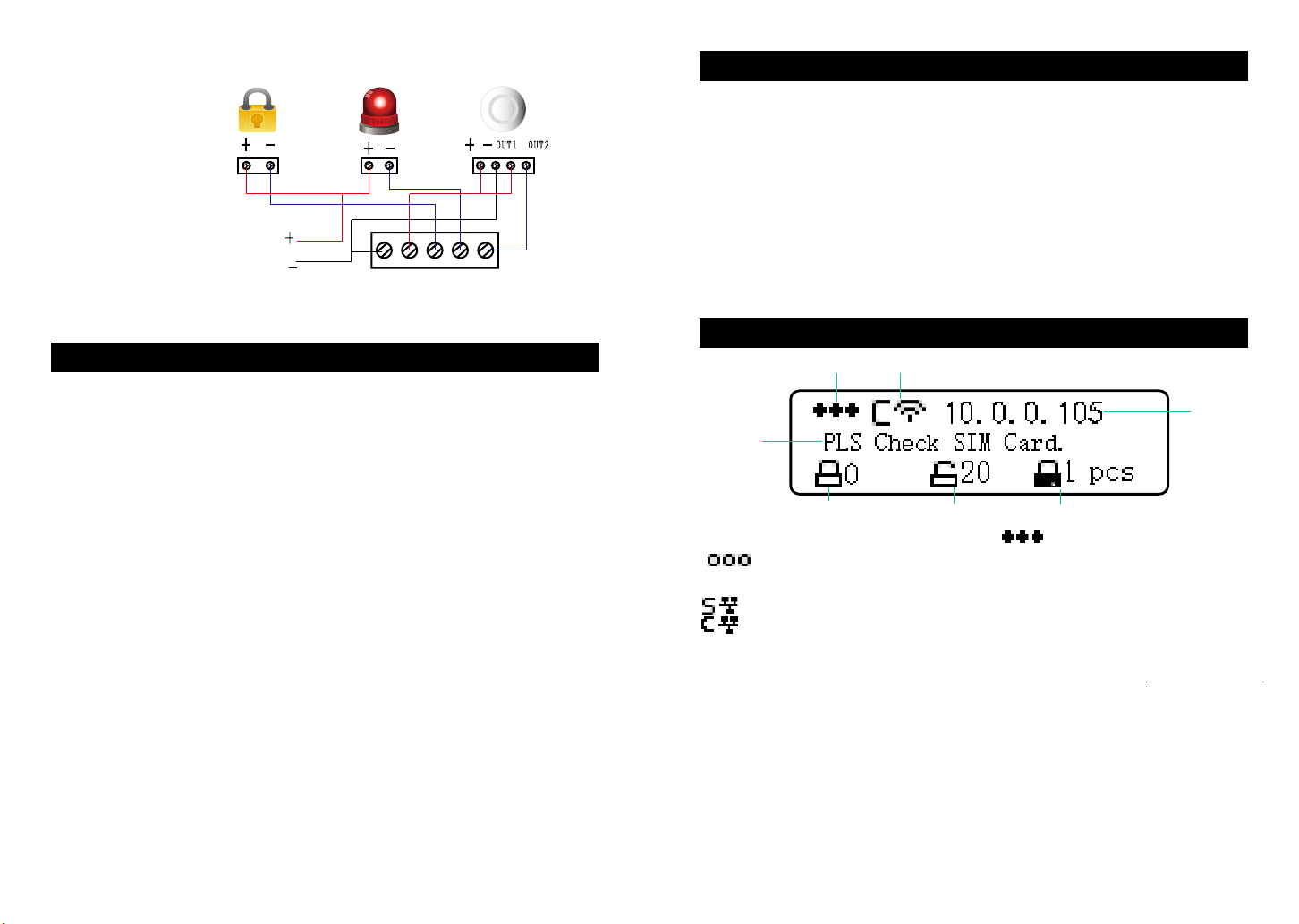
Device Settings - Alarm
Siren Setting:
Local siren alarm time set as 0 second, the built-in siren wouldn't hoot.
Ext.Siren alarm time set as 0 second, the "SPK" terminal wouldn't output the signal.
Local GSM Alarm Call(for GW-9326):
User can store 5 alarm phone numbers. When alarm occurs, the gateway will auto-dial
the prestored numbers in order and send out SMS message to notify users. Answering
the alarm call can voice motinor that current situation. You can also view the alarm
information on the SMS message, to arm and diarm the gateway by replying "1" and "2".
Cloud Arm Notication:
1. In non-mainland China, please use "APP Push" notiction. You can select 5 push
terminals from all the terminals which login the gateway via "Cloud" according to APP
ID (The APP ID at the bottom of login interface, with "*" marked is your own local APP
ID).
2. In mainland China, please use "Voice Call + SMS" notication. When alarm occurs,
the cloud server will dial twice and send send SMS message once.
Note: For now, Android system is not supported to use APP push cloud arm notication in
mainland China.
Device Settings - Timer: To set a timing to start the required scene automatically.
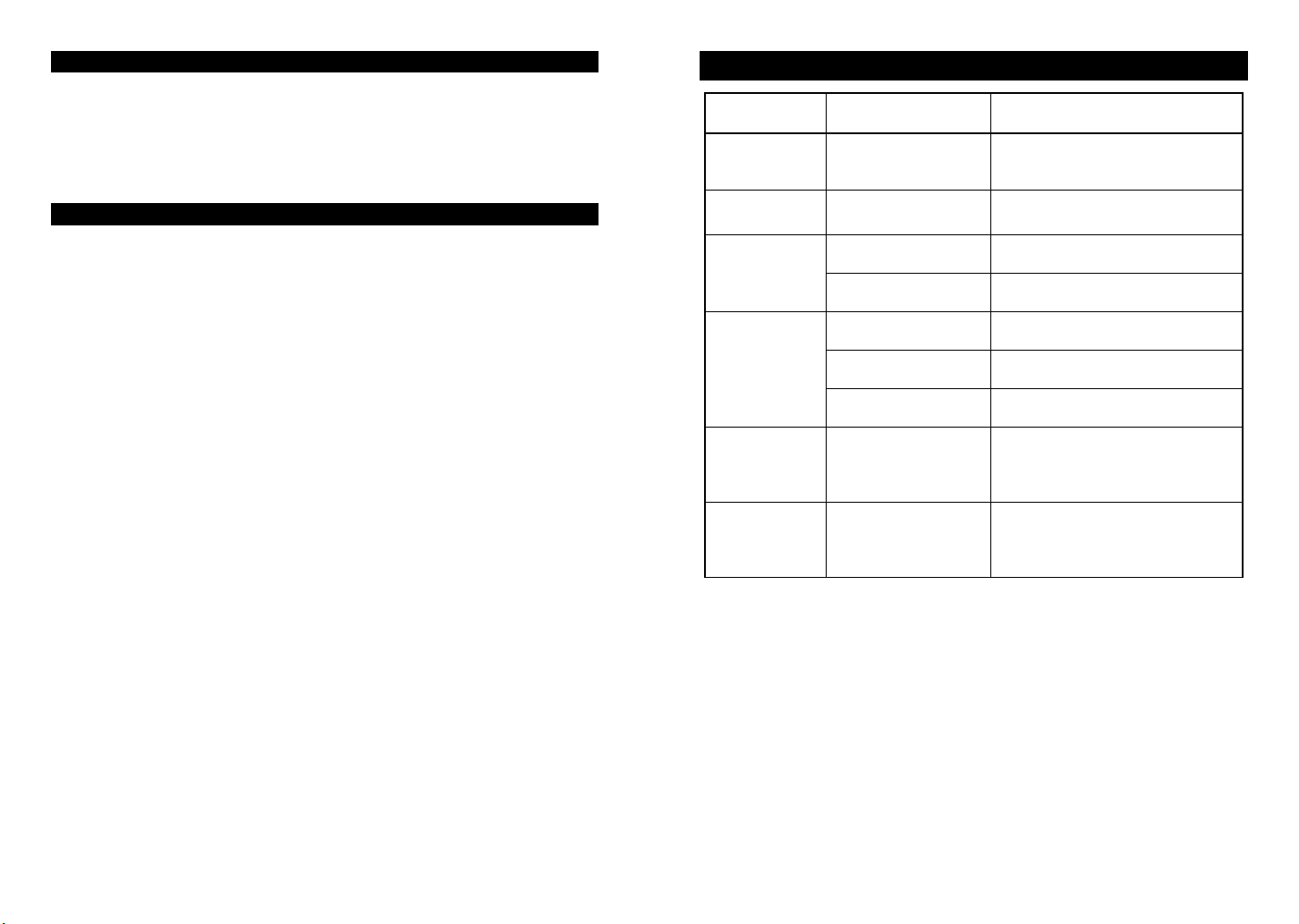
Device Settings - Trigger:
To set trigger, the trigger device should be bound with gateway rstly, like multifunction
sensor GW-4311. Enter into the trigger setting interface under APP edit state, select the
sensor and the scene which need to be triggered.
GW-4311 can detect the human body infrared, the changes of environmental temperature
and brightness. Therefore, the range of temperature and brightness can be set as a trigger
condition to trigger the required scene.
CH2 and CH3 are two external sensors. When PIR sensor, CH2 and CH3 set as "Invalid",
the detection signals have no eect on trigger. Set as "ON", indicates the trigger condition
is that human body infrared or external trigger signals being detected; Set as "OFF",
indicates the trigger condition is human body infrared or external trigger signals not being
detected.
You can also set the valid time and date for trigger according to your requirement.
7
Tools - Set Control Panel Icon
User can use this tool to send the name and icon of device and scene for Gingerway LCD
smart control panels (GW-1339,GW-7339). Sending icon image, only 48*16 B/W BMP
le is acceptable; Sending name, only supports up 8 English letters (If non-English name
is required, please convert the name to icon le rstly).
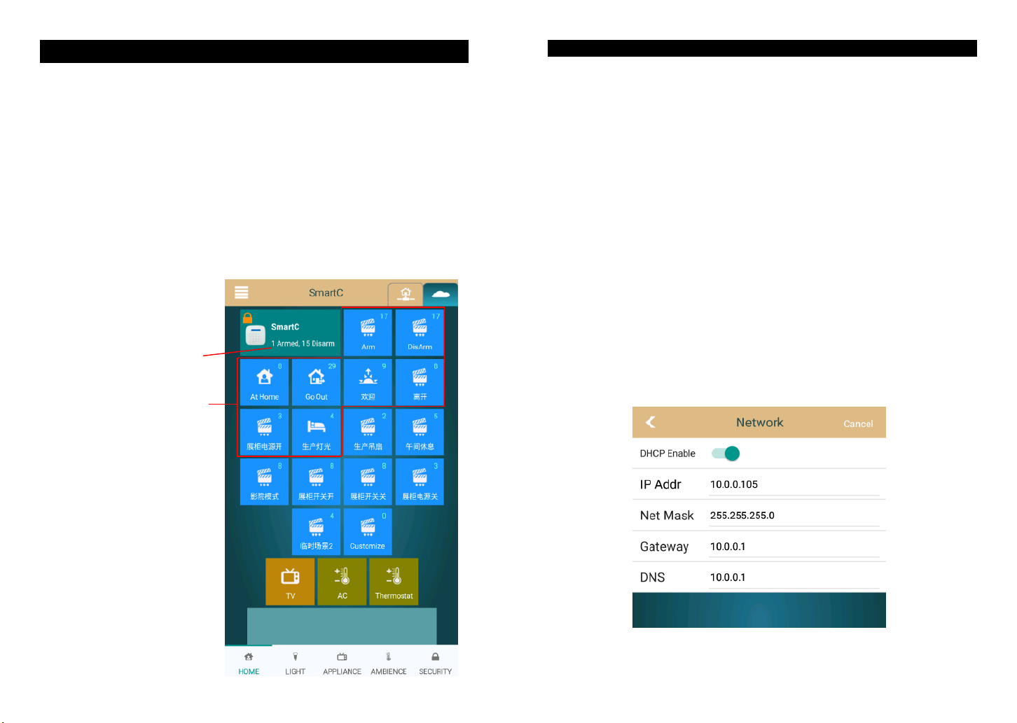
SmartC gateway supports up 16 scenes, and also supports the corss-gateway scenes.
Under APP edit state, press "+" to add new new scene, change the scene name in new
interface. Click "Add a Device" to add required devices into this scene, and select the
original status in this scene; Click "Add a Scene", you can add another gateway's scenes
into this scene.
Please bind your the terminal nodes (each light/socket/curtain/alarm sensor,etc.) with
your gateway before using.
Concrete method of binding:
1. Under APP edit state, click "+" to add new smart device and enter into interface "New
Smart Device". Set the device name.
2. Long press the on-o key or bind button of terminal node for 5 seconds, release your
finger after hearing a long tone of "Di" or the indicator keep continuously fliker, the
terminal node is going to send out a binding request.
3. In interface "New Smart Device", click "Start Binding", the gateway is going to
response to the binding request.
4. If the new interface shows "Binding Success", then this binding succeed. Exit the
setting interface and press "Done" to quit edit state, then you can control the terminal
node in APP control interface
5. If the new interface shows "Binding Failure", then this binding failed, please rebind it
again.
Attention: When the bound smart device is external sensor, it can be checked as "24-Hour
Armed", this sensor can't be disarmed after "24-Hour Armed" checked. If your external
sensors are gas sensor, smoke sensor or other sensors which should be alway in arm state,
please check the "24-Hour Armed".
Scene Settings
Smart Device Binding
8

Under APP edit state, click"+" to add "AC RC" or "TV RC" to home interface, set
the name in the edit interface. Edit nished, then you can bind the IR device.
(The binding method is same as Gingerway smart RC devices bind IR devices, you
can refer to the manuals of Gingerway IR transmitter and smart RC devices for the
detailed method)
IR Device Binding
Scene Panel Setting
FAQ
Malfunction Reason Solution
No response of
operation on
gateway panel
The power switch hasn't
been turned on
Open the the back cover of gateway and
slide the power switch to ON position
Gateway can't
control devices
The devices haven't been
bound with gateway
Bind the devices with gateway refer to
the instructions
Local GSM alarm
notication can't
be received
The local GSM alarm call
has been set
Set your phone number into local GSM
alarm calls
The charge of the SIM
card is overdue
Recharge the SIM card in time
No response after
inserting SIM card
The direction of SIM card
is wrong
Reinsert SIM card according to the
identier
Power on before SIM
card inserting
Insert SIM card rstly, then power on
gateway
The SIM card is not GSM
standard
Use the GSM standard SIM card
Unable to login
the gateway via
"Local"
The IP address used in
login interface is dierent
as the current gateway IP
address
Modify the IP address in login interface
to the current IP address of gateway
Unable to login
the gateway via
"Cloud"
The cloud server used in
login interface is dierent
as what you have set for
gateway
Change the cloud server in login
interface to which you have set for
gateway
9 10
"Scene Panel" is mainly aimed at Gingerway trigger type smart control panel and
scene controller for gateway(like GW-7339, GW-7335,). The panel can directly
trigger the scene and device which in gateway.
Firstly, bind gateway with smart control panel or scene controller . Under App edit
state, click the required panel icon in "HIDDEN" interface to enter into the setup
interface, select the device or scene which this panel will trigger. Setting nished,
then you can control the device or scene on the smart control panel or scene controller.

Power supply 12VDC 1A
Current Standby current:﹤120mA
Alarm current:﹤300mA
Built-in standby battery 7.4V 900mAh Li-Ion battery
Standby time of battery GW-9325: 12 hours
GW-9326: 8 hours
RF
Operating frequency: 433MHz
Transmit power: ~10dbm
Receiving sensitivity: ≤ -105dbm
Coverage: about 30m indoor, 100m barrier free
Ethernet 10/100M
GSM (GW-9326) Quad-band: GSM850, EGSM900, DCS1800,
PCS1900
Siren >90db
Maximum quantity of
controllable devices
64
Maximum quantity of
controllable scenes
16
Maximum quantity of
controllable bindings
128
Operating Temperature 0-60℃
Relative Humidity ≤ 80% (Non-condensing)
Dimensions (L * W * H) 135mm×135mm×24mm
Weight 330g
Shenzhen Gingerway Technologies Co., Ltd.
Address: 3-Floor, Building A6, Xingye Industrial Park, Zhongshanyuan No.2 Road,
Nanshan District. Shenzhen, Guangdong, China.
Tel :0755 -28779595 Fax :0755 -28779405
Website: www.gingerway.com
Gingerway products are guaranteed for 2 years since the date of purchase. During the
warranty period, if Gingerway products malfunction(not contain articial damages) under
normal circumstances, they can be free repaired or exchanged at local dealer with the
purchase invoice.
1. If due to quality failure during the warranty period, the maintenance is free in rst year,
only the component cost will be charged in the second year.
2. Disassembling Gingerway product components without the permission of our company
or the local client center, our company will no longer bear the free warranty responsibility
.
Note: Shenzhen Gingerway Technologies Co., Ltd reserves the right of nal explanation
for above terms.
0678
Warranty TermsTechnical Parameters
11 12
This manual suits for next models
3
Table of contents
Other Gingerway Gateway manuals