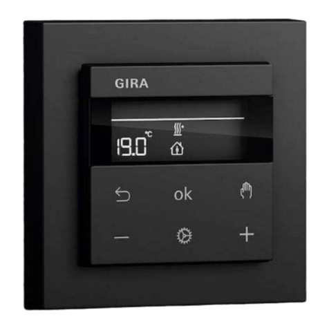
Gira System 3000 User manual

System 3000
Relay switching insert 2-gang
Relay switching insert 2-gang
Order no.: 5404 00
Operating instructions
1 Safety instructions
Electrical devices may only be mounted and connected by electrically skilled persons.
Serious injuries, fire or property damage possible. Please read and follow manual fully.
Danger of electric shock. Always disconnect before carrying out work on the devise or load.
These instructions are an integral part of the product, and must remain with the end customer.
2 Intended use
– Switching of lighting and motors
– Mounting in appliance box according to DIN 49073
– Operation with suitable cover
3 Product characteristics
Product characteristics
In combination with 2-gang push-button top
– Two independent outputs
– Time function for output a2 adjustable
– Connection of extensions possible
In combination with 1-gang push-button top
– Output a2 switches depending on output a1 e.g. to switch on ventilation, depending on
the lighting, and switch it off with a delay.
– Switch-on delay of output a2 adjustable
– Run-on time of output a2 adjustable
– Connection of extensions possible
4 Operation with 2-gang push-button top
Switch load
– Left: operation of output a1.
– Right: operation of output a2.
■ Press push-button.
Output a1, a2 switches on and off.
Extension unit operation
Operation via 3-wire extension with 2-gang push-button top: Press top to switch on, press bot-
tom to switch off.
A 2-wire extension or push-button always switches both outputs.
Rotary dimmer extension only switches output a1.
Time function
If a time function is set for output a2 (see Setting the time function/run-on time), it switches off
after the set time has expired. The time function starts as soon as output a2 is switched on. To
terminate the time function prematurely, output a2 must be switched off manually.
The time function cannot be restarted by pressing again.
1 / 6
82401702 27.11.2018

System 3000
Relay switching insert 2-gang
5 Operation with 1-gang push-button top
Switch load
With the 1-gang push-button top, output a2 switches depending on the switching state of output
a1.
■ Press push-button.
Output a1 and a2 switch on and off.
Extension unit operation
Operation using 2-wire extension, push-button or rotary dimmer extension corresponds to oper-
ation on the main device.
Operation via 3-wire extension with 1-gang push-button top: Press top to switch on, press bot-
tom to switch off.
Activate switch-on delay of output a2
For output a2, a switch-on delay of 3 minutes can be switched on. It starts as soon as output a1
is switched on. If output a1 is switched off again before the switch-on delay has expired, output
a2 remains switched off.
Requirements: Both outputs are switched off.
■ Press the button cover over entire surface for longer than 4 seconds.
Both outputs are switched on immediately. After 4 seconds, output a2 is switched off.
■ Release the push-button top.
The switch-on delay is switched on.
Deactivate switch-on delay for output a2
Requirements: Both outputs are switched off.
■ Press the button cover over entire surface for longer than 4 seconds.
Output a1 is switched on immediately. After 4 seconds, output a2 is also switched on.
■ Release the push-button top.
The switch-on delay is deactivated. Both outputs are switched on simultaneously.
Run-on time
For output a2 a run-on time can be set (see Setting the time function/run-on time). It starts as
soon as output a1 is switched off.
If output a1 is switched on before output a2 is switched off, the run-on time of output a2 is only
restarted if:
– output a1 is switched off when the switch-off delay for output a2 is switched off.
– output a1 is switched off after more than 3 minutes when the switch-on delay for output a2
is switched on.
6 Operation with motion detector as standard or timer with display
In combination with a motion detector as standard or a timer with display, the switch insert be-
haves as with a 1-gang push-button top. The motion detector switches on output a1 and
switches it off again after the run-on time of 2 minutes set in the motion detector has expired.
The timer switches output a1 on or off manually or automatically. Output a2 switches immedi-
ately or with a time delay, depending on output a1.
Switch-on delay
The switch-on delay for output a2 is switched on or off at the insert.
– For this, a 1-gang push-button top is placed on the insert instead of a motion detector and
is then replaced by the motion detector after the switch-on delay has been set.
2 / 6
82401702 27.11.2018

System 3000
Relay switching insert 2-gang
– Press timer with display and the button ƞ and Ɵ simultaneously for longer than
4 seconds.
Run-on time
The run-on time for output a2 is set at the insert as described (see Setting the time function/run-
on time).
7 Operation with Bluetooth motion detector
During movement, the motion detector switches output a1 depending on the brightness and out-
put a2 independently of the brightness and with a time delay. After the run-on times set in the
motion detector have expired, the motion detector switches off the outputs again.
Switch-on delay
The switch-on delay for output a2 is controlled by the insert and is 2 minutes in the default set-
ting. Output a2 is only switched on if movement is detected during the active switch-on delay.
Run-on time
The run-on time for output a1 is set in the motion detector via app. The run-on time starts when
movement is no longer detected.
The run-on time for output a2 is set in the motion detector and is 5 minutes in the default set-
ting. The run-on time for output a2 starts when movement is no longer detected and output a1 is
switched off.
8 Operation with Bluetooth timer
In combination with a Bluetooth timer, the switch insert behaves as with a 1-gang push-button
top. The Bluetooth timer switches output a1 on and off manually or automatically. Output a2
switches depending on output a1. The switch-on delay and run-on time for output a2 are stored
in the Bluetooth timer. The switch-on delay for output a2 is 2 minutes in the default setting and
the run-on time is 5 minutes.
Activate switch-on delay
■ Switch on output a1.
■ Press the left button of the Bluetooth timer over entire surface for longer than 4 seconds.
Output a1 switches off.
After 4 seconds, output a1 is switched on and a2 is switched off.
Deactivate switch-on delay
■ Switch on output a1.
■ Press the left button of the Bluetooth timer over entire surface for longer than 4 seconds.
Output a1 switches off.
After 4 seconds, output a1 and a2 are switched on.
9 Information for electrically skilled persons
DANGER!
Mortal danger of electric shock.
Disconnect the device. Cover up live parts.
3 / 6
82401702 27.11.2018

System 3000
Relay switching insert 2-gang
Connecting and fitting the device
Figure1: Connection diagram with optional extensions
(1) Button TEST
(2) Display LED and connection socket for cover
(3) 2-wire extension
(4) 3-wire extension/rotary dimmer extension
(5) Push-button, NO contact
Figure2: Clampable conductor cross-section
For protection, only the circuit breakers specified in the technical data may be used.
Observe the current carrying capacity: In total, the switching current for both outputs must
not exceed 16 A.
■ Connect the switch insert according to the connection diagram (Figure 1). Observe the
clampable conductor cross-sections (Figure 2).
Lit push-buttons must have a separate N terminal.
4 / 6
82401702 27.11.2018

System 3000
Relay switching insert 2-gang
The load at both outputs can be switched by briefly pressing the TEST button (1) (switch-
ing states: a1 on a2 off, a1 off a2 on, a1 and a2 on, a1 and a2 off).
Set time function/run-on time
■ Press the TEST button (1) for longer than 4 seconds.
LED (2) lights up in the colour of the set time, see table.
LED signalling
LED colour Set time
green Function off
white 1 minute
blue 5 minutes
yellow 30 minutes
red 60 minutes
■ Release the TEST button (1) briefly and press it repeatedly until the LED (2) lights up in
the colour of the desired time.
The set time is automatically saved after 30 seconds or after pressing the TEST button (1)
for approx. 4 seconds. When the LED goes out, the saving process was successful.
Overheating protection
The electronic overtemperature protection switches both channels off in the event of overtem-
perature. If the switch insert has sufficiently cooled down, it can be switched on again.
10 Technical data
Rated voltage AC 230 V~
Mains frequency 50 / 60 Hz
Standby load depending on the cover approx. 0.1 ... 0.5W
Ambient temperature -25 ... +45 °C
Storage/transport temperature -20 ... +70 °C
Switching current per device Σ 16A
Switching current per channel for 25°C
Ohmic 10 A (AC1)
Minimum switching current AC 100 mA
Motors 3A (cos φ0.68)
Connected load per channel for 25°C
HV-LED lamps typ. 500 W
Compact fl lamp. typ. 500 W
Incandescent lamps 1500 W
HV halogen lamps 1500 W
Electronic transformers 1000 W
Inductive transformers 625 VA
Fluorescent lamps, uncompensated 750 VA
Capacitive load 580 VA (70 μF)
Power reduction
per 5°C in excess of 25°C -5 %
5 / 6
82401702 27.11.2018

System 3000
Relay switching insert 2-gang
when installed in wooden or dry construction
walls
-15%
when installed in multiple combinations -20%
Number of extension units
2-wire, push-button unlimited
3-wire, rotary dimmer extension 10
Only use these circuit breakers 16A
Manufacturer Type
Schneider Electric 23617
ABB S201-B16
ABL Sursum B16S1
Hager MBN116
Legrand 03270
Siemens 5SL61166
11 Accessories
Operating top unit 2-gang Order no. 5362 ..
Operating top unit Order no. 5360 .., 5361 ..
12 Warranty
The warranty follows about the specialty store in between the legal framework as provided for
by law Please submit or send faulty devices postage paid together with an error description to
your responsible salesperson (specialist trade/installation company/electrical specialist trade).
They will forward the devices to the Gira Service Center. They will forward the devices to the
Gira Service Center.
Gira
Giersiepen GmbH & Co. KG
Elektro-Installations-
Systeme
Industriegebiet Mermbach
Dahlienstraße
42477 Radevormwald
Postfach 12 20
42461 Radevormwald
Deutschland
Tel +49(0)21 95 - 602-0
Fax +49(0)21 95 - 602-191
www.gira.de
6 / 6
82401702 27.11.2018
Other manuals for System 3000
12
Table of contents
Other Gira Relay manuals
