Bender IOM441-S User manual
Handbuch/Manual DE/ENIOM441-S_D00300_04_M_DEEN / 03.2022
IOM441-S/IOM441W-S
Relaisbaustein/Relay module
2 IOM441-S_D00300_04_M_DEEN / 03.2022
IOM441-S/IOM441W-S
IOM441-S/ IOM441W-S
Relay module
i
Part of the device documentation in addition to
this manual is the enclosed „Safety instructions
for Bender products“.
Ordering details
IOM441-S/ IOM441W-S
Relaisbaustein
i
Bestandteil der Gerätedokumentation sind neben
diesem Handbuch die „Sicherheitshinweise für
Bender-Produkte“.
Bestellangaben
Typ / Type Versorgungsspannung Us / Supply voltage UsArt.-Nr. / Art.-No.
IOM441-S DC 24V B95012057
IOM441W-S DC 24V B95012057W
Zubehöhr / Accessories
Stecker Kit Schraubklemmen / Plug kit screw terminals *) B95012901
Stecker Kit Steckklemmen / Plug kit Push-wire terminals B95012902
Mechanisches Zubehör / Mechanical accessoires *) Frontabdeckung + 2 Monateclips / terminal cover + 2 mounting clips B95012903
BB-Bus 4TE Steckverbindung / BB bus 4TE Connector *) Erfordert passende Leiterplatte am Basisgerät / Requires matching PCB on base unit B98110002
*) Im Lieferumfang enthalten /Within scope of delivery
Allgemeine Hinweise
Benutzung des Handbuchs
Dieses Handbuch richtet sich an Fachpersonal
der Elektrotechnik und Elektronik!
Lesen Sie das Handbuch vor Montage,
Anschluss und Inbetriebnahme des Geräts.
Bewahren Sie das Handbuch zum Nachschla-
gen griffbereit auf.
Kennzeichnung wichtiger Hinweise und Informationen
I Gefahr! bezeichnet einen hohen Risikograd, der
den Tod oder eine schwere Verletzung zur Folge
hat.
I WarnunG! bezeichnet einen mittleren Risiko-
grad, der den Tod oder eine schwere Verlet-zung
zur Folge haben kann.
I Vorsicht! bezeichnet einen niedrigen Risiko-grad,
der eine leichte oder mittelschwere Verletzung
oder Sachschaden zur Folge haben kann.
i
Informationen können bei einer optimalen
Nutzung des Produktes behilflich sein.
General instructions
Using the manual
This manual is intended for qualified personnel
working in electrical engineering and electronics!
Read the oparating manual before starting to
install, connect and commission the device.
Keep the manual with in easy reach for future
reference.
Marking of important instructions and information
I DanGer! idicates a high level of risk that will lead
to death or serious injury.
I WarninG! idicates a medium level of risk that can
lead to death or serious injury.
I caution! indicates a low-level of risk that can lead
to minor or moderate injury or damage to proper-
ty.
i
Information intended to assist the user in making
optimum use of the product.
Zeichen & Symbole / Signs & Symbols
Entsorgung / Disposal Vor Nässe schützen / Protect from wetness
Recycling / Recycling Vor Staub schützen / Protect from dust
RoHS Richtlinien / RoHS guidelines Temperaturbereich beachten / Note temperature range

IOM441-S/IOM441W-S
IOM441-S_D00300_04_M_DEEN / 03.2022 3
Schulungen und Seminare
https://www.bender.de/fachwissen/seminare
Lieferbedingungen
Es gelten die Liefer- und Zahlungsbedingungen der Firma
Bender. Sie sind gedruckt oder als Datei bei Bender erhält-
lich.
Für Softwareprodukte gilt:
„Softwareklausel zur Überlassung von Standard-
Software als Teil von Lieferungen, Ergänzung und
Änderung der Allgemeinen Lieferbedingungen für
Erzeugnisse und Leistungen der Elektroindustrie“
Kontrolle, Transport und Lagerung
Kontrolle der Versand- und Geräte-
verpackung auf Transportschäden und
Lieferumfang. Bei Lagerung der Geräte
ist auf Folgendes zu achten:
Entsorgung
Beachten Sie die nationalen Vorschrif-
ten und Gesetze zur Entsorgung des
Gerätes.
Weitere Hinweise zur Entsorgung von
Bender-Geräten unter
https://www.bender.de/service-support
Gewährleistung und Haftung
Dieses Handbuch und die beigefügten Sicherheitshin-
weise sind von allen Personen zu beachten, die mit dem
Gerät arbeiten. Darüber hinaus sind die für den Einsatz-
ort geltenden Regeln und Vorschriften zur Unfallverhü-
tung zu beachten.
Gewährleistungs- und Haftungsansprüche bei Per-
sonen- und Sachschäden sind ausgeschlossen aus fol-
genden Gründen:
– Unsachgemäße Verwendung des Gerätes.
– Unsachgemäßem Montieren, Inbetriebnehmen, Bedienen
und Warten des Gerätes.
– Nichtbeachten der Hinweise im Handbuch bezüglich
Transport, Inbetriebnahme, Betrieb und Wartung des
Gerätes.
– Eigenmächtigen baulichen Veränderungen am Gerät.
– Nichtbeachten der technischen Daten.
– Unsachgemäß durchgeführten Reparaturen
– Verwendung von Zubehör und Ersatzteilen, die Bender
nicht empfiehlt
– Katastrophenfällen durch Fremdkörpereinwirkung und
höhere Gewalt.
– Montage und Installation mit nicht empfohlenen
Gerätekombinationen.
Training courses
https://www.bender.de/en/know-how/seminars
Delivery conditions
Bender sale and delivery conditions apply. They can be
obtained from Bender in printed or electronic format.
For software products applies:
„Software clause in respect of the licensing of stan-
dard software as part of deliveries, modifications
and changes to general delivery conditions for
products and services in the electrical industry.“
Inspection, transport and storage
Inspect the dispatch and equipment
packaging for transport damage and
content of delivery. When storing the
devices, the following must be ensured:
Disposal
Observe the national regulations and
laws for the disposal of the device.
Further information on the disposal of
Bender devices can be found at
https://www.bender.de/en/service-support
Warranty and liability
This operating manual, especially the safety instructi-
ons, must be observed by all personnel working on the
device. Furthermore, the rules and regulations that ap-
ply for accident prevention at the place of use must be
observed.
Warranty and liability claims in the event of injury to
persons or damage to property are excluded if they can
be attributed to the following causes:
– Improper use of the device.
– Incorrect mounting, commissioning, operation and main-
tenance of the device.
– Failure to observe the instructions in this operating manu-
al regarding transport, commissioning, operation and
maintenance of the device.
– Unauthorized constructional changes to the device.
– Non-observance of technical data.
– Repairs carried out incorrectly.
– The use of replacement parts or accessories not approved
by the manufacturer.
– Catastrophes caused by external influences and force ma-
jeure.
– Mounting and installation with not recommended device
combinations.
Die Elektroindustrie
4 IOM441-S_D00300_04_M_DEEN / 03.2022
IOM441-S/IOM441W-S
Sicherheit
Die Verwendung des Geräts außerhalb der Bundes-
republik Deutschland unterliegt den am Einsatzort gel-
tenden Normen und Regeln. Innerhalb Europas gilt die
europäische Norm EN 50110.
I Gefahr! Lebensgefahr durch Stromschlag!
Bei erühren von unter Spannung stehenden
Anlagenteilen besteht die Gefahr :
- eines lebensgefährlichen elektrischen Schlages
- von Sachschäden an der elektrischen Anlage
- der Zerstörung des Gerätes
Stellen Sie vor Einbau des Gerätes und vor Arbeiten an
den Anschlüssen des Gerätes sicher, dass die Anlage
spannungsfrei ist. Beachten Sie die Regeln für das
Arbeiten an elektrischen Anlagen.
Bestimmungsgemäße Verwendung
Im IOM441-S können Alarmmeldungen eines Grund-
gerätes in Schaltbefehle für 12 Relaisausgänge (Schlie-
ßer) umgesetzt werden. Die Kommunikation zwischen
beiden Geräten erfolgt über den Bender-Backbone-Bus
(BB-Bus), der an der Rückseite der Geräte montiert ist.
Der BB-Bus liefert auch die Versorgungsspannung des
IOM441-S.
Ein Software-Update des IOM441-S ist über den BB-Bus
möglich. Die Parameter sowie die Schaltzustände wer-
den im IOM441-S gespeichert.
An einige Grundgeräte darf jeweils nur ein IOM441-S
angeschlossen werden (siehe Datenblatt des jeweiligen
Grundgerätes).
Eine andere oder darüber hinaus gehende Verwen-
dung gilt als nicht bestimmungsgemäß.
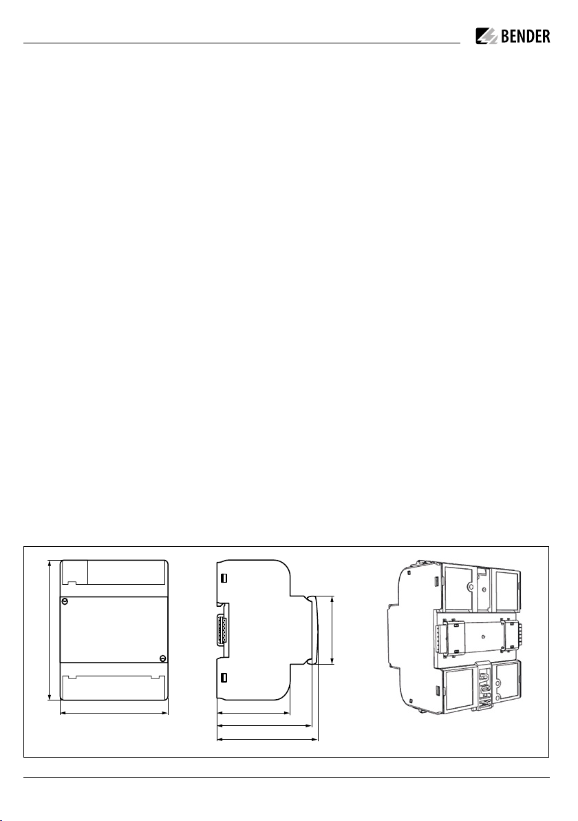
Maße und Rückansicht
93
71,7
48,5
62,9
66,9
45
93
71,7
48,5
62,9
66,9
45
Safety
Use of the device outside the Federal Republic of
Germany is regulated by the standards and regulations
applicable at the place of use. Within Europe, the
European standard EN 50110 applies.
I DanGer! Risk of death due to electric shock!
Touching live parts of the system carries the risk
of:
- an electric shock
- damage to the electrical installation
- destruction of the device
Before installing and connecting the device, make sure
that the installation has been de-energised. Observe the
rules for working on electrical installations.
Intended use
In the IOM441-S, alarm messages of a basic device can
be converted into switching commands for 12 relay out-
puts (N/O contacts). The communication between both
devices is carried out via the Bender backbone bus (BB
bus), which is mounted to the rear of the devices. The BB
bus also provides the supply voltage for the IOM441-S.
A software update of the IOM441-S can be carried out
via the BB bus. The parameters as well as switching
states are stored in the IOM441-S.
Some of the basic devices allow only one IOM441-S to
be connected to them (refer to the data sheet of the re-
spective basic device).
Any use other than that described in this manual is re-
garded as improper.
Dimensions and backview
IOM441-S/IOM441W-S
IOM441-S_D00300_04_M_DEEN / 03.2022 5
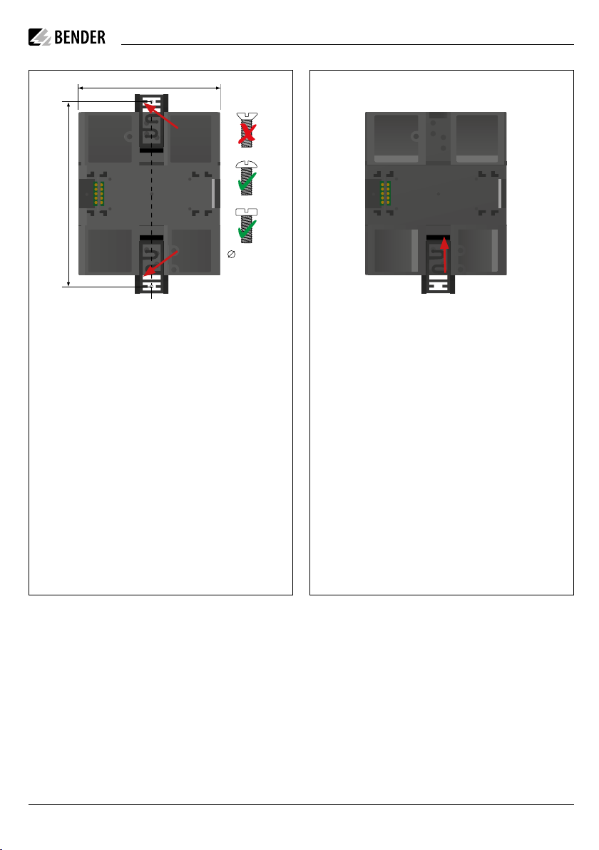
Schraubmontage | Screw mounting Montage auf Hutschiene | DIN rail mounting
99,0 mm
71,7 mm
M4
click!
DIN rail mounting
a. Fix mounting clip shown on picture above.
b. Attach the BB bus to the device. Please observe
the mounting instructions provided with the BB
bus.
c. Snap the IOM441-S on the DIN rail at some dis-
tance to the basic device.
d. Slide the devices towards each other until their BB
bus connectors have been interfaced.
Montage auf Hutschiene
a. Montageclips gemäß Abbildung anbringen.
BB-Bus am Gerät anbringen. Die BB-Bus
Montageanleitung beachten.
b. Das IOM441-S mit Abstand neben dem
Grundgerät auf der Hutschiene einrasten.
c. Beide Geräte zusammenschieben, so dass die
Kontakte des BB-Busses miteinander verbunden
sind.
Screw mounting
a. Fix the provided mounting clips shown above.
b. Slide the devices towards each other until their
BB bus connectors have been interfaced.
c. Drill the mounting holes for the M4 thread ac-
cording to the dimension diagram.
d. Fix the devices with two M4 screws.
Schraubmontage
a. Mitgelieferte Montageclips gemäß Abbildung
anbringen.
b. Beide Geräte zusammenschieben, so dass die
Kontakte des BB-Busses miteinander verbunden
sind.
c. Befestigungslöcher für M4-Gewinde gemäß dem
Maßbild bohren.
d. Geräte mit jeweils zwei M4-Schrauben befesti-
gen.
I Vorsicht! Sachschäden durch unsachgemäße
Demontage!
Wird eines der beiden verbundenen Geräte de-
montiert, ohne die Verbindung durch seitliches
Verschieben zu trennen, drohen Sachschäden an
dem BB-Bus und den damit verbundenen Geräten.
Geräte immer erst durch seitliches Verschieben
trennen.
I caution! Risk of damage to property due to in-
correct disassembly!
If one of the two connected devices is disassem-
bled without separating the connection by sliding
them to one side, the BB bus or the connected de-
vices may be damaged. Slide the devices to one
side in order to separate the connection.

6 IOM441-S_D00300_04_M_DEEN / 03.2022
IOM441-S/IOM441W-S
Anschluss
i
Das IOM441… immer nur rechts vom Grund-
gerät anschließen.
i
Für UL-Anwendungen:
Nur 60/75 °C-Kupferleitungen verwenden!
Verdrahten Sie das Gerät gemäß Anschlussbild.
Beachten Sie dabei die technischen Daten. Montieren
Sie nach dem Anschluss die mitgelieferten Klemmen-
abdeckungen!
Inbetriebnahme
Das Grundgerät versorgt das IOM441-S über den BB-
Bus. Versorgungsspannung des Grundgerätes einschal-
ten.
Die Parametrierung erfolgt über das Grundgerät.
Bedienung
Funktionen der LED (grün):
• LED an: IOM441(W)-S betriebsbereit
• LED aus: IOM441(W)-S nicht betriebsbereit
• LED blinkt: Gerätefehler
Werkseinstellung der Relaisausgänge
Für jeden der 12 Relaisausgänge im IOM441-S können
über die verschiedenen Grundgeräte jeweils verschie-
dene Parameter gesetzt werden.
Nähere Informationen zu den Einstellungsmöglich-
keiten erhalten Sie in den Handbüchern der jeweiligen
Grundgeräte.
Connection
i
Always connect the IOM441… only to the right
of the basic device.
i
For UL applications:
Use 60/75 °C copper lines only
Wire up the device according to the wiring diagram.
Please observe the technical data. After connecting the
device, install the enclosed terminal covers!
Commissioning
Switch on the supply voltage of the basic device. The
basic device supplies the IOM441-S via the BB bus.
Parameter setting is carried out via the basic device.
Operation
Functions of the LED (green):
• LED on: IOM441(W)-S ready for operation
• LED off: IOM441(W)-S not ready for operation
• LED flashes: device error
Factory settings of the relay outputs
Different parameters can be set via the differnet basic
devices for each of the 12 relay outputs in the IOM441-S.
Further information on the parameter settings can be
found in the manuals of the specific basic devices.
IOM441-S
ON
Ausgänge Relais/Outputs Relays
Ausgänge Relais/Outputs Relays

IOM441-S/IOM441W-S
IOM441-S_D00300_04_M_DEEN / 03.2022 7
Technische Daten
Isolationskoordination nach IEC 60664-1
Definitionen:
Versorgungskreis ........................................................................BB-Bus
Ausgangskreise............................Relaiskontakte (13, 14)…(123, 124)
Sichere Trennung (verstärkte Isolierung) zwischen ...............................
.................................................................(BB-Bus) – (Relaiskontakten)
Bemessungsspannung ..........................................................250 V
Überspannungskategorie............................................................III
Verschmutzungsgrad ...................................................................2
Bemessungs-Stoßspannung.................................................... 6 kV
Spannungs-/Stückprüfung nach IEC61010-1................. AC 3,51 kV
Basisisolierung zwischen ...................(Relaiskontakt) – (Relaiskontakt)
Bemessungsspannung ..........................................................250 V
Überspannungskategorie............................................................III
Verschmutzungsgrad ...................................................................2
Bemessungs-Stoßspannung.................................................... 4 kV
Spannungs-/Stückprüfung nach IEC61010-1................. AC 2,21 kV
Versorgungsspannung
Versorgungsspannung Us.......................................................... DC 24 V
Toleranz von Us................................................................................5 %
Eigenverbrauch.........................................................................< 1,7 W
LEDs
ON (Betriebs-LED)...........................................................................grün
Schaltglieder
Anzahl ................................................................................12 Schließer
Bemessungsbetriebsspannung.................................. AC 250 V/DC 30 V
Bemessungsbetriebsstrom................................................................5 A
Minimale Kontaktbelastbarkeit ................................1 mA bei ≥ DC 5 V
Umwelt/EMV
EMV .......................................................................IEC 61326-2-4
Umgebungstemperaturen:
Arbeitstemperatur .........................................................-25°C…+55°C
Transport .......................................................................-40°C…+85°C
Lagerung........................................................................-25°C…+70°C
Klimaklassen nach IEC 60721:
Ortsfester Einsatz (IEC 60721-3-3).................................................3K22
Transport (IEC 60721-3-2) .............................................................2K11
Langzeitlagerung Einsatz (IEC 60721-3-1).....................................1K22
Mechanische Beanspruchung nach IEC 60721:
Ortsfester Einsatz (IEC 60721-3-3)..................................................3M4
Transport (IEC 60721-3-2) ..............................................................2M4
Langzeitlagerung Einsatz (IEC 60721-3-1)....................................1M12
Einsatzhöhe ............................................................ ≤ 2 000 m über NN
Technical data
Insulation coordination according to IEC 60664-1
Definitions:
Supply circuit.............................................................................. BB bus
Output circuits .............................. relay contacts (13, 14)…(123, 124)
Protective separation (reinforced insulation) between..........................
....................................................................(BB bus) – (Relay contacts)
Rated voltage........................................................................ 250 V
Overvoltage category ................................................................. III
Pollution degree.......................................................................... 2
Rated impulse voltage ........................................................... 6 kV
Voltage/routine test acc. to IEC61010-1........................ AC 3.51 kV
Basic insulation between.....................(relay contact) – (relay contact)
Rated voltage........................................................................ 250 V
Overvoltage category ................................................................. III
Pollution degree.......................................................................... 2
Rated impulse voltage ............................................................ 4 kV
Voltage/routine test acc. to IEC61010-1........................ AC 2.21 kV
Supply voltage
Supply voltage Us...................................................................... DC 24 V
Tolerance of Us.................................................................................5 %
Power consumption..................................................................< 1.7 W
LEDs
ON (operation LED).......................................................................green
Switching elements
Number......................................................................... 12 N/O contacts
Rated operational voltage ......................................... AC 250 V/DC 30 V
Rated operational current.................................................................5 A
Minimum contact rating.............................................1 mA at ≥ DC 5 V
Environment/EMC
EMC..................................................................................IEC 61326-2-4
Environment temperatures:
Operating temperature .................................................-25°C…+55°C
Transport .......................................................................-40°C…+85°C
Storage ..........................................................................-25°C…+70°C
Classification of climatic conditions acc. to IEC 60721:
Stationary use (IEC 60721-3-3)...................................................... 3K22
Transport (IEC 60721-3-2) .............................................................2K11
Long-term storage (IEC 60721-3-1)..............................................1K22
Classification of mechanical conditions acc. to IEC 60721:
Stationary use (IEC 60721-3-3)..................................................... 3M11
Transport (IEC 60721-3-2) ..............................................................2M4
Long-term storage (IEC 60721-3-1).............................................. 1M12
Range of use.............................................................. ≤ 2,000 m AMSL

IOM441-S/IOM441W-S
Alle Rechte vorbehalten.
Nachdruck und Vervielfältigung
nur mit Genehmigung des Herausgebers.
Bender GmbH & Co. KG
Postfach 1161 • 35301 Grünberg • Deutschland
Londorfer Str. 65 • 35305 Grünberg • Deutschland
Tel.: +49 6401 807-0 • Fax: +49 6401 807-259
All rights reserved.
Reprinting and duplicating
only with permission of the publisher.
Bender GmbH & Co. KG
PO Box 1161 • 35301 Grünberg • Germany
Londorfer Str. 65 • 35305 Grünberg • Germany
Tel.: +49 6401 807-0 • Fax: +49 6401 807-259
IOM441-S_D00300_04_M_DEEN / 03.2022/ pdf / © Bender GmbH & Co. KG, Germany – Subject to change! The specied standards take into account the edition valid until 03/2022 unless otherwise indicated.
Connection
Connection type......................................pluggable push-wire terminal
Conductor sizes....................................................................AWG 24-12
Stripping length......................................................................... 10 mm
rigid/flexible...................................................................0.2…2.5 mm²
flexible with ferrules, with/without plastic sleeve........0.25…2.5 mm²
Multiple conductor, flexible with TWIN ferrule
with plastic sleeve ......................................................... 0.5…1.5 mm²
Other
Operating mode................................................... continuous operation
Degree of protection internal components ....................................IP40
Degree of protection terminals ......................................................IP20
DIN rail mounting acc. to........................................................IEC 60715
Screw fixing ............................................... 2 x M4 with mounting clip
Enclosure material.......................................................... polycarbonate
Flammability class ...................................................................UL 94V-0
Dimensions (W x H x D).......................................................72 x 93 x 63
Documentation number.............................................................D00300
Weight............................................................................. approx. 180 g
Device feature „W“
Devices with the suffix „W“ feature increased shock and vibration resis-
tance. The electronics is covered with a special varnish to provide increa-
sed protection against mechanical stress and moisture.
Environment temperatures:
Operating temperature.................................................... -40…+70 °C
Transport ......................................................................... -40…+85 °C
Storage ............................................................................ -25…+70 °C
Classification of climatic conditions acc. to IEC 60721:
Stationary use (IEC 60721-3-3)...................................................... 3K23
Classification of mechanical conditions acc. to IEC 60721:
Stationary use (IEC 60721-3-3)..................................................... 3M12
Anschluss
Anschlussart..................................................... steckbare Federklemme
Leitergrößen........................................................................AWG 24-12
Abisolierlänge............................................................................ 10 mm
starr/flexibel ...................................................................0,2…2,5 mm²
flexibel mit Aderendhülse mit/ohne Kunststoffhülse ...0,25…2,5 mm²
Mehrleiter flexibel mit TWIN-Aderendhülse
mit Kunststoffhülse........................................................ 0,5…1,5 mm²
Sonstiges
Betriebsart........................................................................ Dauerbetrieb
Schutzart Einbauten........................................................................IP40
Schutzart Klemmen ........................................................................IP20
Schnellbefestigung auf Hutprofilschiene................................IEC 60715
Schraubbefestigung..........................................2 x M4 mit Montageclip
Gehäusematerial............................................................... Polycarbonat
Entflammbarkeitsklasse...........................................................UL 94V-0
Maße (B x H x T)..................................................................72 x 93 x 63
Dokumentationsnummer...........................................................D00300
Gewicht....................................................................................ca. 180 g
Geräteausführung „W“
Die Geräte mit der Endung „W“ entsprechen erhöhter Schock und Rüttel-
festigkeit. Durch eine besondere Lackierung der Elektronik wird ein höhe-
rer Schutz gegen mechanische Belastung und gegen Feuchtigkeit erreicht.
Umgebungstemperaturen:
Arbeitstemperatur ........................................................... -40…+70 °C
Transport ......................................................................... -40…+85 °C
Langzeitlagerung............................................................. -25…+70 °C
Klimaklassen nach IEC 60721:
Ortsfester Einsatz (IEC 60721-3-3).................................................3K23
Mechanische Beanspruchung nach IEC 60721:
Ortsfester Einsatz (IEC 60721-3-3)................................................3M12
Other manuals for IOM441-S
2
This manual suits for next models
3
Table of contents
Other Bender Relay manuals

Bender
Bender VME421H User manual

Bender
Bender IOM441-S User manual

Bender
Bender LINETRAXX VMD258 User manual

Bender
Bender IOM441-S User manual

Bender
Bender cme420 User manual

Bender
Bender EDS44 L-CN Series User manual

Bender
Bender cme420 User manual

Bender
Bender RCM470LY User manual

Bender
Bender CMD420 User manual

Bender
Bender LINETRAXX VMD461 User manual


