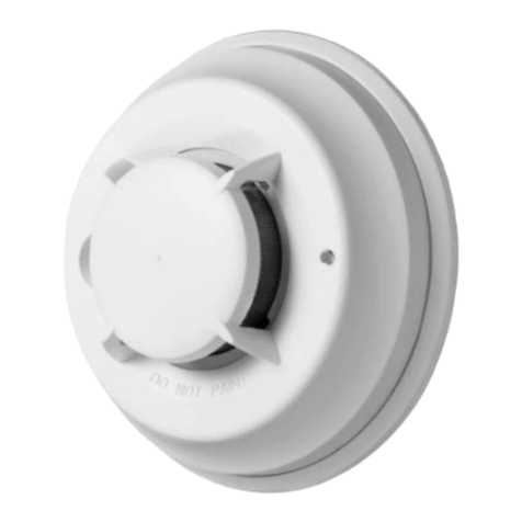
Gira 0496 06 Guide

GIRA
Info Smoke detector plus / VdS
Instructions for Installation
Smoke detector plus / VdS 02/02 Seite: 1 von 6
Smoke detector plus / VdS with relay module
pure white Art. Nr.: 0496 06
alu 0496 07
Smoke detector plus / VdS with radio transmitter module
pure white Art. Nr.: 0496 08
alu 0496 09
Product features
•Battery-operated stand-alone Home Smoke Detector working on photoelectric principle.
•Automatic self-test for smoke-sensing electronics, therefore extremely reliable and immune to
interference.
•Option of operating as a wireless network with radio transmitter modules and a wireless alarm unit
(available as extras).
•Loud pulsating warning tone if smoke detected, approx. 85 dB (A).
•Battery low-power monitor (LED and short beeps at intervals) warns that battery voltage is
growing weaker, for up to about 30 days.
•Contamination/fault warning function with LED and short beep.
•Option of operating as a wired network with relay modules (available as extras). Up to 40 smoke
detectors can be linked together. If one smoke detector identifies a fire, the alarm is relayed all the
other smoke detectors in the network.
•Integrated test button: if the smoke detector emits its warning tone when the test button is
pressed, it is in good working order.
•Simple mechanical safeguard prevents smoke detector clicking into place in its base if no battery
is fitted.
•Damage to the detector is not possible if the battery is installed with the wrong polarity.
Operating principle
The smoke detector is an early warning device for smouldering fires as well as flaming fires that
develop smoke. It operates on the proven light scatter principle. lnside the sensing chamber a light
source and a light sensor are arranged so that light normally does not fall on the sensor. It is only
when airborne particles enter the chamber that light is scattered onto the sensor (Tyndall effect) to
produce an electrical signal. This design means that no radioactive source is required. Smouldering
fires in particular are quickly identified by the smoke detector and the alarm given.
If smoke enters the sensing chamber, the built-in sounder is triggered. A logic circuit to eliminate false
alarms delays the alarm signal and resetting by up to 30 seconds.
This product has been approved by the Schadenverhütung GmbH in Cologne (VdS). Only security
products meeting the high quality demands of the prEN 12239 receive this approval.
Important test criteria are:
•reliable smoke detection characteristics
•good smoke entry
•immunity to electrostatically discharge
•functional check and battery presence control
•Test button

GIRA
Info Smoke detector plus / VdS
Instructions for Installation
Smoke detector plus / VdS 02/02 Seite: 2 von 6
Choice of location
The minimum protection is one smoke detector on every
floor (hall or landing area) and in every child’s bedroom.
It is better, however, to have a smoke detector in every
room, apart from the kitchen and bathroom, where steam
can cause false alarms.
Fig.1
Fig.2
The smoke detector must be fixed to the ceiling as near to the
centre of the room as possible. One detector can monitor a room
with a maximum floor area of 60 m² with a ceiling height of up to
6 m. In hallways and narrow corridors (up to 3 m wide) the
detector monitors a distance of up to 7.5 m in each direction. A
gap of at least 0.5 m must be maintained from walls and fixtures.
You should therefore install:
•as an absolute necessity one smoke detector in the hallway
(to monitor the escape route) between living and sleeping
areas
•for optimum protection one detector in every living room and
every bedroom
•in multistorey buildings at least one detector on each landing
•in converted lofts one detector above the staircase
Installation on the ceilings of boat cabins or caravans is also
possible. When travelling, simply take the smoke detector with
you into your hotel room.
Unsuitable locations
Never install the smoke detector
•near to ventilation ducting or strong draughts
•directly in the apex of pitched roofs (a minimum distance of 30 cm from the apex must be
maintained)
•in rooms where there is a lot of steam, dust or smoke under normal conditions (workshops,
bathrooms, laundry rooms, for example)
•in rooms where the temperature rises above +40 °C or falls below +5 °C
•in the vicinity of fluorescent luminaires.
Installation and putting into service
Fig.3
The home smoke detector is installed as follows:
•Remove the smoke detector from its base by turning it
anticlockwise.
•Screw the base to the ceiling using the fixing materials
provided (see Fig. 3 for dimensions).
•
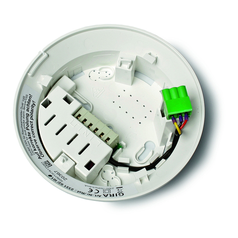
A
ttach the 9 V rectangular battery to the connector and insert
it into the battery holder (1).
•Insert the smoke detector into the base, without using force,
and turn it gently clockwise until it clicks into place.
Note: If no battery is fitted, the smoke detector will not click
into place!
•Finally verify the good working order of the smoke detector
by pressing ist test button.

GIRA
Info Smoke detector plus / VdS
Instructions for Installation
Smoke detector plus / VdS 02/02 Seite: 3 von 6
Networking home smoke detectors
Fig.4
A relay module, available as an optional extra, is required for
networking home smoke detectors. Up to 40 smoke alarms
(relay type) can be networked using a twisted pair of wires
(e.g.telephone cable). For installation see figure 5. A
maximum of 500 metres of a 0.6 mm diameter copper cable
can be used. In addition, external signalling devices such as
sounders or alarm beacons can also be connected.
Note: If a device with an inductive load is connected, a free-
wheeling diode (type 1N4007) must be included in the circuit.
In doubtful cases please consult your local specialist dealer.
Fig.5

GIRA
Info Smoke detector plus / VdS
Instructions for Installation
Smoke detector plus / VdS 02/02 Seite: 4 von 6
The home smoke detector is installed as follows:
•Remove the home smoke detector (Fig.3, B) from its base (A) by turning it anticlockwise.
•Open the required cable entry knockouts, then fix the base to the ceiling using the fasteners
supplied with each unit (see Fig.4 for dimensions).
•Run the interconnecting cables and insert the ends into the base through the open knockouts.
Make sure there is enough slack cable (about 10 cm minimum) inside the base for easy
connection and disconnection of the relay on the home smoke detector.
•Feed the two-core cable through the strain-relief grip provided (Fig.5) before connecting it to the
relay module as shown on the wiring diagram. Then carefully plug the relay module into the seat
provided for it (Fig.6, 1).
•Attach the 9 V rectangular battery to the connector (4) and insert it into the battery holder (1).
•Insert the home smoke detector into the base, without using force, and turn it gently clockwise
until it clicks into place.
Note: If no battery is fitted, the home smoke detector will not click into place!
•Finally verify the good working order of the home smoke detector by pressing its test button (4).
•When one test button is pressed, all the home smoke detectors linked together in the network
must sound the alarm. If a networked home smoke detector does not activate the alarm, this can
be for three reasons: (a) open circuit/disrupted network, (b) battery incorrectly connected,
(c) battery fully discharged. Check these three points.
Fitting relay and radio transmitter modules (optional extras)
Turn the home smoke detector anticlockwise to remove it from its base. Holding the radio transmitter
module at its edges, carefully insert it into the seat provided for it (Fig.6).
Fig.6 Relay module Radio transmitter module

GIRA
Info Smoke detector plus / VdS
Instructions for Installation
Smoke detector plus / VdS 02/02 Seite: 5 von 6
Operating and warning signals
The home smoke detector has a logic circuit to eliminate false alarms, the alarm signal being delayed
by up to 30 seconds. When the sensing chamber is free of smoke again after an alarm, the home
smoke detector automatically resets itself into a state of readiness within 30 seconds.
Signal Significance
Loud alarm tone at intervals. Red LED flashes. Local smoke alarm
Loud alarm tone at intervals. Red LED does not
flash. (only with networked home smoke detectors
with relays).
External smoke alarm: the detector is repeating
an alarm from another home smoke detector.
Brief beep tone at one-minute intervals,
the red LED simultaneously flashing briefly
(for up to about 30 days).
Battery low-power indicator.
The battery must be replaced.
Brief beep tone at one-minute intervals,
the red LED flashing out of phase.
Smoke sensing system fault
(replace home smoke detector).
Red LED flashes briefly at intervals of
about 40 seconds
Automatic self-test, normal operating condition.
Safety instructions
•The home smoke detector must not be painted.
•The loud alarm signal can damage hearing.
We recommend that when you carry out the manual test, a minimum distance of 40 cm is
maintained between the home smoke detector and your ear. Do not prolong the test for longer
than 10 seconds.
•A warning light or a vibrating pillow must be installed for people with hearing defects. These can
be activated by a home smoke detector with a relay.
•Home smoke detectors do not extinguish fires. If an alarm occurs, the source of the fire must be
located and, if necessary, the fire brigade alerted.
•The home smoke detector only works when the battery is in good working order and correctly
installed.
Rechargeable batteries or AC adapters must not be used, as they can disturb the functioning of
the detector or cause its premature failure.
•The home smoke detector responds to the smoke from a fire, not to the flame itself.
•The home smoke detector only monitors a defined area in its vicinity and will not necessarily
monitor another room or another floor (see also “Choice of location ”).
Therefore install a sufficient number of home smoke detectors to ensure optimum protection.
•The home smoke detector should be audible in the entire living area. If necessary, install
additional sounders, e.g. a klaxon.
•It is possible that people under the influence of alcohol or drugs may not be woken up by the
alarm signal.
Maintenance and care
To ensure proper functioning of the home smoke detector, please pay attention to the following points:
•If the home smoke detector emits a short beep at intervals of one minute and the LED flashes
simultaneously, the battery must be replaced. Only use 9 V rectangular type ICE6 CR61 batteries.
Caution!
–Do not use rechargeable batteries.
–Do not change the battery when the detector is in the alarm condition.
•Replace home smoke detectors after about 10 years of service.

GIRA
Info Smoke detector plus / VdS
Instructions for Installation
Smoke detector plus / VdS 02/02 Seite: 6 von 6
Monthly
•Press the test button;
–If it emits the warning tone, the home smoke detector is in good working order.
–If the warning tone is not emitted, please check the battery connection or replace the battery
with a new one. If the test results are then still negative, the home smoke detector must be
replaced.
6-monthly
•Remove the home smoke detector from its base and wipe it with a damp cloth.
•Reinsert the home smoke detector in its base and turn it clockwise until it clicks into place.
Technical data
Sensitivity to prEN 12239 (95)
Operating voltage 9 V DC
Current consumption
Quiescent current typical
Alarm current (type without relay) max.25 mA
Alarm current (relay type) max.50 mA
Relay module NO contacts, volt-free
Switched voltage max. 30 V DC
Switched current max. 1 A
Battery rectangular battery
Battery type ICE6 LR 61, 9 V
Battery low power signal 1/min, 30 days
Alarm indicator LED, red
Sounder 85 dB (A)
Ingress protection IP 42
Ambient service temperature + 5 to + 40 °C
Storage temperature - 5 to + 60 °C
VdS approval see nameplate on smoke detector
Weight (without battery) 130 g
Acceptance of guarantee
We accept the guarantee in accordance with the corresponding legal provisions.
Please return the unit postage paid to our central service department giving a brief description
of the fault:
Gira
Giersiepen GmbH & Co. KG
Service Center
Dahlienstrasse 12
D-42477 Radevormwald
The CE sign is a free trade sign addressed exclusively to the authorities and does not include
any warranty of any properties.
Gira
Giersiepen GmbH & Co. KG
Postfach 1220
D-42461 Radevormwald
Telefon: +49 / 21 95 / 602 - 0
Telefax: +49 / 21 95 / 602 - 339
Internet: www.gira.de
This manual suits for next models
3
Table of contents
Other Gira Smoke Alarm manuals

