Gira 1258 00 User manual

Installation and
Operating Instructions
Built-In Loudspeaker
1258 00

2
Device description
With the built-in loudspeaker, the Gira Door
Communication System is integrated in let-
terbox systems, speech compartments, door
side installations or front panels. The built-in
loudspeaker assumes the function of a door
station. It has two mounting openings which
are matched to the mounting systems of
common installation solutions.
Up to 8 mechanical bell buttons can be con-
nected to the built-in loudspeaker. Addi-
tional bell buttons can be connected via add-
on modules. It is possible to connect up to
5 add-on modules with 12 bell buttons each.
With these door communication systems
with up to 70 audio devices can be realised,
e.g.
1 Audio control device
1 Built-in speaker with
5 Add-on modules
68 Surface-mounted, hands-free feature
home stations
iNumber of devices
The Gira door communication system is
designed for the following numbers of
devices:
Audio: 70 devices, Video: 20 devices.
3
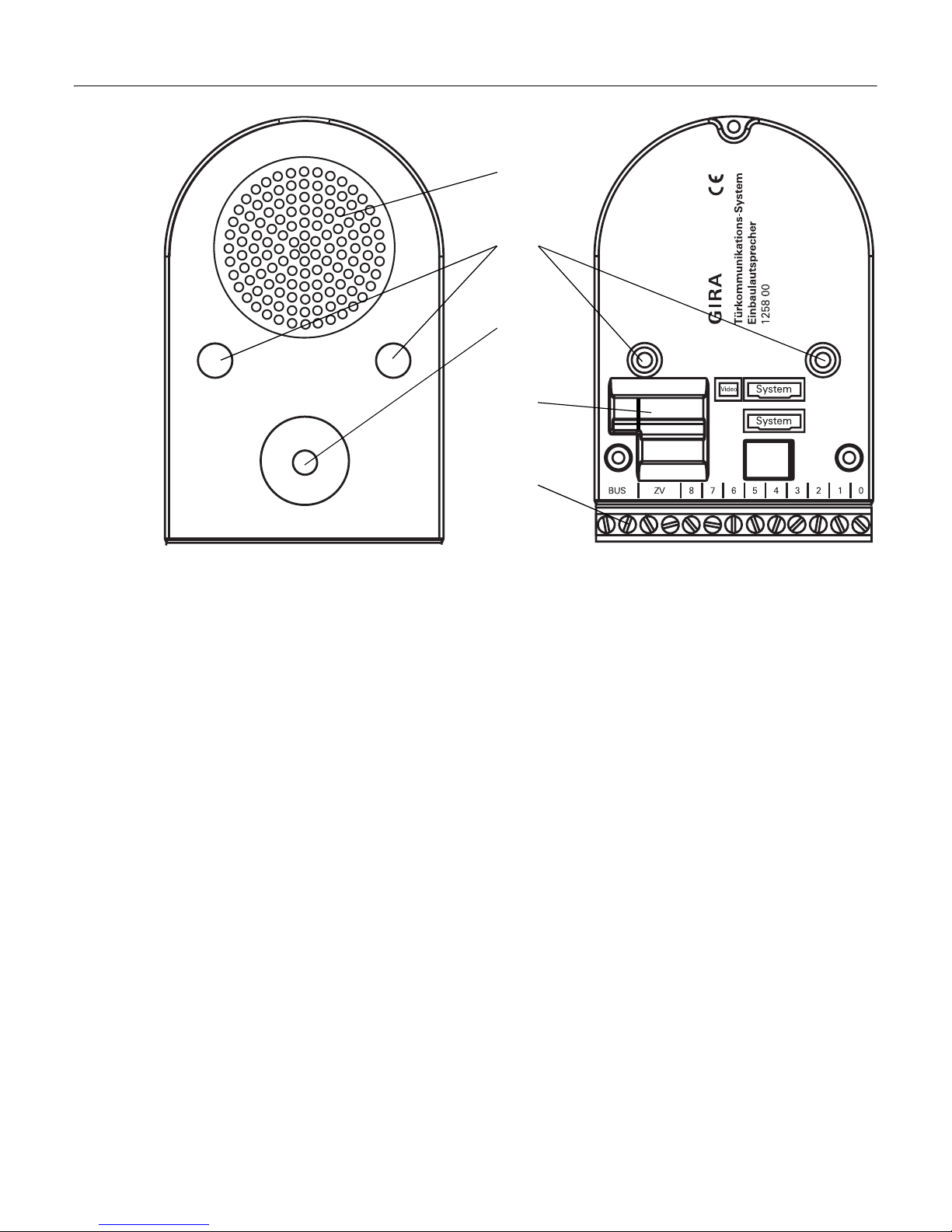
Device presentation
Front
1 Loudspeaker
2 Mounting opening
3 Microphone
Back
4Interfaces
System: Connection for add-on module
or other system components
Video: Connection of the UP colour
camera
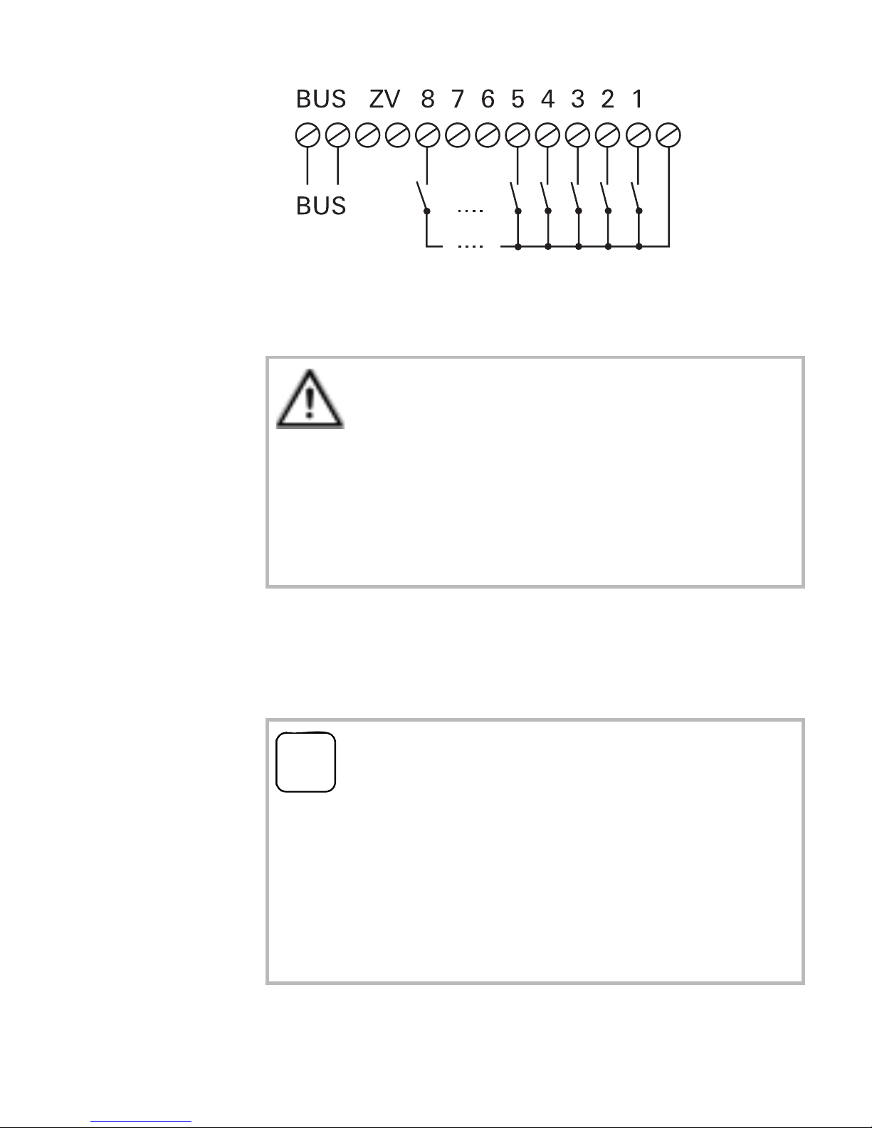
5 Terminal strip
BUS: Connection to the 2-wire bus
ZV: Supply of UP colour camera etc.
0: Common earth for bell buttons
1 - 8: Connection for bell buttons
1
2
3
4
5

4
Mounting
The built-in loudspeaker in mounted behind
the speech cover plate of the existing sys-
tem. Depending on the design, this is carried
out directly on the front panel or via an
installation carrier.
Attention
Installation and mounting of electrical
devices may only be carried out by a quali-
fied electrician.

5
Use only the screws provided to mount the
built-in loudspeaker.
When positioning the built-in loudspeaker,
make sure that both the microphone and the
loudspeaker are mounted in front of the
sound openings. Here the position of the
microphone should be given a higher prior-
ity.
The best speech quality is achieved when a
separating bar is located between the loud-
speaker and the microphone.
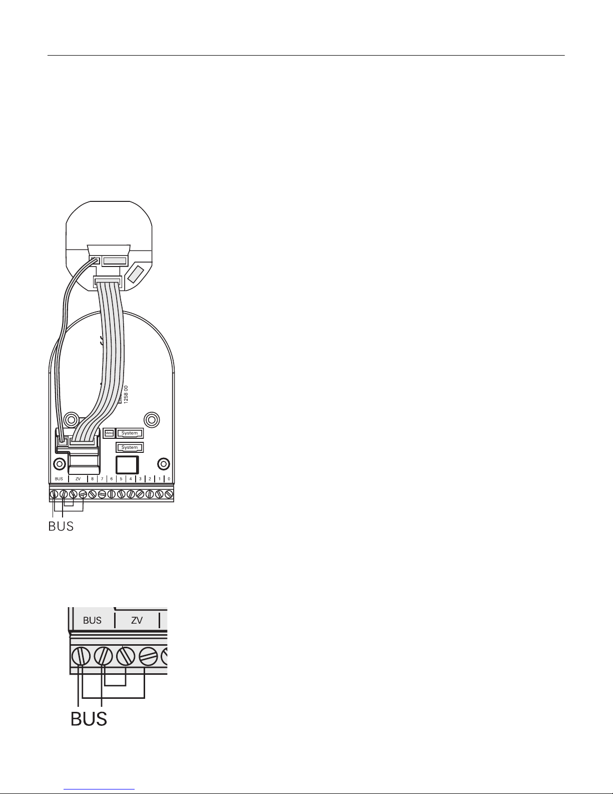
Connection
1. Connect the 2-wire bus to the BUS termi-
nals.
2. If necessary, fit jumpers between the BUS
and ZV terminals. This is necessary when
illuminated system components or a col-
our camera are to be operated on the
built-in loudspeaker.
6
3. Connect the bell buttons. The maximum
cable length is 2 m.
4. If necessary, connect additional compo-
nents from the door communication sys-
tem via the "System" or "Video" slots.
Do not connect "0" terminal
When using an add-on module, the "0" ter-
minal of the built-in loudspeaker may not
be connected to the "0" terminal of the add-
on module.
iIllumination of bell buttons
The illumination of the bell buttons cannot
be supplied via the bus system of the door
communication system.
Use an additional power supply for the bell
button illumination.
0
7
Connecting door communication components
Due to the full compatibility of the built-in
loudspeaker to the door communication sys-
tem, flush-mounted inserts, such as a colour
camera, info module or call buttons, can also
be connected.
Colour camera
1. Connect the flush-mounted insert of the
colour camera with the built-in speaker
using the 2-pole video connection cable
and the 6-pole audio connection cable.
2. Fit jumpers between the BUS and ZV ter-
minals on the built-in
loudspeaker.
Info module, call button
1. Connect the flush-mounted insert of the
device to the built-in loudspeaker using
the 6-pole audio connection cable.
2. To activate the illumination of the info
module or the call button, fit jumpers
between the BUS and ZV terminals on the
built-in loudspeaker.
8
Start-up
Once you have installed all of the devices
(built-in loudspeaker, home station, control
device etc.), you can put the door communi-
cation system into operation.
Commissioning is described in the system
manual included with the control device.
iNote
When commissioning large systems,
please note that a maximum of 20 bell but-
tons can be temporarily stored per work
step. If more than 20 bell buttons are
installed, at first the initial 20 bell buttons
must be assigned to the home stations.
Then the next 20 or the remaining bell but-
tons are assigned.

9
Operation
Volume setting
The volume can be set separately at each
door station.
The volume setting must be made by two
people.
1. Start programming mode at the control
device by pressing the "System progr."
button for 3 seconds until the yellow LED
next to the button starts flashing.
2. Briefly press a previously assigned bell
button at the door station.
3. The second person accepts the door call
at the home station (via receiver or
speech button) and starts speaking.
4. Briefly press the bell button at the door
station again.
✓The volume changes when the button is
pressed during the voice connection.
There are four volume levels in total.
The next-highest volume is set with each
button press.
When the loudest volume level is reached,
the next button press sets the quietest
volume level.

10
5. End the voice connection.
The most recently set volume level is
saved in the door station.
6. Exit programming mode at the control
device by briefly pressing the "System
progr." button.
11
Acceptance of guarantee
We accept the guarantee in accordance with
the corresponding legal provisions.
Please return the unit postage paid to our
central service department giving a brief
description of the fault.
Gira
Giersiepen GmbH & Co. KG
Service Center
Dahlienstraße 12
42477 Radevormwald
Germany
The CE sign is a free trade sign
addressed exclusively to the
authorities and does not include
any warranty of any properties.

Gira
Giersiepen GmbH & Co. KG
P.O. Box 1220
42461 Radevormwald
Tel +49 21 95- 602-0
Fax +49 21 95- 602-339
www.gira.com
Other Gira Speakers manuals


