Girard Systems 98GC274B User manual

2
\\
Girard Systems awnings may be operated in light wind and rain
conditions. When periods of heavy rain and or high wind are expected
the awning must be closed. Never leave the awning open and
unattended.
Damage caused by wind and rain is not covered by warranty.
All awnings must be closed prior to moving the vehicle for any reason.
As an extra safety precaution a visual check that every awning is fully
closed is required.
Damage caused by failure to comply with these instructions is
not covered by warranty.
Before using your awning, ensure that the area into which the awning
will be deployed is free of obstructions (Trees, walls, pillars, posts,
other vehicles etc.)
Damage caused by collisions with any of the above or similar is
not covered by warranty.
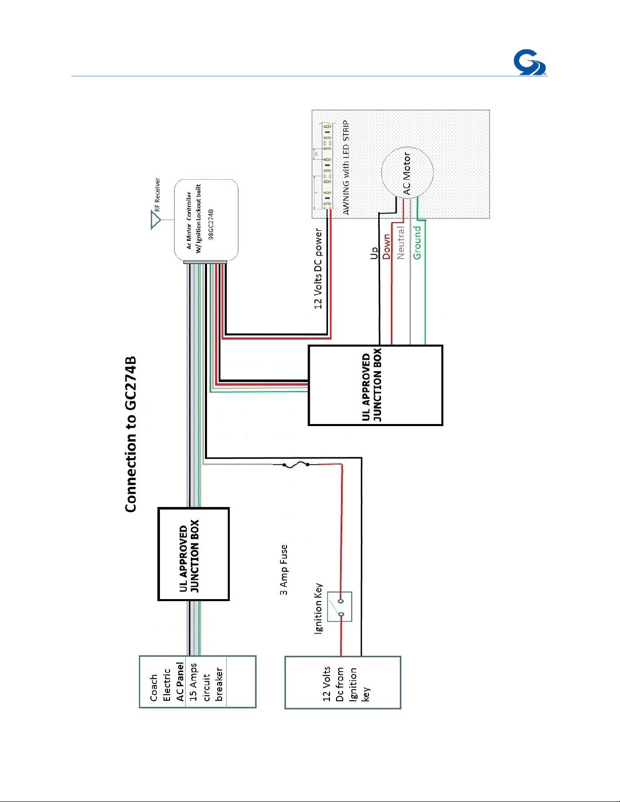
Before using your awning make sure that all of your electrical circuits
are operating correctly. Recreational Vehicles can generate AC power
from three separate sources. The electrical system transfer switch in
your vehicle will select power for the awning as follows:
Shore Power –if connected;
Generator Power –if the generator is running;
Inverter Power –batteries must be charged for inverter operation.
Girard Systems awnings are supplied with an electric motor appropriate to the
product.

3
CONTENTS
98GC274B Product description ………………………………………………………………………4
Specification ……………………………………………………………………………………………….. 5
Wiring Diagram …………………………………………………………………………………………… 7
Set up and Programming ..……………………………………………………………………………. 8
Change Motor Direction.………….……………………………………………………………………. 8
Cancel a remote or all remote from GC274B……………………………………………………. 9
Multichannel Handset remote ………………………………………………………………………. 10
Programming the GC274B to a Remote handset 98GC2762B ………………….…….….11
Multichannel Wall Switch 98GC2763B………………………………………………………….... 15
Programming the GC274B to a Wall Switch 98GC2763B ………………….……………… 16
Programming to a Motion Sensor …………………………………………………………………. 18
THE G–LINK SYSTEM
The G-Link motors and control modules provided by Girard Systems communicate by
use of RF signals on a frequency of 433.92 MHZ. This eliminates the need for wiring
and the drilling of holes in the vehicle. These components must be electronically
matched, programmed or paired before use. This is usually done at the Girard Systems
factory. Should the need arise for the user to pair a device with the motor controller
they must refer to the appropriate manual for the devices applicable to their particular
installation.

4
98GC274B PRODUCT DESCRIPTION
AC Motor Controller with LED (12V DC) control plus Ignition retract and lockout.
Fig.1
•This module is designed to control a single Standard 110v AC Motor up to 8
Amps and can be remotely operated with any paired G-Link handset or wall
switch.
•The controller will receive signals from a distance of more than 500ft in open air
and more than 100ft in the presence of obstructions. The RF transmission
frequency is 433.92MHZ.
•The GC274B may be programmed with up to 20 compatible remote modules. If
an additional module is programmed it will replace the most recently
programmed module. The previous 19 modules will remain unchanged.
•The command to retract the awning can be initiated by turning on the ignition
switch or by releasing the parking brake depending upon how it is installed.
•This module will cause the awning to retract when the vehicle prepares to move
and then remove power to the awning so that it cannot be redeployed while the
vehicle is in motion.
OUT
STOP
IN

5
Fig.2
1) 110v AC Power supply from vehicle power distribution board.
2) Output to awning motor control.
3) Initiate retract signal from vehicle ignition or parking brake.
4) 12v DC to LED lighting.
Specifications
Power: 110VAC / 60Hz
AC Input: White = Neutral / Black = Live / Green = Earth
To the Motor: White = Neutral / Red = Direction 1 / Black = Direction 2 / Green =
Earth
Ambient T: 0 - 130°F
Installation
A circuit breaker protected 15A/115v AC power outlet is required form the Vehicles
power distribution panel as shown in the diagram below.
1. Install a UL approved 110VAC junction box in which to make the electrical
connections.
1
2
3
4

6
2. Route the Awning’s Motor cable to this location and make the connections to the
GC274B in accordance with NEC requirements.
3. Mount the GC274B on the wall using the screws and tape provided.

7

8
SETUP AND PROGRAMMING
1. Change motor direction
a. Supply power to GC274B
b. Simultaneously press the LEFT and RIGHT buttons of the GC274B for at least
6 seconds. The Green LED will illuminate and then blink a few times. When the
Green LED extinguishes, the operation is complete.
Fig.3
Note; when carrying out this part of the procedure each step must be
executed within 10 seconds of the previous one or the module will revert to
factory settings. It is highly recommended that you read and understand the
following sequence before attempting to execute it.
2. Programming the GC274B to a Remote handset or Wall switch
a. Supply power to the GC274B
b. Press and hold the MIDDLE and RIGHT buttons on the GC274 (Fig 3) for
about 3 seconds until the Green LED starts to flash.
c. Press STOP (Fig. 1): The Green LED will stop blinking and remain illuminated.
d. Press the IN button on the REMOTE DEVICE being programmed. The Green
LED on the motor controller will extinguish.
CHANGE MOTOR DIRECTION
PROGRAM MODE

9
3. Cancel one Remote from the GC274B
a. Supply power to the GC274B
b. Press and hold the MIDDLE and RIGHT buttons on the GC274 (Fig 3) for
about 3 seconds until the Green LED starts to flash.
c. Press STOP (Fig. 1): The Green LED will stop blinking and remain illuminated.
d. Press the OUT button on the REMOTE DEVICE being cancelled. The Green
LED will extinguish.
4. Cancel all of the Remotes from the GC274B
a. Supply power to GC274B
b. Simultaneously press the STOP and LEFT button of the GC274 for at least 6
seconds: The Green LED will first illuminate and then blink a few times. When
the Green LED extinguishes the operation has been completed.

10
98GC2762B
MULTI CHANNEL REMOTE HANDSET
PRODUCT DESCRIPTION
The 98GC2762 remote handset is a Multi-channel RF transmitter, powered by a single 3v
Lithium battery (CR2450) designed to control up to 15 awnings and operate the LED
lighting strips by means of a multi-functional circular control pad. As shown in Fig.1 below.

11
Fig.4
Programming a Remote handset to 98GC274B
a. Supply power to the GC274B
b. Press and hold the MIDDLE and RIGHT buttons on the GC274 (Fig 3) for
about 3 seconds until the Green LED starts to flash.
c. Press STOP (Fig. 1): The Green LED will stop blinking and remain illuminated.
d. Press the IN button (Fig.4) on the REMOTE DEVICE being programmed. The
Green LED on the motor controller will extinguish.

12
To find the battery turn the remote handset over and slide the cover down;
•The Battery compartment, (into which a single CR2450 3v Lithium battery should
be inserted as shown, Fig.5)
•The P2 button (used when pairing the device to some other G-Link Modules)
Fig.5

13
Magnetic Holder.- This new G link transmitter was designed with a magnetic plate
holder to keep it in place and make it more user friendly. See Fig 6 below.
Fig.6

14
To install the plate holder to the coach it is necessary to remove the front cover to have
access to the mounting holes, see Fig.7 below.
Fig.7

15
98GC2763B
MULTI CHANNEL WALL SWITCH
PRODUCT DESCRIPTION
The 98GC2763B is a Multichannel RF transmitter, powered by two 3v Lithium batteries
(CR2430) designed to control up to 20 awnings. See figure 8 for description of each
pad.

16
Fig.8
Programming a Wall Switch to 98GC274B
a. Supply power to the GC274B
b. Press and hold the MIDDLE and RIGHT buttons on the GC274 (Fig 3) for
about 3 seconds until the Green LED starts to flash.
c. Press STOP (Fig. 1): The Green LED will stop blinking and remain illuminated.
d. Press the IN button (Fig.8) on the REMOTE DEVICE being programmed. The
Green LED on the motor controller will extinguish.

17
To find the batteries turn the wall switch over and using a small flate screw driver pull
the cover off, the cover has the word “open” on the right bottom corner, see Fig.9
below.
•The Battery compartment, (into which three CR2430 3v Lithium battery should
be inserted as shown)
Fig.9
Magnetic Holder.- This new G link transmitter was designed with a magnetic plate
holder to keep it in place and make it more user friendly. See Fig 10 below.
Fig.10

18
98GC779G
REMOTE MOTION SENSOR
Programming the GC274B to a Motion Sensor (98GC779G)
This procedure will require opening the motion sensor module by following the
directions below;
a. Remove the 2 small cross head screws which secure the motion sensor to the
mounting bracket. See Fig.11.
Fig.11
b. Detach the motion sensor from the bracket, the base plate is magnetized so will
need to be gently lifted off. Then turn it over. See Fig.12

19
Fig.12
c. Remove the 4 cross head screws holding the module together. Remove the back
plate and silicone insert. See Fig.13.
Fig.13
Base plate
Magnet
Silicone Insert

20
d. Turn the base plate over (Magnet down). Then place the motion sensor on top of
it so that the magnet is aligned with the reed switch. See fig.14. If this is not
done the default program cannot be changed.
Fig.14
Note; when carrying out this part of the procedure each step must be
executed within 10 seconds of the previous one or the module will revert to
factory settings. It is highly recommended that you read and understand the
following sequence before attempting to execute it.
a. Set the Motion sensor Adjustment Dial to level 5. (See Fig.14)
b. To initiate the programming sequence, power to the motor controller must be
disconnected for at least 10 seconds then reconnected.
c. Connect the GC779G Motion sensor to a 12volt DC circuit. At this point the
Purple LED will illuminate and then begin to blink. If it does not, the module is
not receiving the correct power. Ensure that the magnet and reed switch are
aligned and verify the electrical connection before proceeding.
Reed Switch
LED
Sensitivity Dial
Program Button
Other manuals for 98GC274B
1
Table of contents
Other Girard Systems Controllers manuals