GL McGAVIN MODIEWARK DC50 User manual

2
Warning
High voltage testing should only be carried out by trained personnel.
Do not hold this instrument in your hand when testing uninsulated voltages
above 300VDC.
Fiberglass Operating sticks must be used.
--------------
This device is for indication only and should only be used by trained
personnel on the safe operations of the device.
Warning. the indicator will not indicate when conductors are in a high
field area, close proximity to one another, in a metal case enclosed
spaces or in armored metal screen cable.
The DC field can be compromised and the device will not indicate, it is
recommended from the manufacturer if adequate space, approach the
conductor from 360 degrees and on the high setting get within 5 mm.
Before touching conductors prove the conductor is zero volts using
existing convention testing equipment.

3
Touchpad

4
Fire and Rescue DC50 and AC30
Tester Kit

5
Unit Operations
Get close enough to the emergency without touching the power source.
Attached the indicator to an electrical stick IF REQUIRED. Please see your
training requirements, for safety and personal protection.
Turn on the device, press the Power Button.
A single RED LED will illuminate
Press the green ON/Self-Test Button. The unit is now operational.
The SELF TEST button can be pressed at any time TO TEST
the device is functioning correctly. All LEDS will light and a
green light will indicate the device is ready. If a red light
indicates change the batteries.
By pressing the blue arrow up and arrow down button, the
single RED illuminated LED will switch between L.E.D 8
and L.E.D 1.
Note: LED 8 is the most sensitive and LED 1 is the least
sensitive.

6
How to test
1. Rub the foam lid of the case with
your hand to build up static
electricity (the more you rub the
higher the voltage charge will be)
2000 volts + can be generated.
2. Turn the indicator on and approach
the lid, the Indicator will light up as
you approach the lid of the case.
3. If The device if functioning
correctly the indicator will activate
as you approach.

7
Approach a known live conductor.
As the indicator moves into an electric field the indicators LEDS from 1 to 8 will
illuminate and an audio alarm will sound.
When all of the LEDS up to number 8 are indicated the audio alarm will be on
constant.
Insert the batteries correct polarity + to touchpad.

8
Static Electricity 10 volts to
10,000+ volts
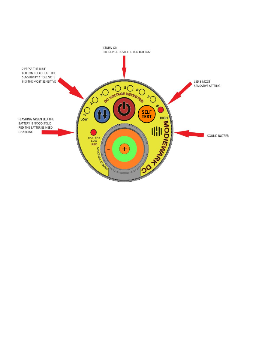
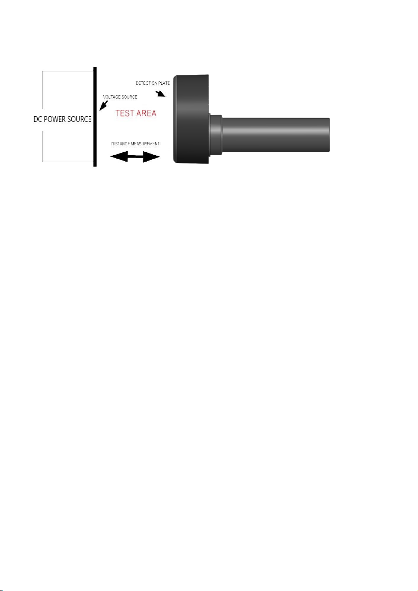
The DC50 tester is designed to pick up an electric field emanating from an
active DC source as low as 50v dc.
Static electricity can be found on almost any surface.
Static electricity is an imbalance of electric charges within or on the surface of a
material.
The charge remains until the indicator is moved away from the area or by means of
an electric current or electrical discharge.
A static electric charge can be created whenever two surfaces contact and
separate, and at least one of the surfaces has a high resistance to electric current
(and is therefore an electrical insulator).
The effects of static electricity are familiar to most people because it can be felt,
heard and visually seen as a spark as the excess charge is neutralized when
brought close to an electrical conductor, or a region with an excess charge of the
opposite polarity (positive or negative).
The familiar phenomenon of a static shock –more specifically, an electrostatic
discharge –is caused by the neutralization of charge.
Static electricity is everywhere and is all around us. static electricity can be generated by simply rubbing
a piece of plastic on your shirt and removing it.
Dealing with Static charge has been the hardest phase to overcome to
manufacture.

9
How to combat static electricity
Once a DC power source is terminated in a plastic insulted cable, but not
earthed (grounded), a static charge remains present on the insulation, this will
slowly dissipate over time.
The DC50 indicator will read this static residue left behind and over time the
indicator sensitivity lights will stop indicating.
From trials conducted it can take up to several minutes for the static charge to
dissipate. The time is dependent on the thickness of the insulating material
and its composition.
Earthing the cable instantly removes the static charge in the cable.
Alternatively, you can Spray the target area with antistatic spray.
Approach the area to be tested, if the device alarms, repeat the process until
the DC50 does not pick up any signal.
If you test where live DC supply is present and the power is turned off, the
indicator will still show a decreasing DC field (static discharge).
If the insulated cable is sprayed with the antistatic spray it will negate the static
charge showing the operator that no potential is present.

10
Usages
The indicator can be used where DC voltages are present.
•Electric trains 1500 vdc
•Electric trams 600vdc
•Underground mining vehicles 1800 vdc+
•Power station’s 50-600 vdc
•Control and switch gear 200 vdc
•Under sea direct current power lines 1000vdc+
•Solar arrays 200 to 1000vdc
•Electronic Environment’s where static is an issue.
•Aluminum Smelters
•Aircraft
--------
GL Mcgavin Pty. Ltd. cannot authorise the method of use. Power
distribution authorities have trained personnel who can advise on the
operation and use. This document is developed from general principles
and it may not be suitable for all conditions and localities contemplated
by it. This document may be used only on the condition that GL McGavin
Pty Ltd disclaims all liability.

11
DC Specifications
Size
225mm Long
Charge Time
2 x batteries 7 Hours
Voltage sensing
range
50 to VDC
Light source
8 high intensity Leds
Sound source
90 db piezo buzzer
Operating
temperature
-20 to 65 C deg
Water
Resistance
IEC IP6X (Safe when exposed to heavy rain).
Weight
750 g
Power System
Rechargeable Lithium-ion battery 1-day life in
rigorous activity.
Battery Life
7 hours
Cap Material
ESD POM (Acetyl) Black
Warranty
1-Year
Handle Material
Glass filled polypropylene
Included in the
Shipment
DC Voltage Detector,6 Batteries, Car Charger,
Charging Lead, Charger, Manuel, Msds, Air Pump,
Storage Case

12
DC Voltage Detector
Safety Information
The Fire and Rescue DC50 Tester was designed as a DC Proximity device to
eliminate the dangers of touch testing and earthing. It should be used by
trained and qualified personnel only.
When testing DC circuits always use caution and strictly adhere to proper
safety practices.
Above 500VDC proper high voltage procedures for testing should apply.
Wearing personal protective equipment is a necessary safety precaution.
Read the User Manual carefully before using the Indicator.
The DC50 is a Proximity device but if it should ever make contact with a live DC
conductor no harm to the indicator will occur but the Indicator cap will need to
be touched to dissipate the Static charge.
Prior to using the DC50 in the field, make sure to test and verify that sensitivity
settings are suitable for testing in that location.
Always check that the DC50 is working before using it in on site.
The risk of electrocution is paramount in and around high voltage.

13
Overview
The Fire and Rescue DC50 is a non-contact DC voltage tester that alerts users
when they approach an electrified source. Its advanced notification system is
designed to warn the user of the presence of voltage and current within a
proximate area. DC internal sensors were designed to detect both electrical
(V/m) and magnetic (T) fields. Radiated electric and magnetic fields increase
with higher distribution voltages and decrease with distance and/or shielding.
Once an energized source is detected, the user is notified first by LED lighting
of the approximate distance and then is followed by indicating piezo buzzer.
These warnings are shown to the user by the line of LED lights.
Typical Uses
•Identify live conductors.
•Detect residual or induced voltages.
•Identify energized lines after power outages.
•Find energized lines underground.
•Detect energized threats after natural disasters.
A product of
www.glmcgavin.com.au
All rights reserved © 2021

14
WARNINGS
DC50 only detects DC Voltage.
Every energized DC conductor is surrounded by an electric field.
As you move closer to the conductor, the electric field will become stronger.
Lower voltages have a weaker field strength and will have a shorter warning distance.
Electric fields that have a stronger field strength, will have a greater warning distance.
Underground PRIMARY cables are both insulated and shielded. The shield is a
conductor, it is grounded, and will nullify the electric field.
Moulded cable terminators such as elbows - like the cables they are installed on - are
both insulated and shielded and will nullify the electric field.
Live conductors lying on the ground should be tested where they leave the earth
situation for test confirmation.
Electric fields will couple to the ground thus drastically reducing warning distances.
Treat all conductors as “live” unless or until there is a visible break from a live source
and a ground is in place.
Always use proper high voltage procedures, including personal protective equipment,
when working near or around high voltage equipment or conductors.
Before using the Fire and Rescue DC50 in hand, learn the proper holding method. Not
using the proper positioning will prevent voltage from being detected.
Warning distances will be greatly reduced in high humidity and rainy environments.
Never submerge in water. If fully submerged, moisture could enter the enclosure and
damage detection sensors leading to reduced warning distances or failure to detect a
“live” voltage.

15
Limited Warranty and Limitation of
Liability
1. Effective November 1, 2017, this warranty applies to all products
manufactured and sold by G.L McGavin PTY.LTD. (the “Products”).
2. NOTICE: READ THIS LIMITATION OF WARRANTY AND LIABILITY BEFORE
BUYING OR USING THE PRODUCTS CONTAINED HEREIN.
3. It is impossible to eliminate all risks associated with the use of the
Products. Risks of serious injury or death, including risks associated with
electrocution, arcing and thermal burns, are inherent in work in and
around energized electrical systems. Such risks arise from the wide variety
of electrical systems and equipment to which Products may be applied,
the manner of use or application, weather and environmental conditions
and/or other unknown factors, all of which are beyond the control of
G.L.McGavin’s Equipment. G.L. McGavin Pty Ltd does not agree to be an
insurer of these or other risks and shall have no liability for any claims
arising from these or other risks inherent in electrical systems.
4. WHEN YOU BUY OR USE THESE PRODUCTS, YOU AGREE TO ACCEPT
THESE RISKS.
5. G.L.McGavin warrants to the original purchaser that the Products will be
free from defects in material and workmanship under normal, with regular
service and preventative maintenance, for a period of one (1) year from
the date of shipment (the “Warranty Period”). Should any failure to
conform with this warranty be found during the Warranty Period, you
must notify G.L.McGavin of your claim within thirty (30) days of discovery,
and within the Warranty Period. Your failure to give notice of claims of
breach of warranty within the Warranty Period shall be deemed an
absolute and unconditional waiver of claims for such defects. G.L.McGavin
will have no responsibility to honour claims received after the date the
applicable Warranty Period expires.

16

17
6. Upon notice of your claim, G.L.McGavin will provide a return authorization
number and further instructions on how to return the product for service.
You must follow G.L.McGavin’s instruction. You are responsible for all
Product removal, handling, re-installation, and shipping (both to and from
G.L McGavin.). Products returned for repair, as well as repaired or
replacement Products, shall be sent postage / freight prepaid. After
receipt of a product that G.L McGavin determines is defective, G.L
McGavin will, at its option, either (1) repair (or authorize the repair of) the
Product or (2) replace the Product, subject to the following: The Products
are made using parts sourced from a variety of manufacturers. Due to the
rapidly changing technology environment, parts may become obsolete /
unavailable over time (end of life). In the event that a Product cannot be
repaired or replaced due to unavailability of parts, G.L McGavin will use
commercially reasonable efforts to obtain substitute parts or conduct
work around design, but cannot guarantee its ability to do so.
7. Items not found defective will be returned at your expense, or failing
receipt of instruction from you on return of such items within five (5)
business days of our notice to you that the product is not defective, G.L
McGavin may dispose of the product at its discretion and with no liability
to you. G.L McGavin Equipment, determination of defects is final. Products
repaired or replaced during the Warranty Period shall be covered by the
foregoing warranties for the remainder of the original Warranty Period or
ninety (90) days from the date of delivery of the repaired or replaced
Products, whichever is longer.
8. LIMITATIONS
•This warranty is void in the event of misuse, alteration, faulty
installation, or misapplication of the product.
•This warranty does not cover failure of product or components due to
any ACT OF NATURE, including, but not limited to, lightning, floods,
hurricanes, tornadoes or any other such catastrophic events.
•G.L McGavin does not warrant any third-party products or associated
hardware or their performance or suitability for use and application.

18
•All repairs must be authorized by G.L McGavin. Unauthorized repairs
will not be reimbursed under any circumstances.
•G.L McGavin is not required to make replacement or loaner equipment
available while Products are being repaired or replaced, or to
compensate you for any in/out labour charges or expenses associated
with removal, handling or re-installation of the products.
9. To the maximum extent permitted by law, this warranty and the remedies
set forth above are exclusive and in lieu of all other warranties, remedies
and conditions, whether oral or written, express or implied.
G.L MCGAVIN EXPRESSLY DISCLAIMS ALL OTHER WARRANTIES OF ANY
KIND, EXPRESS OR IMPLIED, INCLUDING WITHOUT LIMITATION IMPLIED
WARRANTIES OF FITNESS FOR A PARTICULAR PURPOSE,
MERCHANTABILITY AND NON-INFRINGEMENT.
IN NO EVENT SHALL GL MCGAVIN EQUIPMENT BE LIABLE FOR ANY
INDIRECT, INCIDENTAL, CONSEQUENTIAL OR SPECIAL DAMAGES
RESULTING FROM THE USE OR HANDLING OF THESE PRODUCTS. THIS
SHALL INCLUDE, BUT IS NOT LIMITED TO, LOST PROFITS OR REVENUE,
LOSS OF USE OF THE PRODUCTS, COST OF SUBSTITUTE PRODUCTS,
FACILITIES OR SERVICES, OR DOWNTIME.
10. IN NO EVENT SHALL GL MCGAVIN. HAVE ANY LIABILITY FOR ANY THIRD-
PARTY PRODUCTS OR ASSOCIATED HARDWARE, OR CUSTOMER-OWNED
SYSTEMS, EQUIPMENT OR SOFTWARE.
11. G.L.McGavin must have prompt notice of any claim so that an immediate
product inspection and investigation can be made. Buyer and all users
shall promptly notify G.L.McGavin of any claims, whether based on
contract, negligence, strict liability, or other tort or otherwise be barred
from any remedy.

19
Problem
Solution
All LED lights and
buzzer are activated
when the device is
first turned on
Ground the cap and rotar.Turn the device off and back on,
decrease the sensitivity level down, the indicator is picking up
an eclectic field, remember the field can also be a static
charge. On LED setting 8 the indicator is extremely sensitive.
Device does not
power up when red
button is depressed.
Try unscrewing the handle anti-clockwise then turn the handle
clockwise to tighten to overcome a bad battery connection.
Check polarity of battery’s are the correct way.
Device does not
power up when red
button is depressed
Check the battery light is not RED, Replace the batteries
ensure the batteries are charged
The blue sensitivity
button does not work
Turn the unit off and back on. Return to manufacturer.
Rotor does not spin
Try the above solutions, also Check for obstructions, ensure
the rotor has not been bent and is stuck, try and straighten the
rotor. Get the rotor to spin freely, or return to manufacturer.
Device has been wet
The electronics in the device have been sealed, Remove the
handle (power source). Shake out the device, try and get all of
the water out, blow out excess water with air pump, leave in
the sun to air dry.
Device is not
sensitive enough,
and is not picking up
power
Restart device, ensure the power source is over 50VDC.The
indicator may not indicate if the field is too low to register.
Press the green self-button to ensure the unit is functioning
correctly. Ensure the indicator is on the high setting (8)
Device does not
indicate the cable
could be armored
The electric field in the cable has been nullified by the cable
shield, the indicator will not work.
The device is picking
up a signal too far
away to distinguish
between conductors
Drop the sensitivity one level at a time, level LED 1 is the least
sensitive setting. Only on DC8 Models.
Detector actives
when your leg is
lifted from the
ground, or when
walking
By lifting your leg, earth connection has been halved, turn the
indicator off and back on and operate with only one-foot
touching earth, by restarting the indicator it will automatically
readjust to the conditions. recommendations are to use the
indicator in stationary position.

20
It is the manufacturers recommendation that only trained personnel use this
equipment.
Ensure the operation manual has been read and understood.
The indicator is designed to be used as a visual and audible alarm device for
the protection of the operator.
Contact GL McGavin
Ph: 02 4952 6304
Phone Int: +61 2 4952 6304
F: 02 4956 1054
Int Fax: +61 2 4956 1054
43-45 Orlando Road, Lambton NSW 2299 Australia
PO Box 83, Lambton NSW 2299 Australia
Table of contents