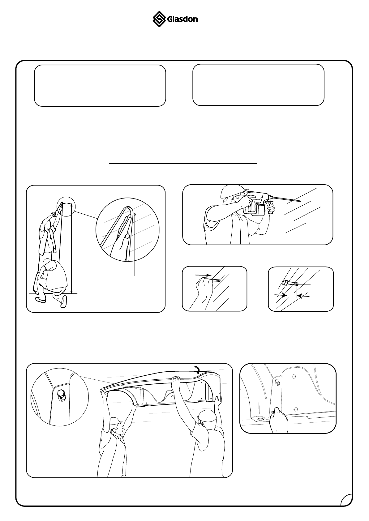
1. Firstly establish the location your Eclipse canopy
is to be sited. To install your canopy we
recommend installing from the upper left fixing
key hole. From the ground measure approximately
2330mm upwards on the wall and mark the centre
using a pencil/scriber (diagram A).
2. Using a 12mm masonry drill bit and a hammer drill,
drill the marked hole to a depth of 110mm (diagram B).
3. Remove the washer from one of the anchors and
hammer the anchor into the drilled hole making sure it
is fully inserted (diagram C). Tighten the anchor using a
17mm socket until it is firmly secure. Once secure, then
unscrew the bolt until it is around 30mm proud of the
wall (diagram D) for the canopy to be hooked onto.
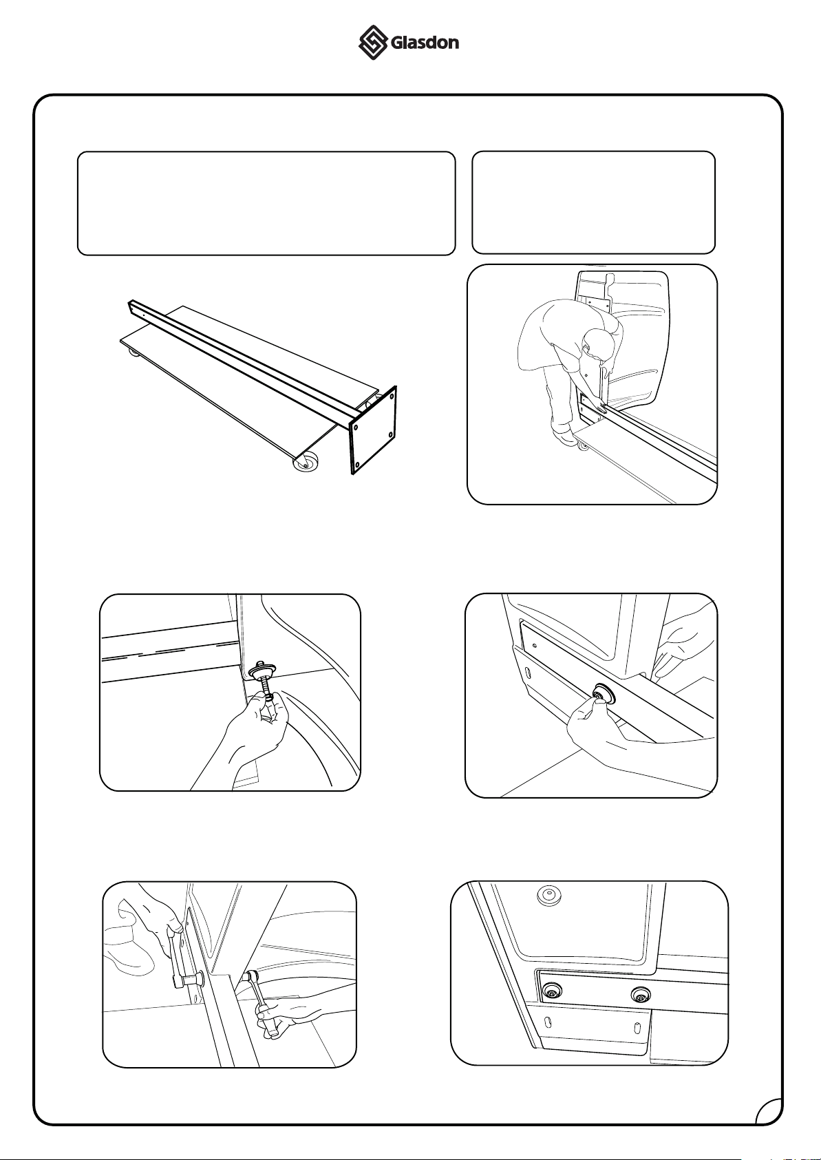
KIT CONTENTS
1 x 1.4m Canopy 4 x Cover rings
4 x Wall fixings 1 x Foam Strip
4 x 50mm Washers
4 x Cover caps
TOOLS REQUIRED
Tape measure 17mm Socket bit
Hammer battery drill Hammer
12mm Masonry drill bit Spirit Level
Socket set
ECLIPSE CANOPY INSTALLATION INSTRUCTIONS
INSTALLATION INSTRUCTIONS
NOTE:
A. B.
C. D.
IMPORTANT NOTE: ENSURE ALL RELEVANT PERSONNEL READ THE POINTS LISTED WITHIN THIS LEAFLET AND
THAT A COPY IS GIVEN TO STAFF INVOLVED WITH THE INSTALLATION AND MAINTENANCE OF THIS PRODUCT.
Anchor
Anchor
Hole marking for
top left key hole
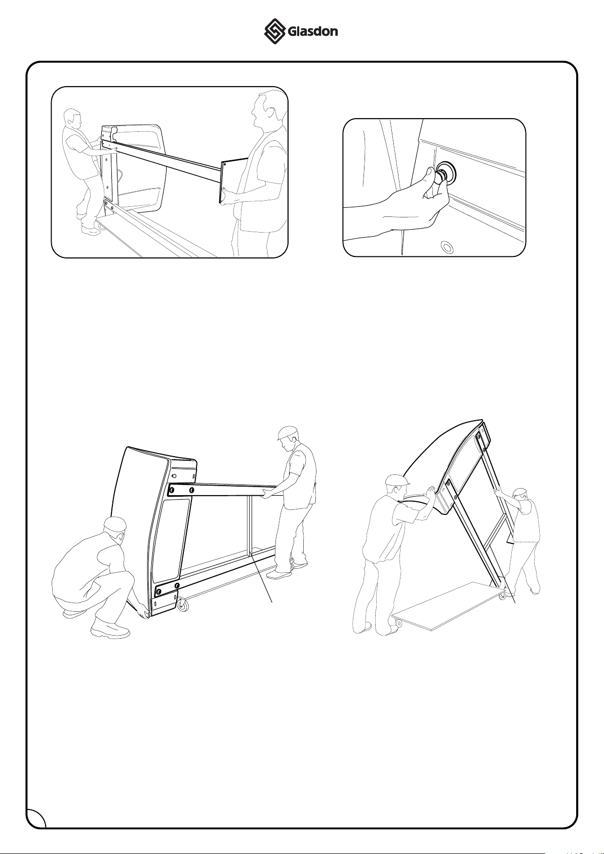
NOTE: A minimum of 2 persons are required for this installation.
Weight of the canopy: 21kg
2330
30
4. Lift the canopy up and position the top left key hole slot on the protruding
bolt. Pivot the canopy up at the opposite side ensuring the canopy is level
with the mortar lines or by using a spirit level. (diagram E).
5. Mark the remaining 3 hole
centres of your canopy using a
pencil or scriber (diagram F). The
hole positions are indicated by the
arrows above and below the fixing
slots located in the recesses in the
rear of the canopy. Carefully
remove the canopy from the bolt
and place it down on the floor.
Bolt
1
E. F.
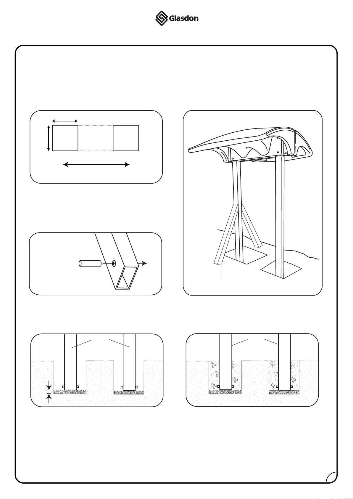
The canopy is supplied with wall fixings suitable for solid walls of adequate strength. Although most solid
and cavity walls can typically support the canopies, they should be assessed for adequate strength and
stability by a suitably qualified person. There are a number of other anchors and resin fixings that are
probably suitable for your particular site conditions, and the appropriate fixing type should be chosen.