INSTALLATION & OPERATION
INSTR CTIONS
BEFORE INSTALLING THE CABLEMASTER CRM-30™:
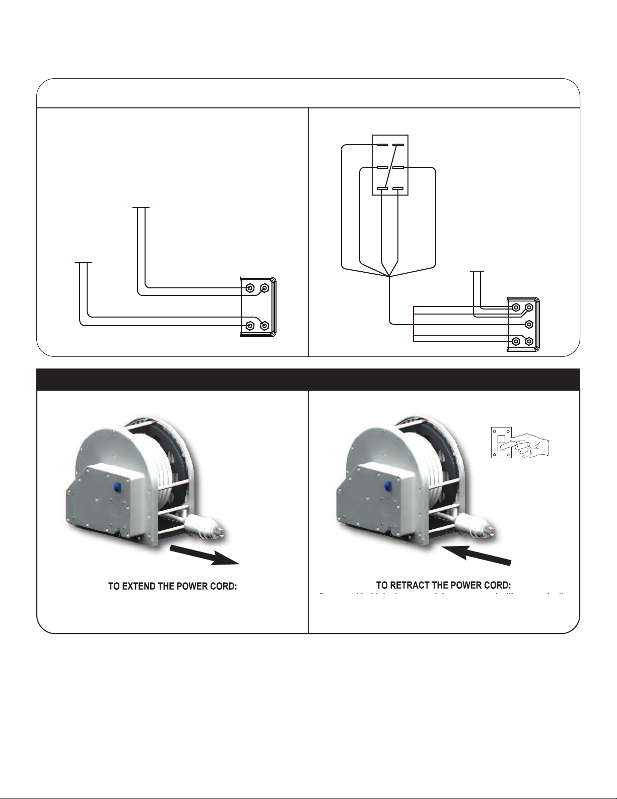
Before installing the mounting bracket, identify the compartment where the Cablemaster™ will be installed. The Cablemaster™ MUST BE installed in
an area that is sheltered from the elements. For proper operation of the Cablemaster™ the power cord exit MUST be centered with the center of the
reel or the power cord will wrap on one side of the reel closest to the exit and could bind during retraction. If the exit is N T centered, you will need to
purchase additional accessories to aid in this installation. Measure the compartment to insure there is enough space for the Cablemaster™. Make sure
that a 3-1/2” space (minimum) is allowed for electrical connections on the circuit breaker side of the Cablemaster™.
STEP 1. MOUNT CABLEMASTER™ (Fig. 1)
The Cablemaster™ comes with a mounting bracket for easy installation of the
unit. Install the mounting bracket using bolts or screws (installer supplied) fas-
tening the bracket to the floor, wall or top of the compartment.
nce the mounting bracket is secured to the compartment space you may con-
nect the Cablemaster™ to the mounting bracket. Align the lock notches on the
base of the unit with the corresponding pegs on the mounting bracket. nce the
notches have been properly aligned, slide the unit locking it into place with the
mounting bracket. Attach the Cablemaster™ to the mounting bracket using the
bolts, washers and nuts supplied.
STEP 2. INSTALL HA SE PIPE [optional] (Fig. 2)
The installation of the Hawse Pipe is optional. You may also use your existing
Hawse Pipe or any storage space door that is accessible to where you want the
power cord to exit.
If you purchased a Hawse Pipe from Glendinning, follow these instructions —
Using the template provided with the Hawse Pipe, mark the location of the Hawse
Pipe. Before drilling or cutting, check to be certain that the area behind the Hawse
Pipe is free of wires, plumbing or structural supports. Mounting surface should be
a minimum 1/2” thick. Proper thickness may be achieved by using a butt block of
marine-grade plywood behind the mounting surface.
Cut the Hawse Pipe’s center hole and drill the four (4) 1/4” mounting holes. Using
740 Century Circle • Conway, SC 29526 • P: 843-399-6146 • F: 843-399-5005
www.glendinningprods.com SML-CRM30-INSTAL
LIMITED WARRANTY
PROD CT(S) COVERED BY THIS LIMITED WARRANTY: CABLEMASTER™ - MODEL CRM-30
1. GLENDINNING MARINE PRODUCTS, INC. warrants to the original consumer purchaser that the Cablemaster™ - Model CRM30 will be free from defects in material and workmanship under normal use and service for a period of
one (1) year from the date of purchase.
2. This LIMITED WARRANTY applies t defects in material and workmanship. It does not apply to chromeplated or anodized finish or to power cable damage caused by inadequate cable storage area or installation not in accordance
with GLENDINNING MARINE PROD CTS, INC. specifications.
3. This LIMITED WARRANTY is v id if the product has been damaged by accident or unreasonable use, neglect, improper installation, or other causes not arising out of defects in material or workmanship.
4. T btain perf rmance f this LIMITED WARRANTY obligation the original purchaser should contact GLENDINNING MARINE PROD CTS, INC. for instructions concerning removal and shipping of the defective component. pon
compliance of the foregoing procedure all warranted defects will be repaired, or at GLENDINNING MARINE PROD CTS, INC. option, the complete unit replaced and returned to the consumer, shipping charges prepaid.
5. GLENDINNING MARINE PRODUCTS, INC. does not assume the costs of removal and/or installation of the product or any other incidental costs which may arise as a result of any defect in materials or workmanship.
THIS WARRANTY IS IN LIE OF ALL OTHER EXPRESS WARRANTIES. ANY WARRANTY IMPLIED BY LAW INCL DING WARRANTIES OF MERCHANTABILITY OR FITNESS, IS IN EFFECT ONLY FOR THE D RATION OF
THE EXPRESS WARRANTIES SET FORTH IN THE FIRST PARAGRAPH ABOVE. NO REPRESENTATIVE OR PERSON IS A THORIZED TO GIVE ANY OTHER WARRANTY OR TO ASS ME FOR GLENDINNING MARINE
PROD CTS, INC. ANY OTHER LIABILITY IN CONNECTION WITH THE SALE OF IT’S PROD CTS. GLENDINNING MARINE PROD CTS, INC. WILL NOT BE LIABLE FOR ANY CONSEQ ENTIAL DAMAGES RES LTING FROM
THE SE OR INSTALLATION OF IT’S PROD CTS.
P/N INSTALLATION ACCESSORIES
04043 Horizontal Pipe Extension Kit
Allows the Cablemaster™ to be mounted an extended distance from the Hawse
Pipe Assembly.
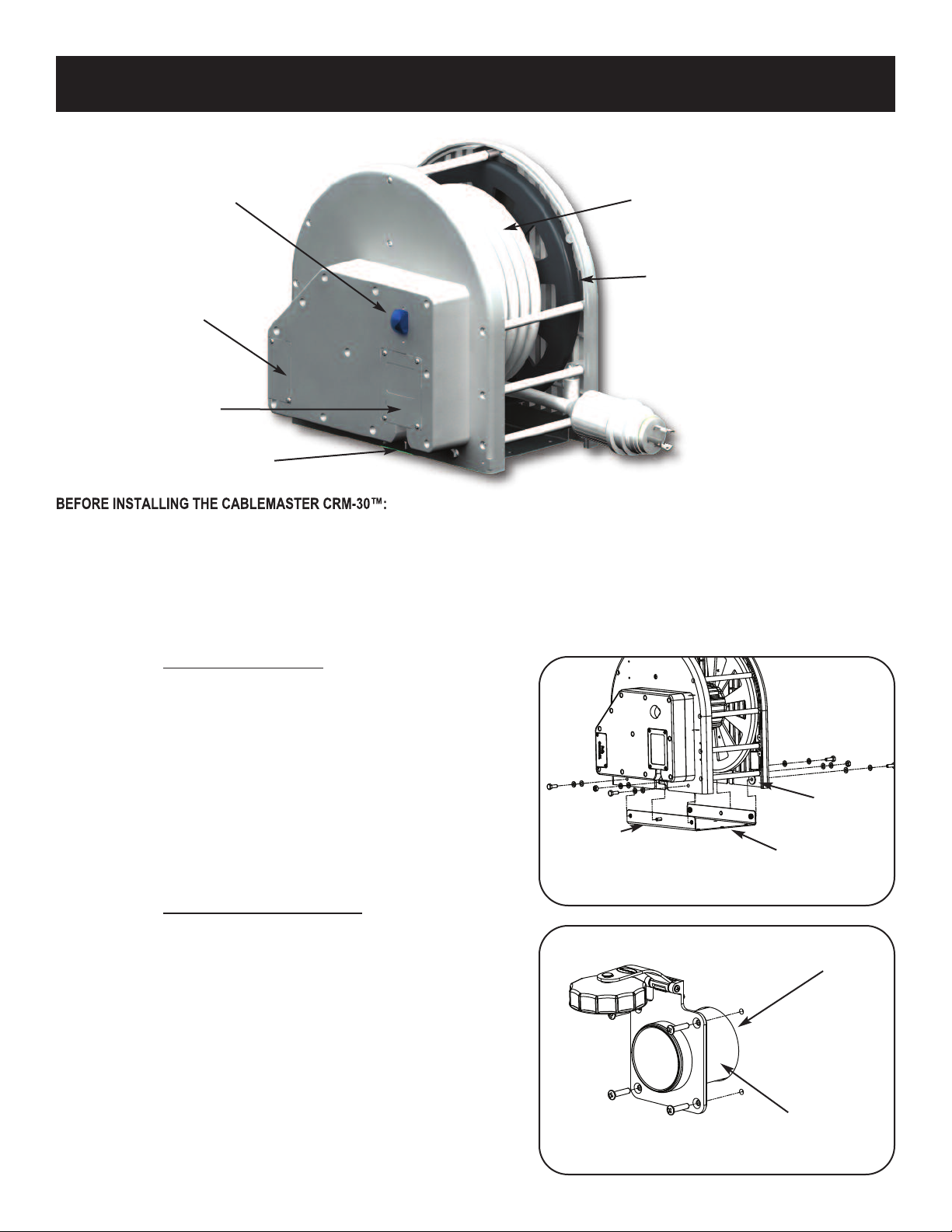
CABLEMASTER CRM-30
Circuit Breaker
(optional)
“Pigtail” (optionall)
DIMENSI NS:
11.09” [282mm] W
14.08” [358mm] H
13.75” [350mm] D
Reel
DC Control Panel
AC Control Panel
105ºC rated cordset
Fig. 1
Install mounting bracket & mount unit
Use bolts or screws to
mount bracket to surface
Attach unit to
mounting bracket
Align peg with notches
Fig. 2
Install Hawse Pipe (optional)
Make sure gasket is installed
between hawse pipe flange
and exterior surface
Use template to cut / drill hole
in surface