Nexans EUROMOLD K800PB/G User manual

This product should be installed only by competent personnel trained in good safety practices involving
high voltage electrical equipment. These instructions are not intended as a substitute for adequate
training or experience in such safety practices. These instructions do not attempt to provide for every
possible contingency. Failure to follow these instructions could result in damage to the product and
serious or fatal injury. IMPORTANT : Cable and associated apparatus must be de-energised, locked out,
and tagged prior to product installation.
For installation on a 480TB, 484TB or 489TB tee connector or a 800PB, 804PB
or 809PB coupling connector tightened with a clamping screw (type 1)
OR
clamping
screw
clamping
screw
OR tightened with a stud and flange nut (type 2)
OR
CAUTION : Read instructions thoroughly and completely prior to beginning installation.
Installation instructions for separable coupling connector
K800PB/G
Up to 24 kV
Only to be used on copper wire screened cable with extruded semi-conductive screen
and conductors of copper or aluminium.
For installation on a 480TB, 484TB or 489TB tee connector or a
800PB, 804PB or 809PB coupling connector.
M16
flange nut
M16
flange nut
WARNING :
CHANGED INSTALLATION
Page 1 of 14
IS97180-ENG - K800PB/G-CW45-CA0
18 November 2019 - Revision 2 - Supersedes edition of 28 September 2018
IS97180-ENG - K800PB/G-CW45-CA0 - Revision 2
For information only

1 x Installation rod
(for conductor sizes
185 up to 300 mm²)
Required components for the connector installation :
Installation
instructions
Water sealing
mastic, type MWS
(optional)
Roll adhesive
tape Silicone grease
+ wipers
+
Gloves
3 x Coupling
connector housing
800BP
3 x Contact rod
and stud
Nylon vent rod
3 x Cable reducer
CA0-W
Check if the diameter over cable core insulation is in accordance with
the cable reducer range as indicated in table below:
Cable reducer size
(see label on cable reducer)
CA0-11
CA0-15
CA0-18
CA0-21
CA0-27
12.0
16.0
19.0
22.0
28.5
19.0
26.5
32.6
34.6
37.5
Dia. over core insulation (mm)
min max
3 x Conductor
contact - TBC-X
or TMBC-X
or
IS97180-ENG - K800PB/G-CW45-CA0 - Revision 2
Page 2 of 14
For information only
NB : Only one phase is shown in these instructions. Make off all three phases
the same way. Use a cable conversion kit for 3-core cables.
EQUIPMENT
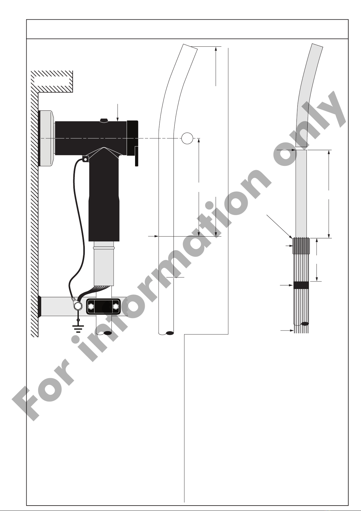
245
necessary length of screen wire earth connection
cut back
point of
outer
sheath
outer cable
sheath
1Train the cable into the approximate finished
position next to the equipment bushing. Be sure
to allow enough extra length of screen wires
to connect to earth.
2Mark centre line « M » of the bushing.
3Remove the outer cable sheath to a point 245 mm
from the centre line « M » of the bushing.
Separable tee connector
or
first male connector
M
65
200
CUT
HERE
tape
marker
edge of the
outer sheath
copper
wires
4For indoor applications, bend the screen wires back
over the outer sheath and proceed to step no. 5.
For outdoor applications:
- Wrap one layer of water sealing mastic (type MWS)
around the outer sheath, flush with the end (25 mm
minimum width). Completely encircle the cable.
- Bend the screen wires back over the mastic and
along the outer sheath, pressing them into the
mastic.
- Important: screen wires should not touch each
other when pressed into the mastic to prevent water
ingress.
5Apply a tape marker around the outer sheath 65 mm
from the edge.
6Cut the cable to a point 200 mm from the outer
sheath.
For outdoor
applications :
one layer of water sealing
mastic (type MWS)
Page 3 of 14
IS97180-ENG - K800PB/G-CW45-CA0 - Revision 2
For information only
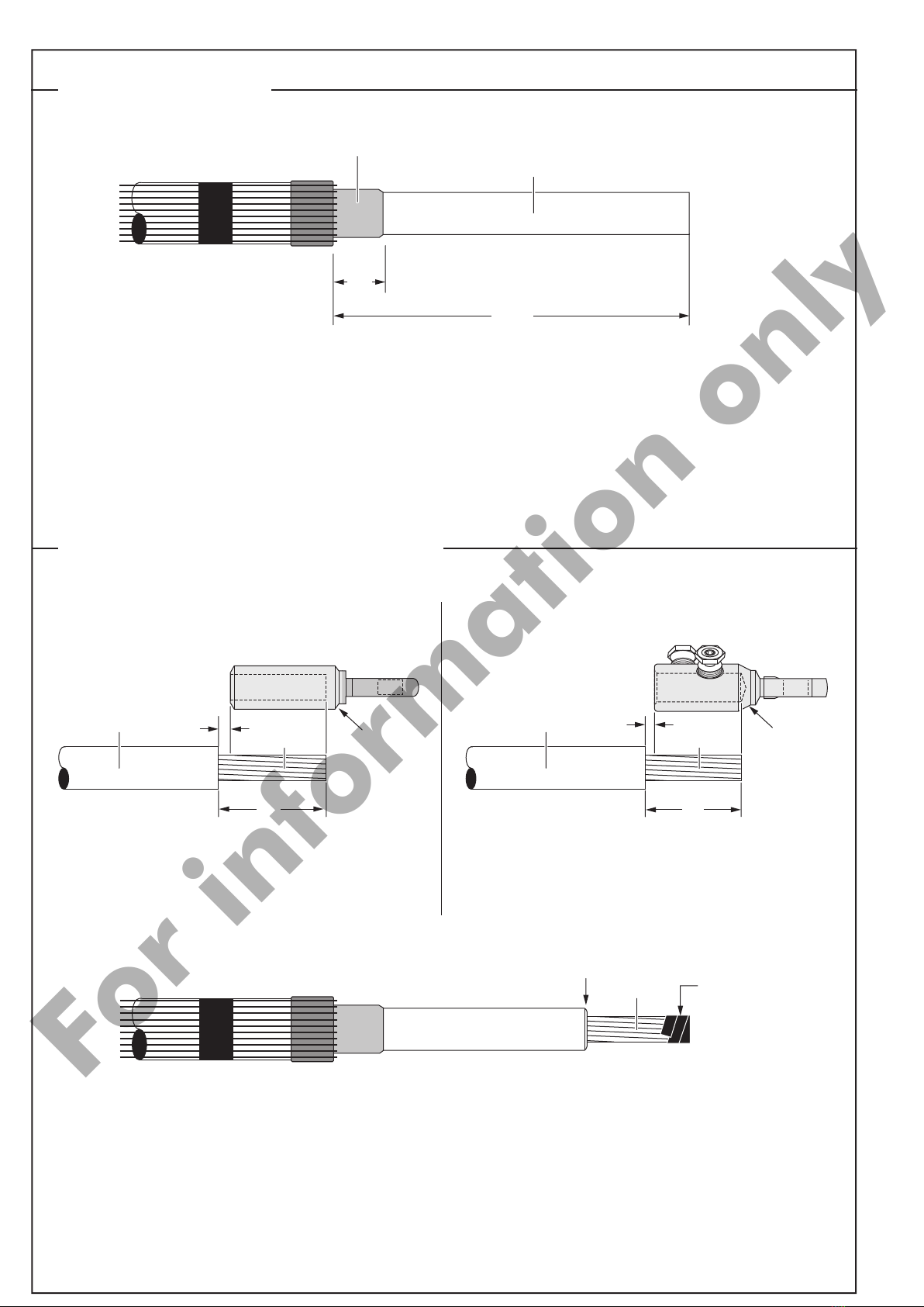
CABLE PREPARATION
30
semi-conductive screen
1Check distance of 200 mm.
2Remove the semi-conductive screen to a point 30 mm from the outer sheath.
For extruded easy strip semi-conductive screen:
Cut squarely taking care not to cut the core insulation.
For bonded extruded semi-conductive screen:
Use an appropriate pencilling tool. Make a clean transition between core insulation and semi-conductive screen.
200
core insulation
conductor protective
adhesive tape
2Slightly bevel the edge of the core insulation (max 2 mm).
3Thoroughly clean core insulation. Always wipe towards the screen wires.
4As a protection, wrap a few turns of adhesive tape around the conductor end.
bevel
REMOVAL OF THE CORE INSULATION
core insulation conductor
contact
conductor
1 A. Remove the core insulation from the conductor
for a distance « C » mm
(C= depth of contact bore + 10 mm).
1 B. Remove the core insulation from the conductor
for a distance « C » mm
(C= depth of contact bore + 10 mm).
A. Compression type contacts (Type TBC-X) B. Mechanical type contacts (Type TMBC-X)
10
C
core insulation conductor
contact
conductor
10
C
IS97180-ENG - K800PB/G-CW45-CA0 - Revision 2
Page 4 of 14
For information only

* USE ONLY THE SILICONE LUBRICANT SUPPLIED
1Lubricate* the indicated area: core insulation, semi-conductive screen, water sealing mastic and inner surface of the
reducer.
2Slide the reducer down the cable until flush with the tape marker.
3Remove the protective adhesive tape from the conductor.
INSTALLATION OF THE CABLE REDUCER
For conductor sizes 16 up to 150 mm²
core insulation
cable reducer
cable reducer
remove
protective
adhesive tape
lubricate
tape marker
1Slide the installation rod on to the conductor until it butts against the core insulation.
2Thoroughly clean installation rod and core insulation. Always wipe towards the screen wires.
3Lubricate* the indicated area: installation rod, core insulation, semi-conductive screen, water sealing mastic and
inner surface of the reducer.
4Slide the reducer on to the installation rod.
5Slide the reducer down the cable until flush with the tape marker. Take care to slide the reducer without hesitation
and in one smooth move.
6Remove installation rod and protective adhesive tape from the conductor.
core
insulation installation
rod
installation
rod
core insulation
lubricate
cable reducer
lubricate
tape marker
For conductor sizes 185 mm² up to 300 mm²
cable reducer remove
protective
adhesive tape
Page 5 of 14
IS97180-ENG - K800PB/G-CW45-CA0 - Revision 2
For information only
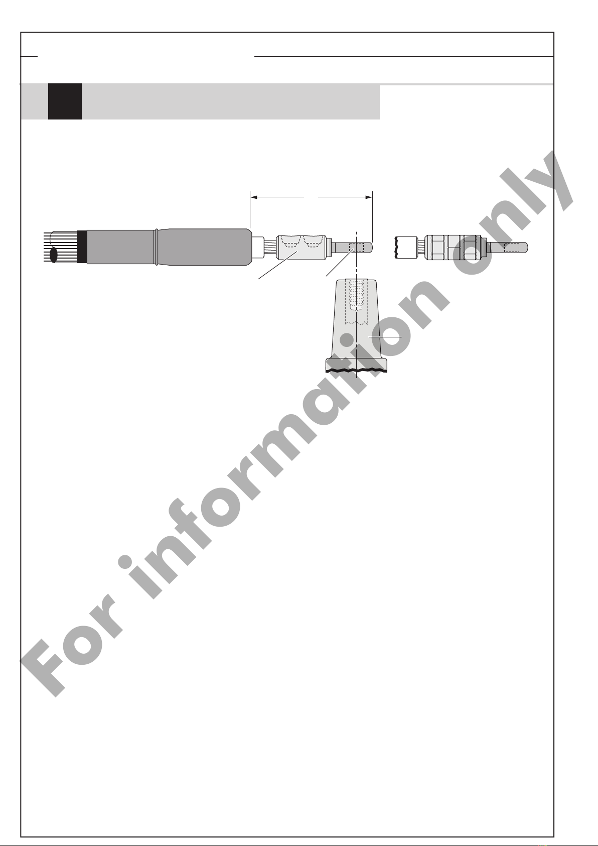
TIGHTENING OF THE CONTACT
equipment
bushing
1For aluminium conductors : before installing the conductor contact, wire brush the conductor.
2Fit the contact on to the conductor.
3Position the crimp contact taking care that the contact hole aligns with the bushing hole.
4Prior to crimping distance « Z » must be between 145 and 160 mm.
5Crimp the contact. Please refer to the crimp chart for crimp sequence.
6After crimping distance « Z » must be between 145 and 165 mm.
If necessary, adjust the position of the cable reducer until distance « Z » is within the tolerance range.
7Remove any burrs left after crimping and wipe-off excess inhibitor.
Compression type contacts (Type TBC-X)
A
Z
conductor
contact
deep indent
crimping DIN crimping
contact
palm
Please refer to the crimp chart supplied with the contact.
IS97180-ENG - K800PB/G-CW45-CA0 - Revision 2
Page 6 of 14
For information only

* USE ONLY THE SILICONE LUBRICANT SUPPLIED
COUPLING CONNECTOR INSTALLATION ON CABLE
coupling
connector
housing
lubricate
1Clean cable reducer, core insulation and contact.
2Lubricate* the inside of the connector housing and outer surface of the
cable reducer.
3Check if the outer cone interface is pointed towards the
bushing. Whilst preventing the cable reducer from
further movement down the cable gently slide the housing on the cable.
Its final position is reached when the centre
of the contact spade is along the axis of the interfaces of the connector.
4The cable reducer must stay in place during installation.
5Make sure the contact spade locks into the connector's housing.
6 Check that the ridge on the cable adapter is sitting at
5-25 mm below the connector housing.
holding tool
contact
palm
equipment
bushing
1For aluminium conductors : before installing the conductor contact, wire brush the conductor.
2Insert, if necessary, the centre ring into the contact barrel according to the table in the contact installation
instruction.
3Position the contact so that the contact hole aligns with the bushing hole.
4Tighten the contact. Please refer to the installation instruction included with the contact.
It is recommended to use a holding tool for ease of installation.
5After tightening, distance « Z » must be between 145 and 165 mm.
If necessary, adjust the position of the cable reducer until distance « Z » is within the tolerance range.
cable reducer
Before tightening
After tightening
conductor
contact
Z = 145 - 165
clean
5-25
ridge on
cable reducer
Mechanical type contacts (Type TMBC-X)
B
Page 7 of 14
IS97180-ENG - K800PB/G-CW45-CA0 - Revision 2
For information only

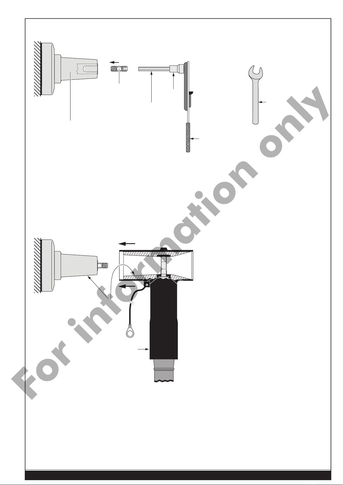
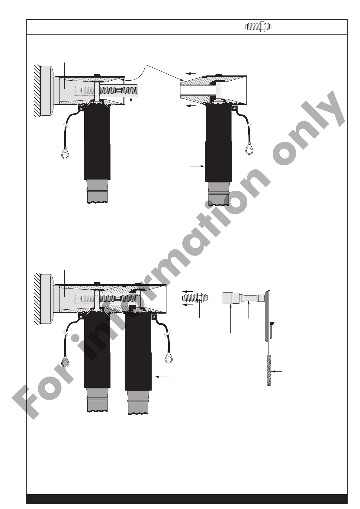
In case the tee connector has been already installed
(otherwise proceed to step no. 6).
cable
clamp
earthing
lead
copper wire
screen
clamping
screw basic
insulating
plug
Separable tee connector
protective
cap
1Remove the protective cap from the tee connector. Put the
protective cap aside in a clean and safe place for later re-use.
2Remove the basic insulating plug. Use a wrench with 22 mm
socket. Put the insulating plug aside in a clean and safe place
for later re-use.
3Type 1: remove the clamping screw. Use a wrench with a
22 mm socket and an extension. Put the clamping screw
aside in a clean and safe place for later re-use.
Type 2: remove the flange nut. Use a wrench with a 22 mm
socket and an extension. Put the flange nut aside in a clean
and safe place for later re-use.Check that M16 stud is still
mounted correctly.
Re-tighten to 30 Nm if required. Proceed with step 10
on page 10.
4Disconnect the earthing lead, copper wire screen and cable
clamps.
5Disconnect the tee connector from the bushing.
The bushing should be free.
basic
insulating
plug protective
cap
Type 1
Type 2
COUPLING CONNECTOR INSTALLATION ON TEE CONNECTOR
M16
flange nut
Page 8 of 14
IS97180-ENG - K800PB/G-CW45-CA0 - Revision 2
For information only
* USE ONLY THE SILICONE LUBRICANT SUPPLIED
8 mm
hex key
1/2" - 12,7 mm
torque wrench
8 mm
socket 13 mm
wrench
8mm
equipment
bushing
8Clean and lightly lubricate* both connector and bushing interface.
9Push the tee connector on to the bushing.
6Install M16 threaded stud into the bushing interface.
7Using a 13 mm wrench or a hex key of 8 mm, tighten the stud exerting 30 Nm (3 kgm or 22,1 foot-pounds).
connector
housing
lubricate
M16 stud
or
30 Nm
Page 9 of 14
IS97180-ENG - K800PB/G-CW45-CA0 - Revision 2
For information only

8 mm
hex key
1/2" - 12,7 mm
torque wrench
8 mm
socket
contact
rod
8mm
L≥70 mm
50 Nm
equipment
bushing
contact
rod
aInsert the contact rod on to the threaded stud.
zUse a torque wrench with a 8 mm socket and an hex key of 8 mm and tighten exerting 50 Nm (5 kgm or
36,9 foot-pounds) of torque.
In order to achieve the correct applied torque ensure that there is no lubricant on the threaded
parts.
For type 1 systems, using a clamping screw : proceed with step no 12 on page 11.
For type 2 systems, using a flange nut : proceed with step no 16 on page 12.
IS97180-ENG - K800PB/G-CW45-CA0 - Revision 2
Page 10 of 14
For information only
coupling
connector
eClean and lubricate* both female tee connector interface and male interface of the coupling connector.
rPush the coupling connector on to the contact rod of the tee connector. Take care not to damage the contact rod
during installation of the coupling connector.
22 mm
socket
1/2" - 12,7 mm
torque wrench
L ≥ 130 mm
extension
coupling
connector
22mm
* USE ONLY THE SILICONE LUBRICANT SUPPLIED
50 Nm
contact
rod
equipment
bushing lubricate
equipment
bushing
clamping
screw
tInsert the clamping screw into the threaded hole of the contact rod by hand.
yUse torque wrench with extension and a 22 mm socket and tighten exerting 50 Nm (5 kgm or 36,9 foot-pounds) of
torque.
In order to achieve the correct applied torque ensure that there is no lubricant on the threaded
parts.
Proceed with installing the basic insulation plug on page 13.
Type 1: clamping screw
Page 11 of 14
IS97180-ENG - K800PB/G-CW45-CA0 - Revision 2
For information only

coupling
connector
30 Nm
uInstall the M16 threaded stud into the contact rod.
iUsing a 13 mm wrench or a hex key of 8 mm, tighten the stud exerting 30 Nm (3 kgm or 22,1 foot-pounds).
In order to achieve the correct applied torque ensure that there is no lubricant on the threaded
parts.
oClean and lubricate* both female tee connector interface and male interface of the coupling connector.
pPush the coupling connector on to the contact rod of the tee connector. Take care not to damage the contact rod
during installation of the coupling connector.
qInstall the flange nut on to the threaded stud.
sUse torque wrench with extension and a 22 mm socket and tighten exerting 50 Nm (5 kgm or 36,9 foot-pounds)
of torque.
In order to achieve the correct applied torque ensure that there is no lubricant on the threaded
parts.
22 mm
socket
1/2" - 12,7 mm
torque wrench
L ≥ 130 mm
extension
coupling
connector
22mm
* USE ONLY THE SILICONE LUBRICANT SUPPLIED
50 Nm
contact
rod
M16
stud
equipment
bushing
equipment
bushing
Type 2: flange nut
M16
flange nut
IS97180-ENG - K800PB/G-CW45-CA0 - Revision 2
Page 12 of 14
For information only

* USE ONLY THE SILICONE LUBRICANT SUPPLIED
1Clean and lubricate* the insulating plug and the female interface of the coupling connector.
2Insert the plug into the connector and tighten assembly: use a torque wrench with a 6-point socket of 22 mm and
tighten exerting 30 Nm (3 kgm or 22,1 foot-pounds) of torque.
In order to achieve the correct applied torque ensure that there is no lubricant on the threaded
parts.
1/2" - 12,7 mm
torque wrench
22 mm
6-point socket
22mm
30 Nm
basic
insulating
plug
coupling
connector
equipment
bushing
lubricate
INSTALLATION OF THE CAP
INSTALLATION OF INSULATING PLUG
protective
cap
protective
cap
Installation on insulating plug BIPR without
voltage detection point:
- Clean the inside of the cap and the outside surface of
the connector and insulating plug.
- Place the nylon vent rod along the insulating plug
(see fig.) to exhaust the air during assembly of
the cap.
- Push the cap firmly over the connector and onto the
insulating plug.
- Press the cap on all sides to make sure it is well
positioned over the connector. Position the cap with
the pulling tab pointing downwards.
- Remove the nylon vent rod.
Installation on insulating plug BIPA with voltage
detection point:
- Clean the inside of the cap and the outside surface of
the connector and insulating plug.
- Place the nylon vent rod along the insulating plug
(see fig.) to exhaust the air during assembly of the cap.
- Push the cap firmly over the connector and onto the
insulating plug.
- Press the centre of the cap onto the locking
point until it snaps into place. Press the cap on all
sides to make sure it is well positioned over the
connector. Position the cap with the pulling tab
pointing downwards.
- Remove the nylon vent rod.
nylon vent
rod
nylon vent
rod
locking point
Page 13 of 14
IS97180-ENG - K800PB/G-CW45-CA0 - Revision 2
For information only
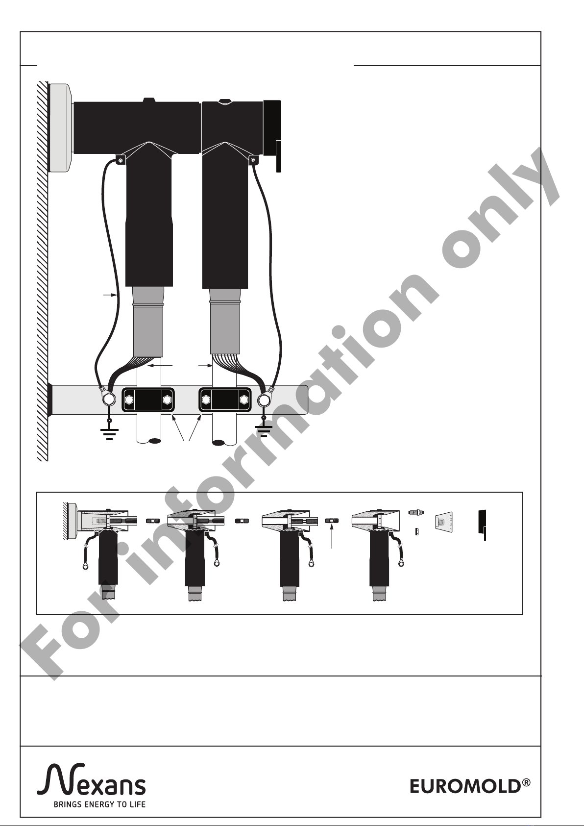
NOTE :
A connector/bushing mated combination should not be allowed to carry the full weight of the cable.
Therefore clamp the cable as close as possible to the connector.
IMPORTANT NOTES :
- Never disconnect connectors from energised equipment nor energise disconnected connectors without
previously installing on their appropriate corresponding mating part.
- Do not allow hydrocarbon oils or solvents to contaminate the E.P.D.M. rubber.
In the event of contamination, wipe the surface clean with a dry cloth.
system
earth
system
earth
cable
clamp
1Bend back the screen wires along the outer
sheath to form a pig tail.
2Connect the earthing lead and screen wires to
the system earth.
earthing
lead
CONNECTOR EARTHING AND CABLE CLAMPING
screen
wires
Nexans Network Solutions NV - div. EUROMOLD
Zuid III - Industrielaan 12
B-9320 EREMBODEGEM-AALST – BELGIUM
Tel: +32 (0)53/85 02 11 – Telefax: +32 (0)53/83 10 13
In case more than one coupling connector is to be installed, repeat all required steps.
or
only with
flange
nut
IS97180-ENG - K800PB/G-CW45-CA0 - Revision 2
Page 14 of 14
For information only
Table of contents
Other Nexans Cables And Connectors manuals

Nexans
Nexans N-HEAT MILLIMAT User manual

Nexans
Nexans Euromold K480TB/G User manual

Nexans
Nexans N42i.900 User manual

Nexans
Nexans ABS1335 User manual

Nexans
Nexans Euromold K489TB/G User manual

Nexans
Nexans Euromold K200LR User manual

Nexans
Nexans 400AR-8 User manual

Nexans
Nexans OutDrop 2+ User manual

Nexans
Nexans OUTDROP 2+ SFM Series User manual

Nexans
Nexans XPLORER Series User manual
Popular Cables And Connectors manuals by other brands


Echomaster
Echomaster P-BUA-PROMASTER CITY installation manual

Energenie
Energenie DSP-HDMI-21 user manual

PCB Piezotronics
PCB Piezotronics 010P20 Installation and operating manual

Roline
Roline 14013492 user manual

Rocket Fish
Rocket Fish RF-G1182 Quick setup guide

M-system
M-system 18KBXC-K5 instruction manual


