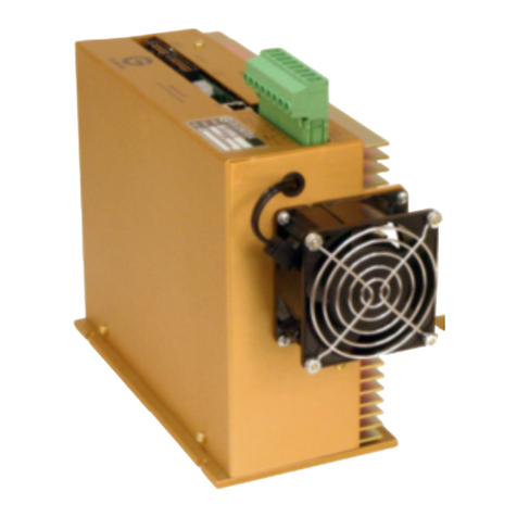
Glentek SMA8730 Installation and operating instructions

OPERATION
&
SERVICE MANUAL
Model SMA8730
Brushless Amplifier System

2GLENTEK Inc., 208 Standard Street, El Segundo, California 90245, U.S.A. (310) 322-3026
SMA8730
Table of Contents
Introduction...................................................................................... 5
Chapter One: Description, Features and Specifications
1.1 Description....................................................................................... 6
1.1.1 Standard Encoder to Sine Mode .................................................................6
1.1.2 Twang Mode................................................................................................6
1.2 Features........................................................................................... 6-8
1.2.1 Single Amplifier Module (SMA8730-1A-1)...................................................6-8
1.3 Specifications................................................................................... 9-10
1.3.1 Amplifier Module (SMA8730-1A-1)..............................................................9
1.3.1.1 Input and Output Power................................................................9
1.3.1.2 Signal Inputs.................................................................................9
1.3.1.3 Digital Inputs.................................................................................9
1.3.1.4 System..........................................................................................9
1.3.1.5 Outputs.........................................................................................9
1.3.2 Mechanical ..................................................................................................10
Chapter Two: Theory of Operation
2.1 Current Mode vs Velocity Mode....................................................... 11
2.2 Protection Circuit.............................................................................. 11
Chapter Three: Model Numbering
3.1 Introduction...................................................................................... 12
3.2 Amplifier Module.............................................................................. 13
Chapter Four: Installation Procedure
4.1 Introduction...................................................................................... 14
4.2 Mounting.......................................................................................... 14
4.3 Wiring............................................................................................... 14-16
4.3.1 RFI/EMI and Wiring Technique...................................................................14
4.3.2 Wire Size and Type.....................................................................................15
4.3.3 Connector Size and Type............................................................................15
4.3.3.1 The Power and Motor connector of the Amplifier Module............15
TABLE OF CONTENTS

3GLENTEK Inc., 208 Standard Street, El Segundo, California 90245, U.S.A. (310) 322-3026
SMA8730
4.3.3.2 The Signal Connector...................................................................16
4.4 Amplifier Module Connections(SMA8730-1A-1).............................. 17-18
4.4.1 Power and Motor Connections - TB1..........................................................17
4.4.2 Signal Connections for the Encoder to Sine Mode Amplifier - J1................17
4.4.3 Signal Connections for the Encoder to Sine Mode Pre-amp - J4 and J5....18
Chapter Five: Configuration
5.1 Introduction...................................................................................... 19
5.2 Logic Input Configuration................................................................. 19
5.3 Encoder to Sine Mode Amplifier Configuration................................ 19-23
5.3.1 +15V/+5V Logic Level Configuration ..........................................................20
5.3.2 Standard Configuration for Encoder to Sine Velocity Mode
and Current Mode........................................................................................20
5.3.3 Tach Lead ..................................................................................................20
5.3.4 Tach - Reverse Configuration ....................................................................20
5.3.5 Motor - Reverse Configuration ...................................................................20
5.3.6 Coarse Balance ..........................................................................................20
5.3.7 Hall 60/120 .................................................................................................21
5.3.8 Encoder - Reverse Configuration ...............................................................21
5.3.9 Rotary Motor (S3) Settings..........................................................................21
5.3.10 Linear Motor (S3) Settings...........................................................................21
5.3.11 Trap Only - Forced Hall ..............................................................................22
5.3.12 Range .........................................................................................................22
5.3.13 Encoder Configuration ................................................................................22-23
Chapter Six: Start Up and Calibration
6.1 Introduction...................................................................................... 24
6.2 Initial Start Up .................................................................................. 24
6.3 Phasing Procedures......................................................................... 24-26
6.4 Encoder to Sine Mode Amplifier Calibration.................................... 26-29
6.4.1 Encoder to Sine Mode Amplifier Calibration Procedure - Velocity Mode ....26-27
6.4.2 Encoder to Sine Mode Amplifier Calibration Procedure - Current Mode.....28
6.5 Calibration Setup Record................................................................. 29
TABLE OF CONTENTS
4GLENTEK Inc., 208 Standard Street, El Segundo, California 90245, U.S.A. (310) 322-3026
SMA8730
Chapter Seven: Maintenance, Repair and Warranty
7.1 Maintenance.................................................................................... 30
7.2 Amplifier Faults................................................................................ 30-32
7.2.1 Table of Fault LED Conditions ....................................................................30
7.2.2 Under Voltage Fault.....................................................................................31
7.2.3 Motor Over Temp Fault...............................................................................31
7.2.4 High Speed Electronic Circuit Breaker (HS/ECB) Fault..............................31
7.2.5 Low-Speed Electronic Circuit Breaker (LS/ECB) Fault ...............................31
7.2.6 Over Temp Fault .........................................................................................32
7.2.7 Over Voltage Fault.......................................................................................32
7.2.8 Hall Error Fault ............................................................................................32
7.2.9 Resetting A Fault.........................................................................................32
7.3 Amplifier Failure............................................................................... 33
7.4 Factory Repair ................................................................................. 33
7.5 Warranty.......................................................................................... 34
Appendix A: Amplifier Drawings
SMA8030 Brushless Power Board Installation Schematic
(8030-1037)..................................................................................... 36
SMA8030 Brushless Power Board Assembly Drawing
(8030-1032)..................................................................................... 37
SMA8730-1 Encoder to Sine Amplifier Module Installation
(8030-1036)..................................................................................... 38
Appendix B: Personality Module (Pre-Amp)
SMA8730 Encoder to Sine Mode Installation Schematic (8000-2432).... 40-41
SMA8730 Encoder to Sine Mode Assembly Drawing (8000-2430)......... 42-43
TABLE OF CONTENTS

5GLENTEK Inc., 208 Standard Street, El Segundo, California 90245, U.S.A. (310) 322-3026
SMA8730
Introduction
Glentek's brushless DC motors and amplifiers offer the ultimate in low maintenance and high
performance motion-control. Glentek offers a full line of matched motors and amplifiers to meet
virtually every motion-control application.
This manual provides all the technical information necessary to install, configure, operate,
and maintain our TORQUE-SWITCH™ series, brushless servo-motor amplifier, model
SMA8730.
We suggest that you take the time to read this manual from cover-to-cover before
attempting to work with these amplifiers for the first time. If at any time you have questions
not addressed in this manual, or have any special requirements, please feel free to call and
discuss them with a Glentek applications engineer. We are happy to provide both off-the-shelf
and custom products. With over three decades in the servo-motor/amplifier business, we have a
vast pool of applications knowledge waiting to assist you.
Thank you for selecting Glentek for your motion-control needs. It is our goal to save you time
and money, and to provide you with a superior product.

6GLENTEK Inc., 208 Standard Street, El Segundo, California 90245, U.S.A. (310) 322-3026
SMA8730
Chapter One: Description, Features and Specifications
1.1 Description:
This brushless amplifier system has been designed to offer you, our customer, a large
degree of flexibility and customization with a standard, in stock product. Each amplifier
module consists of a standard power output board with a personality module mounted on it.
Following is a brief description of this personality module and its mode(s) of operation:
1.1.1 Standard Encoder to Sine Mode (SMA8730-1A-1) - In this mode of operation, the
brushless motor is commutated by hall sensors and an encoder, or an encoder which
contains three commutation signals (comm. tracks). This personality module can be
configured for the following two different types of operation:
VELOCITY MODE - In this mode of operation, the personality module generates a
tachometer signal which is used to close a velocity loop in the amplifier.
CURRENT MODE - In this mode of operation, which is also commonly referred to as
torque mode, a current in the motor is produced which is directly proportional to the
input signal.
1.1.2 Twang Mode (SMA8730-1A-1) - In this mode of operation, the brushless motor is
commutated by an encoder only.
These brushless amplifiers come with all industry standard inputs such as "limit, fault
output, etc. They are available as stand-alone units only.
1.2 Features:
1.2.1 Amplifier Module (SMA8730-1A-1):
Ergonomic design: Easy access to connections, adjustments, and
test points.
Wide operating 120-340 VDC.
buss voltage:
Complete isolation: Complete isolation from input to output.
Dual signal inputs: Two single-ended or one differential. Both
single-ended inputs may be used simultane-
ously. All inputs have up to 15,000 A/V gain,
and all inputs will accept +/-13VDC except
single-ended, which will accept +/- 10VDC.
CHAPTER ONE: DESCRIPTION, FEATURES AND SPECIFICATIONS

7GLENTEK Inc., 208 Standard Street, El Segundo, California 90245, U.S.A. (310) 322-3026
SMA8730
Dual mode operation: The standard amplifier may be configured for
velocity (RPM) control or current (torque) con-
trol.
Current limit: Maximum motor current is adjustable.
Silent operation: Carrier frequency is 20KHz.
Short circuit protection: Complete short circuit and ground fault protec-
tion.
LED diagnostics: Red LED flashes to display various fault condi-
tions and a green LED illuminates to indicate
normal operating conditions.
Frequency response: 750 Hz minimum.
(Velocity Loop)
Frequency response: 2 KHz minimum.
(Current Loop)
Digital limit/enable Three separate logic inputs can stop the motor
Inputs: in either or both directions. Inputs may be
configured for active-high or active-low, pull-up
or pull-down termination, and a 0 to +5V or 0 to
+15V range.
Tachometer output: DC output proportional to motor RPM.
Fault input/output: Open-collector output goes low in the event of a
fault. This input is configured so that externally
forcing this output low will inhibit the amplifier.
This allows all fault outputs in a multi-axis sys-
tem to be connected together (wire-ORed) to
shut down all amplifiers should any amplifier
have a fault.
Manual and external Push button and a separate input is provided to
fault reset: reset the amplifier after a fault.
High-Speed Electronic Instantly shuts down the amplifier in the event of
Circuit Breaker a short across the motor leads or a ground fault
(HS/ECB): condition. (i.e. amplifier exceeds 100A for 10
microseconds)
CHAPTER ONE: DESCRIPTION, FEATURES AND SPECIFICATIONS

8GLENTEK Inc., 208 Standard Street, El Segundo, California 90245, U.S.A. (310) 322-3026
SMA8730
Low-Speed Electronic Shuts down the amplifier if the amplifier is
Circuit Breaker operated above the maximum continuous
(LS/ECB): current rating for a pre-determined period (i.e. 3
seconds).
Over/under voltage These circuits constantly monitor the amplifier
and over temperature: power-supply voltages, and the motor and
amplifier-heatsink temperatures. They will shut
down the amplifier in the event of any out-of-
specification condition.
CHAPTER ONE: DESCRIPTION, FEATURES AND SPECIFICATIONS

9GLENTEK Inc., 208 Standard Street, El Segundo, California 90245, U.S.A. (310) 322-3026
SMA8730
1.3 Specifications:
This section contains the specifications for the brushless encoder to sine mode D.C. Servo
Amplifiers.
NOTE: All data in this section is based on the following ambient conditions: 120 oF (50
oC) maximum. Forced air cooling.
1.3.1 Amplifier Module (SMA8730-1A-1):
The amplifier module includes an integral DC power supply which includes a bridge
rectifier, buss capacitors, in-rush current protection, cooling fans and a shunt
regulator. Forced air cooling is required to meet the maximum power ratings
specified below.
1.3.1.1 Input and Output Power:
1.3.1.2 Signal Inputs:
1.3.1.3 Digital Inputs:
±Limit, Inhibit & Reset: 40/-0.5V max. Terminated by 10,000W.
Fault (as input): 40/-0.5V max. Terminated by 10,000W.
Typical for all digital inputs: Digital inputs have hysteresis with thresholds at
1/3 and 2/3 of +5V or +15V depending on
range select jumper.
Input Power/
Buss Voltage(B+) Output Power
(current)
CONTINUOUS PEAK
120VAC/170VDC 30A 60A
240VAC/340VDC 30A 60A
Amplifier
Model Signal Input Maximum
Voltage
(VDC)
Minimum
Impedance
(ohms)
Velocity Gain
Amp./Volt Current Gain
Amp./Volt
8730 Differential 13 10,000 15,000 (min.) 0-5
8730 Single-ended +/- 10 10,000 15,000 (min.) 0-5
CHAPTER ONE: DESCRIPTION, FEATURES AND SPECIFICATIONS

10GLENTEK Inc., 208 Standard Street, El Segundo, California 90245, U.S.A. (310) 322-3026
SMA8730
1.3.1.4 System:
Drift offset over temperature reference to input: 0.01mV/ oC max.
Frequency response (Velocity loop): 750Hz min.
Frequency response (Current loop): 2KHz min.
Dead band: None.
Form factor: 1.01.
1.3.1.5 Outputs:
Fault (as output): Active low. Open-collector output can sink
500mA max
Abs. motor current 10A/V.
Tachometer : 1000 ohm source impedance, a high input
impedance meter must be used (1M ohm /
volt).
1.3.2 Mechanical:
Model L x W x H
(inches) Weight
(lbs)
SMA8730-1A-1 (Amplifier Module) 4.25 x 8.81 x 14.50 15.00
CHAPTER ONE: DESCRIPTION, FEATURES AND SPECIFICATIONS

11GLENTEK Inc., 208 Standard Street, El Segundo, California 90245, U.S.A. (310) 322-3026
SMA8730
Chapter Two: Theory of Operation
2.1 Current Mode vs Velocity Mode:
The fundamental difference between current mode and velocity mode is that in current
mode, an external command signal controls the torque of the motor, rather than the
velocity. In velocity mode, an external command signal controls the velocity (RPM) of the
motor, rather than the torque. In a current mode amplifier, the command signal is
proportional to the motor current, thus it is also proportional to the torque of the motor. In a
velocity mode amplifier, the current loop amplifier stage is preceded by a high gain error
amplifier which compares the command signal and the tachometer feedback signal.
Current mode amplifiers are usually used in Position Control Systems where no tachometer
feedback is required. While velocity mode amplifiers are usually used in Classic Cascaded
Contol Systems where there are position, velocity and current loops in the system. Velocity
loops tend to have a higher bandwidth and operate better near zero speed.
2.2 Protection Circuit:
The High- and Low-Speed Electronic Circuit Breakers(HS/ECB and LS/ECB) protect the
amplifier and motor from being damaged by high motor current(specified max. peak and
rms current values). The Over Temperature and Over Voltage detection circuits will shut
off the amplifier when the temperature of the amplifier or the buss (B+) voltage exceeds a
specified limit. Also, there are circuits which limit the motor from running in either or both
directions.
CHAPTER TWO: THEORY OF OPERATION

12GLENTEK Inc., 208 Standard Street, El Segundo, California 90245, U.S.A. (310) 322-3026
SMA8730
Chapter Three: Model Numbering
3.1 Introduction:
This chapter contains the model numbering system for the SMA8730-1A-1 stand-alone
amplifiers. The model numbering system is designed so that you will be able to create the
correct model number of the amplifier needed.
When placing an order for the SMA8730-1A-1 amplifier system, please contact Glentek
sales dept. and have the following information available:
1. Type of motor you will be using and motor specs.
2. Pole pitch of the motor; if linear motor, electrical cycle (The distance from one
North magnet to the other North magnet, or South to South). If rotary motor,
number of poles.
3. The encoder resolution of your system.
- Rotary - Pulses per revolution.
- Linear - Linear distance between encoder pulses. It is important that encoder
resolution be for a single channel, not for two channels operating in que.
4. Machine power voltage available at sight i.e. 3-phase, 208.
5. The phase-to-phase inductance of the motor.
6. The maximum speed for motor.
7. BEMF voltage of motor.
8. Max. continuous and max. peak current required at motor.
9. Amplifier mode of operation, current mode or velocity mode.
10. If known, types of inhibit, limits, and reset. If not specified, amplifier will be
shipped with type “A” inhibit, limits and reset.
11. Input option will be set single-ended. It may be set differential, although
Glentek recommends a single-ended input whenever possible.
From the above information the Glentek representative will issue a Custom Configuration
Code for your specific application.
Note: Whenever possible, it is very desirable to have the motor sent to Glentek for initial
system checkout at the factory, this tends to eliminate many field problems.
CHAPTER THREE: MODEL NUMBERING

13GLENTEK Inc., 208 Standard Street, El Segundo, California 90245, U.S.A. (310) 322-3026
SMA8730
3.2 Amplifier Module:
SMA8730 - YYY - 1A - 1 - ZZ
Amplifier Model Number Power Supply
Configuration Code
00 = 110-130VAC
01 = 208-240VAC
Custom Configuration Code 02 = SPECIAL
(Factory assigned)
CHAPTER THREE: MODEL NUMBERING

14GLENTEK Inc., 208 Standard Street, El Segundo, California 90245, U.S.A. (310) 322-3026
SMA8730
Chapter Four: Installation
4.1 Introduction:
This chapter provides information for connecting amplifiers to your system. If you need
additional help, contact a Glentek applications engineer.
4.2 Mounting:
Appendix A contains all the wiring diagrams, assembly drawings, and mechanical informa-
tion necessary to install the amplifiers. The amplifier package should be mounted in a
clean, dry enclosure, free of dust, oil, or other contaminants.
NEVER INSTALL THE AMPLIFIER PACKAGE IN ANY LOCATION WHERE
FLAMMABLE OR EXPLOSIVE VAPORS ARE PRESENT.
IMPORTANT:Muffin fan(s) are mounted along one side of the baseplate to provide
cooling. At least 3 inches must be allowed between the fan side and the side opposite the
fans and any other surface. The clearance to any other side of the amplifier package is not
critical, although sufficient space should be allowed for easy wiring and servicing.
4.3 Wiring:
4.3.1 RFI/EMI and Wiring Technique:
IMPORTANT: All PWM equipment inherently generates radio-frequency interfer-
ence (RFI), and wiring acts as antennae to transmit this interference. In addition,
motors inherently generate electromagnetic interference (EMI). Unless the wiring is
very short, some sort of shielding on the motor wires is necessary to meet FCC
RFI/EMI guidelines and to protect other equipment from the effects of RFI/EMI. We
recommend that shielded wire be used, or the wires should be run in metallic conduit.
The shield or conduit should be connected to the amplifier baseplate, which in turn
must be earth grounded. In addition, a conductor of the same gauge as the motor
wires must be connected from the motor case to the amplifier baseplate to provide
protection from shock hazard. The earth grounding is necessary to meet National
Electrical Code (NEC) requirements as well as suppressing RFI/EMI.
Additional RFI suppression may be obtained by placing inductors in each motor lead
near the amplifier. Consult a Glentek applications engineer for inductor recommen-
dations. Glentek stocks a complete line of inductors for virtually every application.
IMPORTANT: The signal wiring to hall-sensors and encoder, and the signal inputs
to the amplifier are susceptible to noise pickup. Excessive noise pickup will cause
erratic amplifier operation. We urge that each signal input be run in a twisted-pair,
shielded cable. The hall-sensor signal lines and the encoder signal lines should be
CHAPTER FOUR: INSTALLATION

15GLENTEK Inc., 208 Standard Street, El Segundo, California 90245, U.S.A. (310) 322-3026
SMA8730
run in a three twisted-pair, shielded cable. In each case the shield should be
terminated at the amplifier end only to a common terminal. We also recommend that
the signal lines be kept as far as possible from any power or motor wires.
4.3.2 Wire Size and Type:
IMPORTANT: To ensure safe operation, Glentek strongly recommends that all
wiring conform to all local and national codes.
Recommended Wire Size and Type:
Motor Wires: 12AWG, shielded.
Motor Case Ground: Same as motor wires, or use metallic conduit.
Main Power: Same as motor wires.
Signal Input: 22AWG, twisted-pair, shielded.
Logic Inputs/Outputs: 22AWG, shielded with its return lead.
External Tachometer: 22AWG, twisted-pair, shielded.
Hall Sensors : 22AWG, three twisted-pairs, over-all shielded.
Encoder : 22AWG, three twisted-pairs, over-all shielded.
4.3.3 Connector Size and Type:
4.3.3.1 The Power and Motor Connector of the Amplifier Module - TB1 of the
Main Amplifier:
• MAGNUM A38 series Single Row Terminal Block (PART# A387208-S2113):
• Screw Size/Spacing: #8-32 on .435 centers.
• Terminal Style: PC (Printed Circuit Pin) .
• Terminal Orientation: V (Vertical) .
• Number of Screw Terminals: 08 (8 screw positions).
CHAPTER FOUR: INSTALLATION

16GLENTEK Inc., 208 Standard Street, El Segundo, California 90245, U.S.A. (310) 322-3026
SMA8730
4.3.3.2 The Signal Connector:
The signal connectors are supported by the molex®KK .100" (2.54mm)
Centerline Connector System.
• J1 of the Main Amplifier:
• Mating Connector: molex®2695 Series .100 (2.54mm) Center Crimp
Terminal Housing(P/N: 22-01-3157): red nylon housing.
• 15 positions.
• with polarizing rib.
• J4 and J5 of the Encoder to Sine Pre-amp:
• Mating connector for J4: molex®2695 Series (P/N: 22-01-3107).
• Mating connector for J5: molex®2695 Series (P/N: 22-01-3067).
• Crimp Terminals for the above mating connector: molex®Crimp
Terminals (P/N: 08-55-0102):
• 15 microinch select gold plated.
• brass.
CHAPTER FOUR: INSTALLATION

17GLENTEK Inc., 208 Standard Street, El Segundo, California 90245, U.S.A. (310) 322-3026
SMA8730
4.4 Amplifier Module Connections (SMA8730-1A-1):
4.4.1 Power and Motor Connections - TB-1:
4.4.2 Signal Connections for the Encoder to Sine Mode Amplifier - J1:
Terminal Name Terminal Notes
AC-1 TB-1 AC power input - 1Ø
AC-2 TB-2 AC power input - 1Ø
AC-3 TB-3 AC power input - 3Ø
GROUND TB-4 Chassis ground
N/C TB-5 N/C
MOTOR R TB-6 Phase R of the motor.
MOTOR S TB-7 Phase S of the motor.
MOTOR T TB-8 Phase T of the motor.
Signal Name SMA8730 Terminal Notes
SIGNAL 1+ J1-1 Differential signal input.
SIGNAL 1- J1-2 Differential signal return.
SIGNAL 2+ J1-3 Single-ended signal 2 in.
COMMON J1-4 Signal common.
MODE 1 J1-5 Factory use only
COMMON J1-6 Common.
ABS. I J1-7 Absolute value of the motor current (10A/V)
LIMIT + J1-8 Inhibits the motor in + direction.
LIMIT - J1-9 Inhibits the motor in - direction.
INHIBIT J1-10 Inhibits the motor in both directions.
FAULT J1-11 Goes low for a fault, or inhibits the amplifier
when forced low.
COMMON J1-12 Digital common.
RESET IN J1-13 Resets fault latch.
MTR TEMP J1-14 Motor over temperature switch input.
MODE 2 J1-15 Factory use only
CHAPTER FOUR: INSTALLATION

18GLENTEK Inc., 208 Standard Street, El Segundo, California 90245, U.S.A. (310) 322-3026
SMA8730
4.4.3 Signal connections for the Encoder to Sine Mode Pre-amp:
Signal Name Terminal Notes
Encoder Input (J4):
N/C J4-A No Connection
AJ4-B Phase A signal input.
AJ4-C Negative phase A signal input.
BJ4-D Phase B signal input.
BJ4-E Negative phase B signal input.
ZJ4-F Phase Z signal input.
ZJ4-G Negative phase Z signal input
COM J4-H Common for Encoder.
COM J4-I Common for Encoder.
COM J4-J Common for Encoder.
Hall Sensor Input (J5):
+V J5-A +VDC for Hall Effect Sensors
HALL 1 J5-B Hall Sensor 1. Check motor data for phasing
HALL 2 J5-C Hall Sensor 2. Check motor data for phasing
HALL 3 J5-D Hall Sensor 3. Check motor data for phasing
COM J5-E Common for Hall Sensors
COM J5-F Common for Hall Sensors
CHAPTER FOUR: INSTALLATION

19GLENTEK Inc., 208 Standard Street, El Segundo, California 90245, U.S.A. (310) 322-3026
SMA8730
Chapter Five: Configuration
5.1 Introduction:
Each amplifier has several configuration options. This chapter describes these options and
how to implement them. If desired, Glentek will be happy to pre-configure your amplifiers.
NOTE: Each amplifier module is configured and shipped according to the model
number (instructions to construct a model number is in chapter three) when the
order is placed. It is important for the user to realize that any adjustment on the
dip-switches by the user will result in discrepancies between the model number
and the actual configuration of the amplifier.
5.2 Logic Input Configuration:
There are five logic inputs: Limit +, Limit -, Inhibit, Reset In, Motor Temp. The first four may
be configured for active-high or active-low signals, and pulled-up or pulled-down termina-
tion (type A, B, C, and D). The motor-temp may be configured for active-high or active-low
signals, and is always pulled-up (type A, and C). All five logic inputs have a selectable 0 to
+5VDC or 0 to +15VDC range.
Type "A": Requires grounding of input to disable the amplifier (pull-up, active-low).
Type "B": Requires a positive voltage at input to disable the amplifier (pull-down, active-
high).
Type "C": Requires grounding of input to enable the amplifier (pull-up, active-high).
Type "D": Requires a positive voltage at input to enable the amplifier (pull-down, active-
low).
5.3 Encoder to Sine Mode Amplifier Configuration:
The following table shows the dip switches that need to be configured for the Type A, B,
C, and D configurations. The standard configuration is shown in bold.
Type A Type B Type C Type D
LIMIT± S2-8 - OFF
S2-5 - ON S2-8 - ON
S2-5 - OFF S2-8 - OFF
S2-5 - OFF S2-8 - ON
S2-5 - ON
INHIBIT S2-7 - OFF
S2-4 - ON S2-7 - ON
S2-4 - OFF S2-7 - OFF
S2-4 - OFF S2-7 - ON
S2-4 - ON
RESET IN S2-6 - OFF
S2-3 - ON S2-6 - ON
S2-3 - OFF S2-6 - OFF
S2-3 - OFF S2-6 - ON
S2-3 - ON
MTR TEMP S2-2 - ON not available S2-2 - OFF not available
FAULT standard not available not available not available
CHAPTER FIVE: CONFIGURATION

20GLENTEK Inc., 208 Standard Street, El Segundo, California 90245, U.S.A. (310) 322-3026
SMA8730
Signal Name Terminal Notes
Encoder Input (J4):
N/C J4-A No Connection
AJ4-B Phase A signal input.
AJ4-C Negative phase A signal input.
BJ4-D Phase B signal input.
BJ4-E Negative phase B signal input.
ZJ4-F Phase Z signal input.
ZJ4-G Negative phase Z signal input
COM J4-H Common for Encoder.
COM J4-I Common for Encoder.
COM J4-J Common for Encoder.
Hall Sensor Input (J5):
+V J5-A +VDC for Hall Effect Sensors
HALL 1 J5-B Hall Sensor 1. Check motor data for phasing
HALL 2 J5-C Hall Sensor 2. Check motor data for phasing
HALL 3 J5-D Hall Sensor 3. Check motor data for phasing
COM J5-E Common for Hall Sensors
COM J5-F Common for Hall Sensors
5.3.1 +15V/+5V Logic Level Configuration (Default: S2-1=OFF):
+15V: S2-1 = OFF.
+5V: S2-1 = ON.
5.3.2 Standard Configuration for Encoder to Sine Velocity Mode and Current Mode:
5.3.3 Tach Lead (Default: S1-6=OFF):
The tach lead switch is turned ON to add capacitance to the tach lead circuit. This
may be needed if you have a large one hook overshoot when monitoring tach out.
This switch should remain off unless instructed to turn on by a Glentek engineer.
5.3.4 Tach - Reverse Configuration (Default: S1-5=ON):
The tachometer reverse switch is turned ON to reverse the spinning direction of the
motor or prevent the motor from running away in case of incorrect polarity of the
feedback signal.
5.3.5 Motor- Reverse Configuration (Default: S1-4=OFF):
The motor reverse switch is turned ON to reverse the spinning direction of the motor
for both current and velocity mode. It can also solve the problem when a motor is
running away by reversing the polarity of the motor leads without physically revers-
ing the motor leads.
5.3.6 Coarse Balance (Default: S1-3=OFF):
Occasionally it is necessary to turn the coarse balance switch ON to extend the
range of the balance pot due to various offsets in the external signal.
Dip Switch
(S1) Name Velocity Mode Current Mode
S1-8 CURRENT MODE OFF ON
S1-7 VELOCITY MODE ON OFF
S1-6 TACH LEAD OFF OFF
S1-5 TACH REVERSE ON ON
S1-4 MTR REVERSE OFF OFF
S1-3 COARSE BALANCE OFF OFF
S1-2 HALL 60/120 OFF OFF
S1-1 ENCODER REVERSE OFF OFF
CHAPTER FIVE: CONFIGURATION
Table of contents
Other Glentek Amplifier manuals

Glentek
Glentek Alpha Series User manual

Glentek
Glentek GA369 Installation and operating instructions

Glentek
Glentek SMA6520 SERIES Installation and operating instructions

Glentek
Glentek GA4571PR2 Installation and operating instructions

Glentek
Glentek SMA7115HP Installation and operating instructions

Glentek
Glentek SMA7105 Installation and operating instructions

Glentek
Glentek SMA8105 Installation and operating instructions

Glentek
Glentek Omega Series User manual

Glentek
Glentek SMA8130 Installation and operating instructions

Glentek
Glentek SMA5005 Installation and operating instructions